The Propeller Shaft: Bearings, Couplings & Propeller Drop
From flywheel to propeller: forged shafting, fitted bolts, white metal bearings, stern tube lip seals and the Pokers gauge.
7 min read
Intermediate
Ship Construction & Naval Architecture
Key Principles at a Glance6 points
The propeller shaft is bolted to the main engine flywheel, passes through the thrust block and along the shaft tunnel, where it is supported by shaft bearings before passing through the stern tube to drive the propeller.
The shaft is manufactured from forged steel, complete with coupling flanges, and is machined leaving a larger diameter at the shaft bearings; this section has a fine finish to run within the white metal bearing.
The coupling flange faces are accurately machined and the bolt holes reamed to accept fitted bolts, bolted together using high-tension bolting tightened with hydraulic tensioning gear.
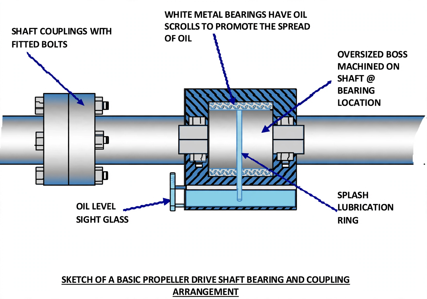
Supporting bearings are cast in two halves and are usually white metal lined, with oil scrolls cut into them to distribute splash lubrication; ball bearing supports are used but have been reported as noisy and tending to run hot.
In the after peak tank the shaft has inboard and outboard seals with nitrile rubber or viton lip seals sealing against a bronze liner shrunk-fit around the cast iron shaft.
Wear in the seals creates grooves, allowing sea water in, reducing lubrication and wearing the bronze liner; the resulting drop of the shaft due to propeller weight is the propeller drop, measured with a Pokers gauge.
1. The Shaft Line & Shaft Construction
The propeller shaft is bolted to the main engine flywheel, passing through the thrust block and then along the shaft tunnel. Here it is supported by the shaft bearings before passing through the stern tube to drive the ship's propeller.
Interactive 3D: Propeller Shaft, Bearings, Seals & Drop
Orbit the full shaft line and select any part to isolate it. Switch modes across Shaft Line, Coupling & Bolting, Bearings & Lubrication and Seals & Propeller Drop. Press Play Sequence to run the bolt-up, lubrication and wear → ingress → drop animations. Use Full Screen to view without the side panel.
Loading interactive 3D propeller shaft model…
Construction:
The shaft is manufactured from forged steel, complete with coupling flanges.
It is machined leaving a larger diameter at the location of the shaft bearings.
This bearing section has to have a fine finish in order to run within the white metal bearing.
Figure 1: Complete Marine Shaft Line Architecture. Shows the sequence from engine flywheel through the Michell thrust block, intermediate shaft supported on plummer block bearings inside the tunnel, and through the aft peak bulkhead gland into the stern tube to drive the propeller.
2. Coupling Flanges & Bolting
The shaft coupling flange faces are accurately machined.
The bolt holes are reamed to accept fitted bolts.
The flanges are bolted together using high-tension bolting, which is tightened using hydraulic tensioning gear.
Why Fitted Bolts & Hydraulic Tensioning?
Fitted (reamed) bolts fill the hole completely, so they transmit torque by shear rather than relying on friction — essential for the enormous torque of a main shaft. Hydraulic tensioning stretches the bolt precisely to a controlled load, giving a repeatable, reliable joint that does not work loose.
Figure 2: Coupling Flange Anatomy & Hydraulic Bolt Tensioning. Fitted bolts machined to micrometer tolerance fill reamed holes completely to transmit torque by shear. Hydraulic tensioners apply purely axial stretch up to 1,500 bar, ensuring uniform, twist-free clamping preload across all coupling bolts.
Photo: Shaft coupling and bearing — flange, fitted bolts and plummer block support.
3. Bearings & Lubrication
The supporting bearings are cast in two halves and are usually white metal lined.
These have oil scrolls cut into them to distribute the splash lubrication.
Nowadays ball bearing shaft supports are being used, but they have been reported as being quite noisy with a tendency to run hot.
Splash Lubrication & Oil Scrolls
Oil is picked up by a ring or splash arrangement and spread along the shaft by the oil scrolls — helical grooves machined inside the white metal bearing. These distribute oil evenly over the journal, preventing metal-to-metal contact and overheating.
Figure 3: Plummer Block White Metal Bearing & Helical Oil Scrolls. The loose splash ring lifts lubricating oil from the pedestal sump to the upper crown scraper. Machined helical oil scrolls then spread the lubricant uniformly across the journal to build a load-bearing hydrodynamic oil film.
4. Stern Tube Seals & Propeller Drop
Stern Tube Seals:
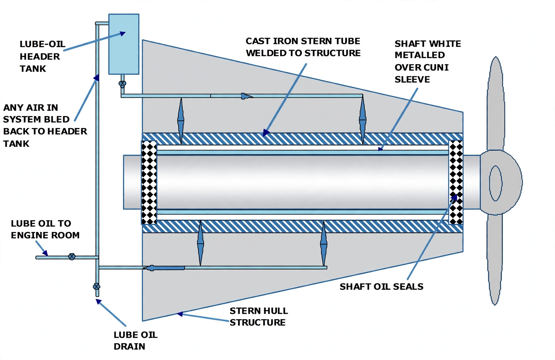
The propeller shaft in the after peak tank is provided with inboard and outboard seals.
These seals contain nitrile rubber or viton lip seals, which seal against a bronze liner shrunk-fit around the cast iron propeller shaft.
After a few years the seals create grooves on the liner and naturally lose sealing, so sea water can easily find its way inside.
This reduces the lubrication effect and creates wear of the bronze liner.
Propeller Drop:
With enough clearance, the shaft comes down by a certain amount because of the propeller weight.
This drop in the propeller shaft is termed propeller drop, and it is measured by a Pokers gauge.
Excessive propeller drop indicates worn stern tube bearings/seals and requires rectification at drydock.
Why Sealing Matters
Sea water ingress through worn lip seals destroys the lubricating oil film, accelerates wear of the bronze liner and stern bearing, and eventually allows the shaft to drop. Propeller drop is therefore a key survey measurement of stern gear condition.
Figure 4: Stern Tube Seal Grooving & Propeller Drop Measurement. Inboard and outboard lip seals protect the tailshaft bronze liner. Over time, sediment grooves the liner, inducing water ingress and accelerated bearing wear. In drydock, a calibrated Pokers gauge measures the resulting downward shaft sag ("propeller drop") against class limits.
Photo: Stern tube seals — inboard and outboard lip seals on the bronze liner.