
Back to Ship Construction & Naval Architecture
Ship Construction & Naval Architecture

Anti-Heeling System: Operation, Types & Safety

How a ship auto-detects heel and transfers ballast to stay upright, and the difference between pneumatic and pump systems.

7 min read
Intermediate
Ship Construction & Naval Architecture
Key Principles at a Glance 6 points
  • Heeling is when a ship tilts to one side (port or starboard) and does not return to its upright position; it is unsafe for the ship, its machinery and the people on board.
  • The main reasons for a ship heeling are strong winds, hard and speedy turns, and uneven cargo loading; the most common cause is uneven cargo loading and unloading.
  • The anti-heeling system automatically detects the heeling angle and compensates for it by transferring ballast water from the heeled side to the opposite side, keeping the vessel upright.
  • This allows continuous cargo loading and unloading without stopping for list correction, saving considerable time in port.
  • There are two widely used types: the pneumatic system (air forced into one tank and purged from the other to move water rapidly) and the water pump system (motor-driven reversible or non-reversible pump with remote-controlled valves).
  • Level control switches are fitted in the ballast tanks to avoid low level or over-filling and over-pressurising, and limit switches protect the system and its personnel.

1. What is Heeling & Why It Matters

When the ship tilts to one of its sides — that is, port or starboard — and does not return to its upright position, it is known as heeling of the vessel. Heeling is unsafe for the ship, its machinery, and the people on board.

The Main Reasons for a Ship Heeling:

  • Strong winds acting on the windage area of the hull and deck cargo.
  • Hard and speedy turns, which generate a centrifugal heeling moment.
  • Uneven cargo loading — and out of the three reasons, the most common cause is uneven cargo loading and unloading.
Why Heel Must Be Controlled

A persistent list reduces stability margins, stresses the hull, makes cargo operations difficult, and endangers personnel. An anti-heeling system keeps the vessel upright so that cargo work can continue safely and without interruption.

CAUSES OF SHIP HEELING & ASYMMETRIC PORT CARGO LOADS CONTAINER / RO-RO QUAY Sea Water Level Heavy 40t Containers Off-Center Load Twisted Ramp θHEEL ~4° DANGERS OF PORT HEEL: • Severe torsional twist of stern ramp • Cell guide binding & crane stop • Forklifts & trailers slide on deck • Mooring line overload & parting PRIMARY CAUSES & IMPACT OF LIST/HEEL DURING PORT OPERATIONS Uneven Cargo Operations (Primary Cause): Modern container cranes and heavy Ro-Ro cargo roll rapidly onto one side, producing abrupt transverse listing moments. Environmental & Maneuvering Forces: Strong beam winds against high container stacks or high-speed rudder maneuvers generate centrifugal/aerodynamic heeling. • Automated anti-heeling compensates in real time, eliminating crane interruptions, port delays, and linkspan ramp damage.
Figure 1: Vessel Heeling During Port Operations. Fast asymmetric cargo loading creates an immediate listing moment. Without anti-heeling compensation, severe ramp twisting, container cell guide jamming, and vehicle slippage occur, forcing crane operations to halt.

2. How the Anti-Heeling System Works

The anti-heeling system of a ship automatically detects the heeling angle and compensates for it. This allows the vessel to have continuous loading and unloading of cargo without stopping in between for list correction — saving considerable time in port.

Working Principle:

  • In this system, ballast tanks are internally connected to each other by means of pipe lines, automatic valves, and control systems.
  • When the ship heels to any of its sides, the heeling sensor sends the signal for a change of the ship's angle (with respect to its upright position) to the master control panel.
  • This change in heeling angle is compensated by auto-transferring water from the heeled side to the other side of the ship, making the vessel upright.
  • Level control switches are also installed in the ballast tanks involved with the anti-heeling system to avoid low level or over-filling, and hence over-pressurising, of the tanks.
AUTOMATIC CLOSED-LOOP ANTI-HEELING CONTROL ARCHITECTURE PORT HEELING TANK (Water Level Falling ↓) Level Sensor STBD HEELING TANK (Water Level Rising ↑) Level Sensor PUMP Valve 1 (Open) Valve 2 (Open) Rapid Ballast Transfer (→ ~1,500 m³/h) HEEL INCLINOMETER Accuracy ±0.05° MASTER PLC PANEL Deadband ±0.5° Setpoint AUTOMATIC CLOSED-LOOP COMPENSATION WORKFLOW Step 1 (Sensing): Precision electrolytic inclinometer senses heel deviation beyond preset deadband (typically ±0.3° to ±0.5°). Step 2 (Actuation): PLC starts reversible pump and opens cross-flooding butterfly valves, transferring ballast from low (heeled) to high side. Step 3 (Cutoff): When ship returns to upright threshold (within ±0.1°), pump stops and valves seal immediately, locking the stabilizing water mass.
Figure 2: Closed-Loop Anti-Heeling Architecture. An inclinometer feeds real-time heel angles to the master PLC. Once the angle exceeds the setpoint (0.3–0.5°), the bi-directional pump shifts ballast across the cross-duct to the high side until the ship is restored to upright.
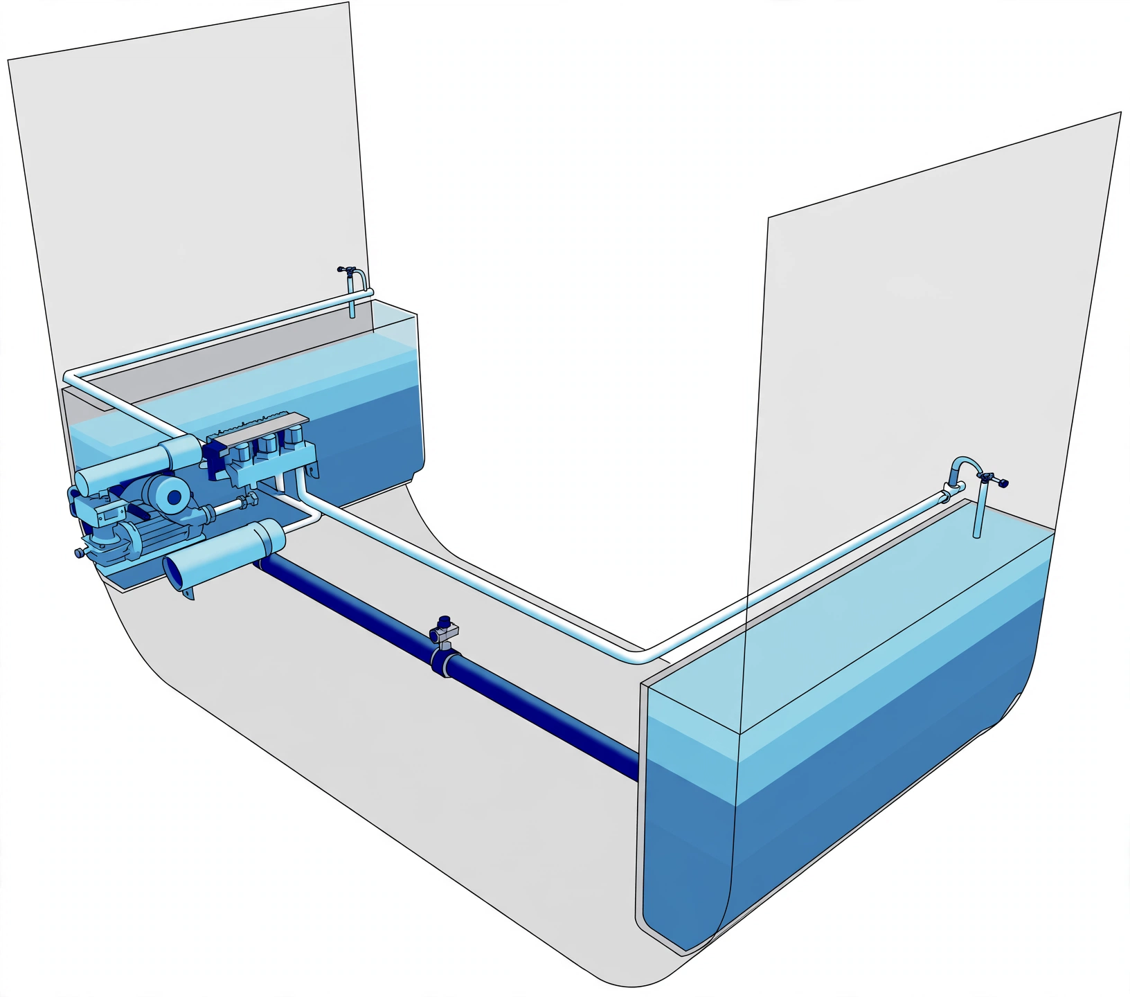
Anti-heeling tank arrangement showing port and starboard ballast tanks and transfer duct
Photo: Anti-heeling tanks — connected ballast tanks for transverse transfer.
Interactive 3D: Anti-Heeling Tanks, Pump & Pneumatic Transfer

Orbit the midship block and select any part to isolate it. Switch modes across Heel Detection, Water Pump System, Pneumatic System and Level & Safety. Use Full Screen to view the model without the side panel.

Loading interactive 3D anti-heeling model…

3. Types: Pneumatic System vs Water Pump System

There are two widely used anti-heeling systems on board ships:

1) Pneumatic System:

  • This system comprises an air purging arrangement and a regulating valve system to force air on the top of a ballast tank.
  • The air is forced on one tank and purged from the other, making the water rapidly flow from the pressurised tank to the purged tank.
  • This transfer of water is used to upright the vessel in quick time.

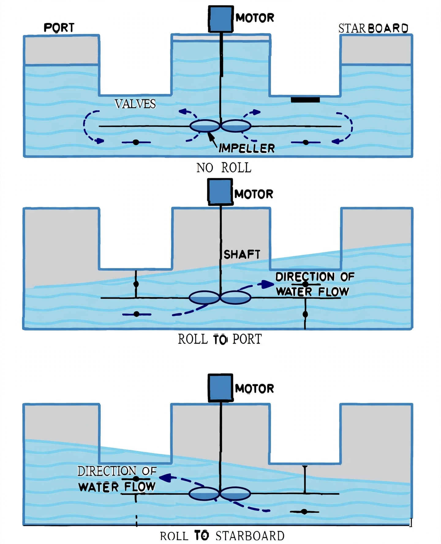
2) Water Pump System:

  • The pump system consists of an electrical motor-driven water pump, which can be a reversible or non-reversible pump.
  • It is connected with remote-controlled valves that can direct ballast water flow between the tanks.
1. PNEUMATIC AIR-PURGE SYSTEM AIR BLOWER Rotary Screw Blower Blow (+P) Vent / Purge +AIR PRESSURE ATM PURGE Passive U-Duct PNEUMATIC SYSTEM CHARACTERISTICS: No submerged pump moving parts: Water cross-duct contains no impeller; zero cavitation or seal wear. Extremely fast reaction: Air overpressure shifts up to 4,000 m³/h in seconds. Safety note: Requires structural tank reinforcement and high-integrity pressure/vacuum valves to prevent tank rupture. • Typical on large container vessels and train ferries. 2. REVERSIBLE WATER PUMP SYSTEM Open Vent Open Vent Port Wing Tank Stbd Wing Tank REV Reversible Impeller WATER PUMP SYSTEM CHARACTERISTICS: Atmospheric tanks: Ballast tanks are vented to air, avoiding high internal structural tank pressure. Reversible axial-flow pump: Instant flow reversal by reversing electric motor drive polarity. Alternative non-reversible: Uses continuous motor with 4-way crossover valve manifold to switch flow. • Compact installation; widely adopted on modern Ro-Ro and container feeder vessels.
Figure 3: Pneumatic System vs. Water Pump System. The pneumatic arrangement (left) uses high-volume air blowers to pressurize one tank while venting the opposite, forcing water through a simple duct. The pump system (right) utilizes an electric reversible axial-flow propeller pump operating between naturally vented atmospheric tanks.
Anti-heeling impeller pump system with valves for ballast transfer
Photo: Anti-heeling impeller system — pump and valve arrangement for rapid transfer.

4. Advantages & Safety of the Anti-Heeling System

Advantages:

  • Allows safer and rapid cargo loading and unloading.
  • Shortens harbour time and saves port dues.
  • Reduces damage to the ramp, rolling cargo and containers.
  • Ensures safety of the ship and personnel.

Safety of the System:

  • Level control switches prevent low level and over-filling of the anti-heeling ballast tanks, avoiding over-pressurisation.
  • Limit switches protect the system and personnel by limiting travel/operation of the valves and pumps.
  • The system is interlocked with the master control panel so that transfer only occurs when required and within safe tank limits.
ANTI-HEELING SAFETY SAFEGUARDS, LEVEL INTERLOCKS & SHUTOFF ANTI-HEELING WING TANK PV Relief Head HIGH-HIGH LEVEL (95%) → Emergency Pump Trip (Prevents Over-pressure) HIGH LEVEL STOP (90%) Normal Working Water Band (20% – 85%) LOW-LOW LEVEL (10%) → Pump Suction Cutoff (Prevents Cavitation) SAFETY INTERLOCK & PROTECTION LOGIC 1. Over-Filling & Rupture Prevention High-High float switch shuts pump in < 0.2s and seals isolating valves. 2. Dry-Run & Cavitation Interlock Low-Low float prevents suction unseating and air ingress into impeller. 3. Valve Limit Switch End-Position Verification Pump motor start circuit interlocked: will NOT start unless valves are 100% open. 4. Manual Emergency Override & Audio Alarm Bridge / Cargo Control Room (CCR) instant E-Stop and manual override. CLASSIFICATION SURVEY & SAFETY INTERLOCK RULES Mandatory Redundant Sensors: Dual independent level transmitters (ultrasonic continuous + magnetic float switches) protect each wing tank. Anti-Overpressurisation: High-capacity pressure/vacuum air breather heads relieve excessive compressed air heads in pneumatic systems. • Safety Limit Switches on hydraulic actuators guarantee positive valve seating, preventing unintended ballast drain between tanks at sea.
Figure 4: Anti-Heeling Safety Safeguards & Interlocks. High-High level switches prevent tank overpressurization, while Low-Low sensors prevent pump cavitation. Limit switches verify valve positions before the pump can energize, backed by emergency bridge trip alarms.
Surveyor Asks

Surveyors commonly ask: "What are the causes of heeling and how does the anti-heeling system correct it?" Answer with the three causes, the sensor → control panel → automatic valve/pump → water transfer chain, and remember to mention level control switches and the two system types.