Demystifying transverse stability, the righting lever (GZ), and why stiff ships snap while tender ships linger.
7 min read
Intermediate
Ship Construction & Naval Architecture
Key Principles at a Glance7 points
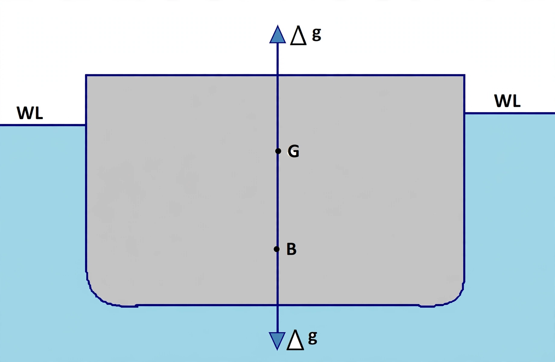
Equilibrium at sea requires two equal and opposite forces: Gravity acting downward through G, and Buoyant upthrust acting upward through B.
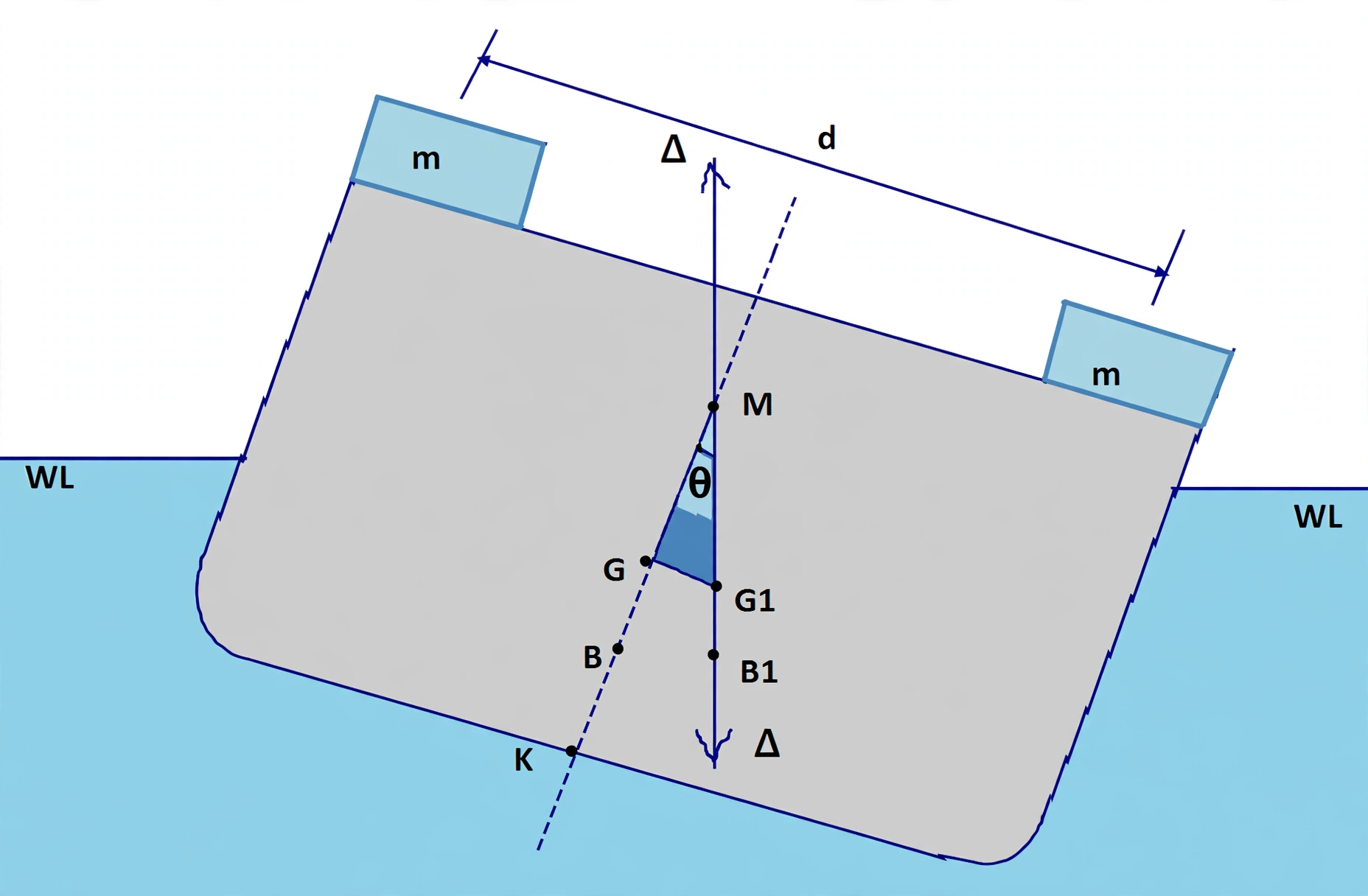
When inclined to angle θ, underwater volume shifts to the low side, moving the Center of Buoyancy from B to B₁.
The vertical through B₁ cuts the centerline at the Transverse Metacenter (M). Metacentric Height GM = KM - KG.
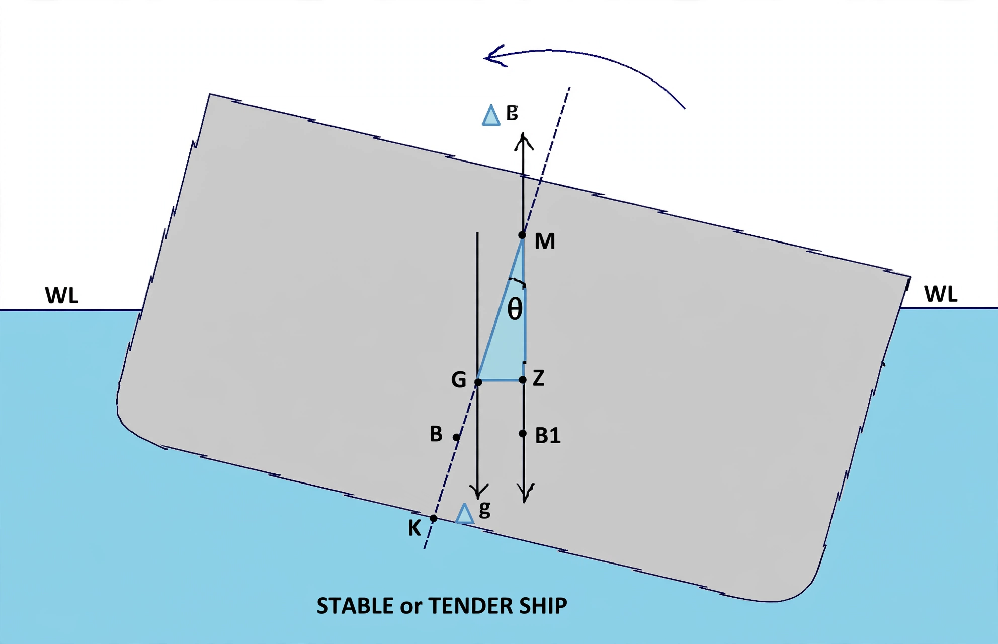
Dropping a perpendicular from G to the buoyancy line forms the right-angled triangle ΔGZM, establishing GZ = GM · sin(θ).
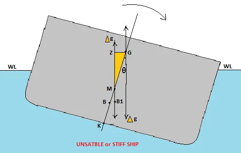
A "Stiff Ship" has a large GM, causing violent snap rolls that fatigue steel and cargo lashings.
A "Tender Ship" has a small GM, causing sluggish, slow roll periods that feel comfortable but leave little reserve against capsize.
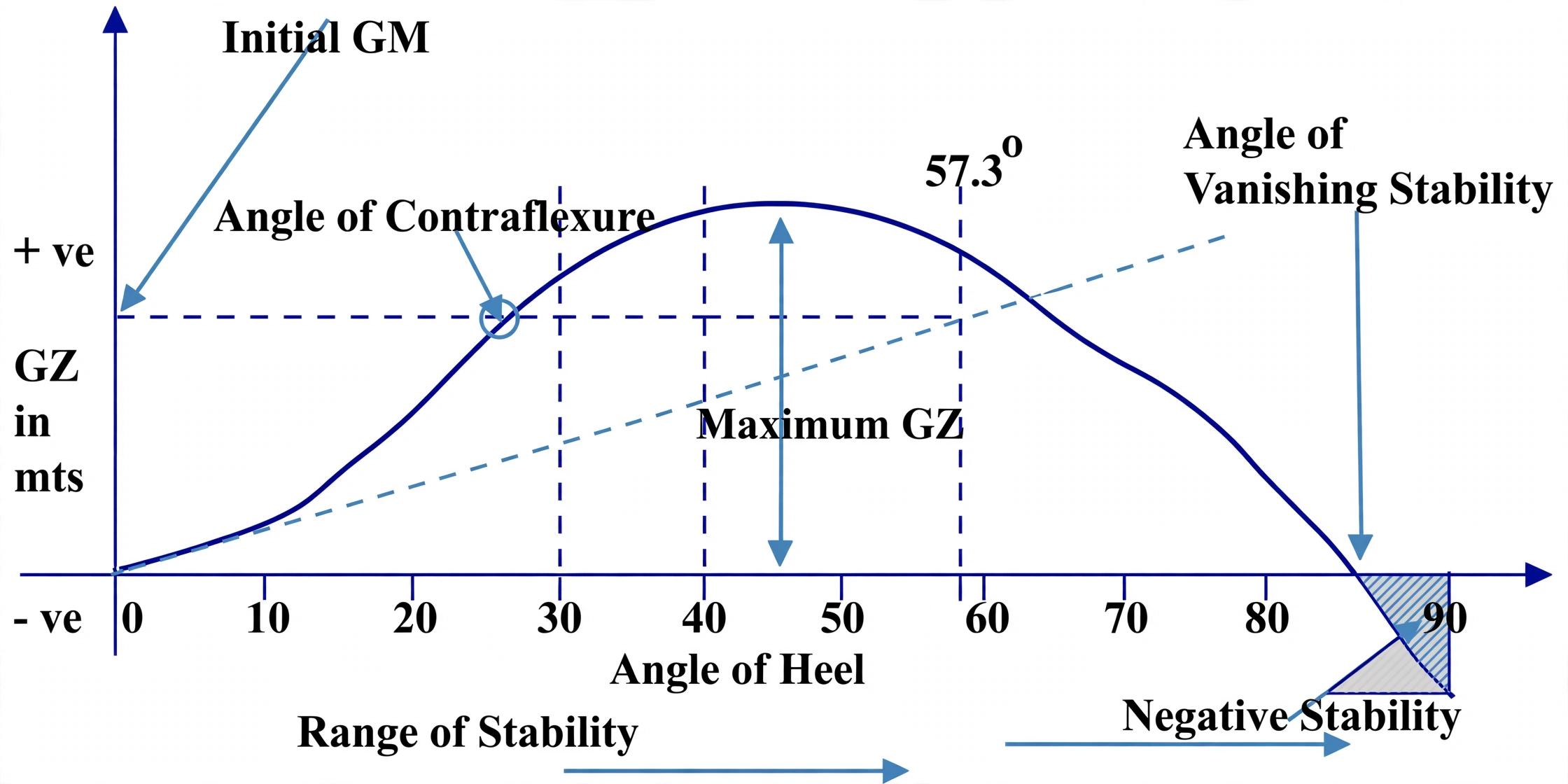
The Curve of Statical Stability (GZ Curve) plots GZ across all angles up to the Angle of Vanishing Stability.
1. The Upright Equilibrium: Gravity vs. Buoyancy
A ship floats on the ocean through the delicate balance of two monumental, equal and opposite forces:
Force of Gravity (Displacement Δ)
Acts vertically downward through the vessel's Center of Gravity (G). Point G is the geometric centroid of all onboard weights (hull steel, cargo, fuel, ballast, crew, and machinery). Its vertical height above the keel is KG.
Force of Buoyancy (Upthrust Δ)
Acts vertically upward through the Center of Buoyancy (B). Point B is the geometric center of the underwater displaced volume of water. Its height above the keel is KB.
In calm water with no external wind or wave forces, both forces lie on the exact same vertical centerline (CL). The ship is in static equilibrium.
Figure 1: Upright Static Equilibrium. Gravity acts downward through the Center of Gravity (G), and equal buoyant upthrust acts upward through the Center of Buoyancy (B). Because both lie along the exact same vertical centerline, the vessel is in equilibrium with zero heeling or restoring moment.
Photo: Upright equilibrium — gravity through G aligned with buoyancy through B on the centerline.
2. The Stability Triad: G, B, M & The Righting Lever GZ
When external wind or waves heel the ship to an angle θ, the underwater hull shape transforms:
An emerged wedge of volume leaves the water on the high side, while an immersed wedge enters the water on the low side.
Because underwater volume shifts toward the low side, the Center of Buoyancy shifts outwards from B to B1.
The vertical line of buoyant upthrust through B1 cuts the original ship centerline at the Transverse Metacenter (M).
From G, dropping a perpendicular onto the vertical buoyancy line through B1 produces point Z. The horizontal distance GZ is the Righting Lever.
Figure 2: The Righting Lever GZ & The Stability Triad. When heeled to angle θ, underwater volume shifts to the low side, moving the Center of Buoyancy from B to B₁. Dropping a perpendicular from G to the vertical line of buoyant upthrust forms the right-angled triangle ΔGZM at point Z, proving mathematically that GZ = GM · sin(θ).
Photo: Heel geometry — B shifts to B1, forming triangle GZM and righting lever GZ.
The Right-Angled Triangle ΔGZM Proof
In the technical diagram above, examine the right-angled triangle formed by points G, Z, and M:
The angle at point Z is a true right angle: ∠GZM = 90°.
The angle at the Metacenter M is equal to the vessel's heel angle: ∠GMZ = θ.
The restoring couple that pulls the vessel back upright is the Righting Moment:
Righting Moment = Δ × GZ = Δ × GM × sin(θ)
3. The Curve of Statical Stability (GZ Curve)
While the formula GZ = GM · sin(θ) is accurate for small inclinations up to 10°–15°, as heel angle increases beyond 15°, the deck edge immerses and the underwater waterplane shape changes dramatically. Naval architects therefore plot the GZ Curve across all angles from 0° to 60°+.
Figure 3: The Curve of Statical Stability (GZ Curve). Key landmarks illustrated: (1) Initial slope at 0° intersecting 57.3° (1 radian) at a height equal to initial GM, (2) Point of Contraflexure where deck edge submerges, (3) Maximum GZ peak lever (IMO: ≥ 0.20m at ≥ 30°), and (4) Angle of Vanishing Stability where positive righting levers cease.
Photo: GZ curve — maximum lever, contraflexure and vanishing angle landmarks.
Photo: Cross curves — KN values across displacement for constructing GZ curves.
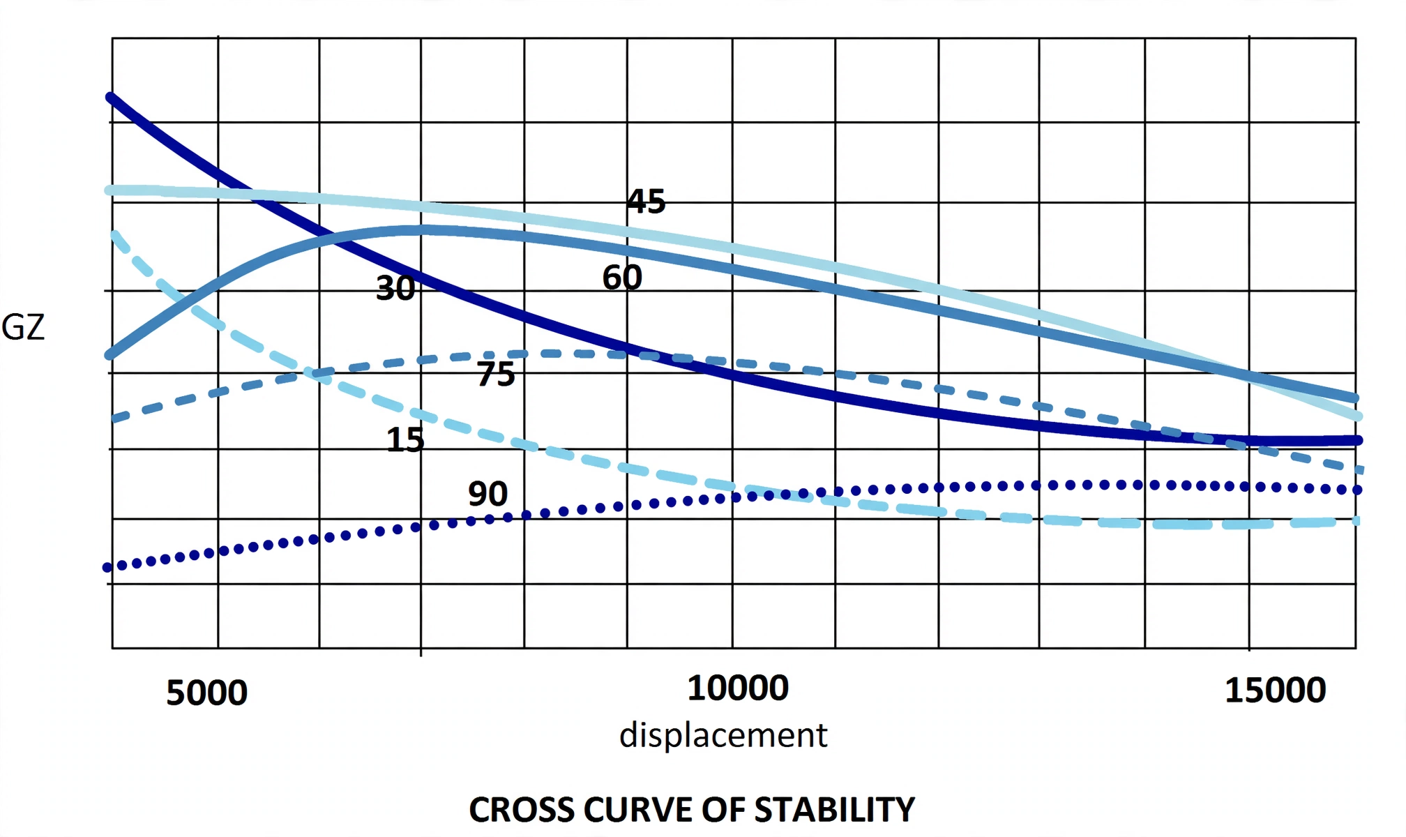
Cross Curves — Where the GZ Curve Comes From (Q35):
GZ cross curves: plotted for an assumed KG — read the righting lever for any heel at any displacement straight off the curves; if the ship's actual KG differs, apply a KG correction to every lever taken.
KN cross curves: the same family built for an assumed KG of zero — KN is the righting lever measured from the keel, not from G.
Use: cross curves supply the GZ-at-every-heel values from which the voyage static-stability curve (one KG, one displacement) is drawn.
Static-Stability Criteria Drill — Seven Numbers:
Initial GM ≥ 0.15 m.GZ ≥ 0.20 m at 30° heel.Max GZ at heel > 30° (never less than 25°).
Area under GZ: ≥ 0.055 m·rad to 30°; ≥ 0.09 m·rad to 40°; ≥ 0.03 m·rad between 30° and 40° (or 30° to angle of downflooding — the angle at which deck immersion takes place).
Righting moment at any heel = GZ × displacement.Dynamic stability (work done heeling to that heel) = displacement × area under GZ to that heel.
Key Landmark Points on the GZ Curve:
1
Initial Slope: The tangent to the curve at 0° intersects the 1-radian (57.3°) vertical ordinate at a height exactly equal to the initial GM.
2
Point of Contraflexure: The inflection point where deck edge immersion begins. Beyond this angle, the rate of increase of GZ slows down.
3
Maximum GZ (Peak Lever): IMO Code on Intact Stability mandates that maximum GZ must occur at an angle of heel ≥ 30° (and never less than 25°), with GZ ≥ 0.20 m at 30°.
4
Angle of Vanishing Stability: The angle where GZ falls back to zero. Beyond this inclination, the righting arm inverts into an upsetting moment, resulting in capsize.
4. Stiff vs. Tender Ships: Seafarer's Operating Balance
A vessel's metacentric height dictates its rolling behavior in seaways. More GM is not always better:
Operating Trait
Stiff Ship
Tender Ship
Metacentric Height (GM)
Very Large (excessive low ballast or heavy bottom cargo)
Very Small (top-heavy cargo or high deck loads)
Righting Arm (GZ)
Enormous, powerful righting lever
Sluggish, small righting lever
Rolling Period (T)
Short, violent snap rolls (4–8 seconds)
Long, gentle, sluggish roll periods (18–25+ seconds)
Deceptively comfortable for crew, but dangerously small margin against capsize
Figure 4: Stiff vs. Tender Ships. A "Stiff Ship" (left) has a low Center of Gravity and excessive GM, producing powerful righting levers that cause violent snap rolls. A "Tender Ship" (right) has a high Center of Gravity and tiny GM, producing sluggish, slow rolls with dangerously narrow margins against capsize.
Photo: Heeled GZ illustration A — righting lever development at angle of heel.
Photo: Heeled GZ illustration B — righting lever development at larger heel.
5. The Inclining Experiment: Measuring GM & KG
The inclining experiment is a simple experiment carried out on the completed ship to determine the metacentric height, and hence the height of the centre of gravity (KG) of the ship.
Why It Is Carried Out:
If the height of the centre of gravity of the empty ship is known, it is possible to calculate its position for any given condition of loading.
It is therefore necessary to carry out the inclining experiment on the empty ship (or as near to empty as possible).
The experiment is commenced with the ship upright.
Theory & Calculation:
A small mass m is moved across the ship through a distance d. This causes the centre of gravity to move from its original position G on the centreline to G1.
If Δ = displacement of the ship, then: GG1 = (m × d) / Δ
The ship heels to an angle θ; the centre of buoyancy moves from B to B1, in the same vertical line as G1. The vertical through B1 intersects the centreline at M, the transverse metacentre.
Since GG1 = GM tan θ, we get GM = (m × d) / (Δ tan θ).
To determine the angle of heel, a pendulum is suspended from, say, the underside of a hatch. If the deflection is a and the pendulum length is L, then tan θ = a / L, so GM = (m × d × L) / (Δ × a).
The height of the transverse metacentre above the keel (KM) is found from the metacentric diagram, hence KG = KM − GM.
How the Experiment Is Conducted On Board:
Use a stabilograph to record the curve; the experiment must be carried out very carefully to ensure accurate results.
At least two pendulums are used, one forward and one aft, made as long as possible and suspended from a convenient point such as the underside of a hatch.
A stool is arranged in way of each pendulum on which the deflections are recorded, and the pendulum bobs are immersed in water or light oil to dampen the swing.
Four masses A, B, C and D are placed on deck, two each side of the ship near midships, their centres as far as possible from the centreline.
The mooring ropes are slackened and the ship-to-shore gangway removed. The draughts and density of water are read as accurately as possible.
The inclining masses are then moved, one at a time, across the ship until all four are on one side, then all four on the other side, and finally two on each side.
The deflections of the pendulums are recorded for each movement, and an average is used to determine the metacentric height.
The experiment should be carried out in calm weather.
Figure 5: The Inclining Experiment. A known mass m is shifted a distance d, heeling the ship by θ. Pendulums measure tan θ = a/L, giving GM = (m·d·L)/(Δ·a); KM from the metacentric diagram then gives KG = KM − GM.