How flat plate, bar, and duct keels form the backbone of modern vessels, and why bilge keels use sacrificial ground bars for roll damping.
7 min read
Intermediate
Ship Construction & Naval Architecture
Key Principles at a Glance7 points
The keel is the principal centerline longitudinal structural member, serving as the foundational backbone of the vessel from stem to stern.
Modern ocean-going vessels utilize a Flat Plate Keel, featuring a thick bottom strake (1–2m wide) welded to the central longitudinal girder and flanked by garboard strakes.
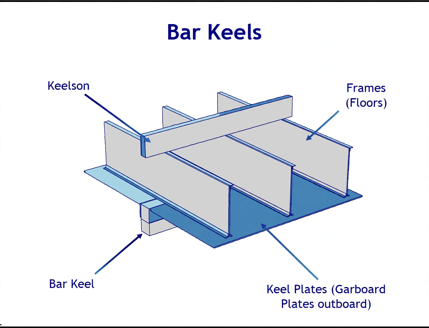
A Bar Keel features an external solid steel bar projecting below the hull, used primarily on tugs and ferries operating in shallow waters where grounding resistance is vital.
A Duct Keel (Box Keel) forms a watertight centerline pipe tunnel in the double bottom forward of the machinery space, carrying ballast and fuel pipes isolated from cargo holds.
Duct keels feature two longitudinal side girders spaced no more than 1.83 meters apart so they can sit securely on standard drydock blocks.
Bilge keels run along the midship turn of the bilge (approx. 1/2 ship length) to dampen roll motions by penetrating the boundary layer of water.
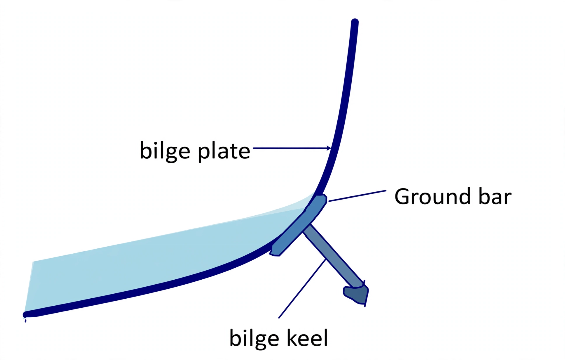
CRITICAL SAFETY PRINCIPLE: Bilge keels are NEVER welded directly to the shell. They are welded to a sacrificial ground bar so groundings tear the fin off without breaching the watertight hull envelope.
1. The Backbone of the Ship: Flat Plate Keel vs. Bar Keel
In naval architecture, the keel is the primary longitudinal strength member along the bottom centerline. It resists global longitudinal bending (hogging and sagging) and supports the entire weight of the vessel when resting on drydock blocks.
Flat Plate Keel (Modern Sea-Going Ships)
Formed by a heavy flat steel plate strake (1.0 to 2.0 m wide) forming the bottom centerline. Maintains full scantling thickness for 3/5th of ship length amidships, securely welded to the vertical center girder and flanked on both sides by garboard strakes.
Bar Keel (Specialized / Grounding Craft)
A solid forged steel bar projecting below the bottom shell, supported internally by a vertical keelson. Primarily found on tugboats, ferries, and rivercraft operating in shallow waters where grounding and bottom scouring are frequent.
Interactive 3D: Keel, Duct Keel & Bilge Keel Model
Orbit the midship section, select any component to isolate it, then switch modes to inspect the Flat Plate Keel, Bar Keel, Duct Keel, Bilge Keel and the sacrificial Ground Bar.
Loading interactive 3D keel model…
Figure 1: Structural Comparison of Keel Architectures. Modern commercial ships use a Flat Plate Keel (left), a heavy centerline strake (1–2 m wide) welded to the vertical center girder and supported directly by drydock keel blocks. Small craft, tugs, and river vessels use a Bar Keel (right), featuring a solid forged bar projecting below the hull envelope to absorb severe bottom scouring and grounding shocks.
Photo: Bar keel — solid forged bar projecting below the bottom shell for grounding resistance on tugs and shallow-water craft.
2. The Duct Keel (Box Keel): Internal Watertight Pipe Tunnel
A Duct Keel (often called a Box Keel) is an internal watertight tunnel built along the vessel's centerline within the double bottom, extending from the collision bulkhead aft to the forward machinery space bulkhead.
Its primary purpose is to provide a protected, accessible passageway for ballast, bilge, and fuel transfer pipework, isolating pipes from direct cargo contact and preventing cargo contamination in the event of pipe rupture.
Why is a Duct Keel NOT fitted in the Engine Room?
A duct keel is never required within the machinery space or further aft. Inside the engine room, pipework runs safely along the top of the double bottom tank top. Aft of the engine room, lines pass cleanly through the Shaft Tunnel.
Figure 2: Duct Keel (Box Keel) Transverse Anatomy. Extends forward of the engine room to the collision bulkhead, forming a protected centerline pipe tunnel. The two watertight side girders must be spaced no more than 1.83 m (6 ft) apart so that both girders bear securely upon standard shipyard drydock blocks during docking.
3. Bilge Keels: Hydrodynamic Roll Damping & Boundary Layer
Fitted at the turn of the bilge along approximately one-half of the ship's length amidships, the Bilge Keel is the simplest and most reliable passive stabilization device in commercial shipping.
As the ship rolls, the bilge keel projects into the sea and creates high-resistance hydrodynamic turbulence (vortex shedding), transforming rolling kinetic energy into localized eddy dissipation.
Figure 3: Hydrodynamic Roll Damping Principle of the Bilge Keel. As the vessel rolls in sea waves, the bilge keel projects beyond the boundary layer of laminar water to shed powerful turbulent eddies (vortex shedding). The resulting hydrodynamic drag creates a counter-moment that rapidly attenuates roll amplitudes.
Photo: Bilge keel section at the turn of the bilge, projecting beyond the boundary layer to damp rolling by vortex shedding.
4. The Sacrificial Ground Bar: Shell Plating Protection
A fundamental rule in ship construction: A bilge keel is NEVER welded directly to the outer bilge shell plating!
If an obstruction (floating container, seabed reef, or tugboat) strikes the bilge keel, direct welding would tear a hole in the hull plating, flooding the double bottom or cargo holds.
Figure 4: The Sacrificial Ground Bar (Doubling Flat Bar) Connection. The bilge keel is NEVER welded directly to the hull envelope. Instead, a continuous sacrificial ground bar is welded with full-penetration welds to the outer shell, and the bilge keel fin is attached to the ground bar with lighter welds. Severe impacts will cleanly shear the fin off without breaching the vessel's watertight shell.
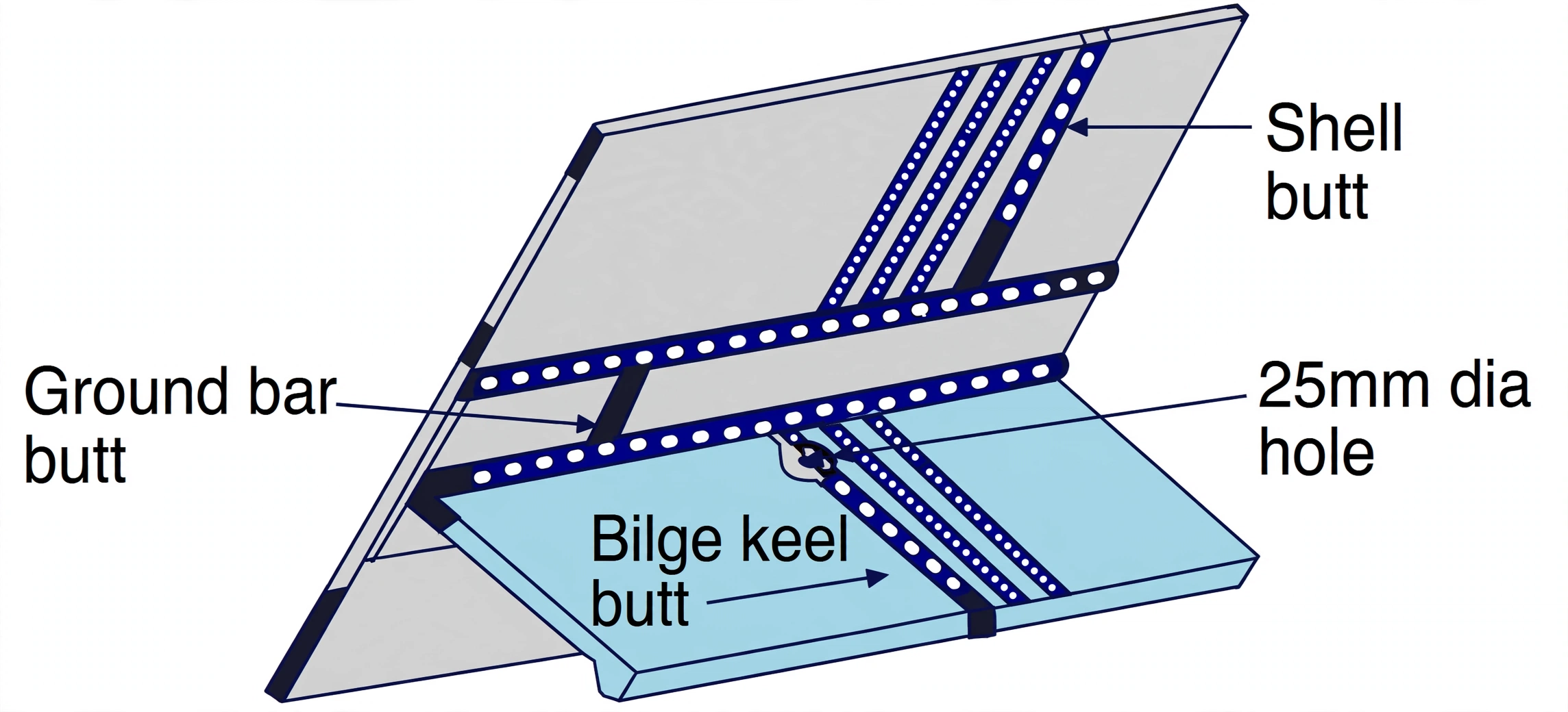
Photo: Bilge keel butt and ground-bar connection — fin welded to the sacrificial flat bar, never directly to the shell, so impacts shear the fin without breaching the hull.