
Methods of Reducing Rolling: Fin, Bilge & Tank Stabilisers
How active fins, bilge keels, and passive/active tank stabilisers fight synchronous roll and why tank water must be tuned to GM.
Key Principles at a Glance 6 points
- Fin stabilisers work like aircraft wings: aerofoil-section fins at bilge level rotate in opposite directions to generate a lift force that creates a moment opposing the roll.
- The main fin moves up to about 20° while its articulated tail flap moves a further 10°–30°, and the fins are driven by an electric motor and variable-delivery pump feeding oil to the fin tilting gear.
- Typically two fins extend from the ship side near bilge level; turning a fin down produces an upward water force and turning it up produces a downward force. Most fins are retractable (sliding fin boxes or hinged inward) for shallow-water and berthing protection.
- Bilge keels are passive roll-damping projections fitted at the bilge above the bottom shell and within the ship breadth; they must be deep enough to penetrate the boundary layer yet not so deep that rolling water force damages them.
- Bilge keels of 250 mm to 400 mm depth extend about one half of the ship length amidships and are gradually tapered at the ends.
- Free-surface tank stabilisers do not depend on the ship forward motion (suited to drill ships), but introduce a free surface that reduces stability; the tank water must be tuned to the ship GM and roll period or it can synchronise and worsen rolling.
1. Fin Stabilisers (Active Roll Damping)
Fin stabilisers are the most powerful active anti-rolling device. They work very much like an aircraft wing, providing lift — positive or negative — depending upon their aspect relative to the water flow.
Construction & Geometry:
- Aerofoil cross-section: The fins are of aerofoil section and are provided with tail flaps which can be moved relative to the main fin. This movement is accomplished automatically as the main fin rotates.
- Angles of movement: Main fins usually have a maximum movement of about 20° up or down, whilst the tail flap can move a further 10° to 30° relative to the main fin.
- Location: Two fins extend from the ship side at about bilge level, one port and one starboard.
- Opposite rotation: The fins are turned in opposite directions as the ship rolls.
How the Stabilising Moment is Generated:
The forward motion of the ship creates a force on each fin, and hence produces a moment opposing the roll:
- When the fin is turned down, the water exerts an upward force.
- When the fin is turned up, the water exerts a downward force.
Driving Machinery & Retraction:
- The fins are turned by an electric motor driving a variable-delivery pump, delivering oil under pressure to the fin tilting gear.
- The oil actuates rams coupled through a lever to the fin shaft.
- Most fins are retractable, either sliding into fin boxes transversely or hinged into the ship. Hinged fins are used when there is a restriction on the width of ship which may be allocated, such as in a container ship.
Orbit the midship section, pick any part to isolate it, then switch modes to run the active fin stabilisers, the passive bilge keels and the three free-surface tank systems — passive, controlled passive and active controlled — and watch the water lag or be driven against the roll.
2. Bilge Keels (Passive Roll Damping)
When ships were first built of iron instead of wood, a bar keel was fitted, one of its advantages being that it acted as an anti-rolling device. With the fitting of the flat plate keel the anti-rolling properties were lost. An alternative method was supplied in the form of bilge keels, which are now used in the majority of ships.
Arrangement:
- These projections are arranged at the bilge to lie above the line of the bottom shell and within the breadth of the ship, thus being partially protected against damage.
- They extend for about one half of the length of the ship amidships and are tapered gradually at the ends.
Depth — The Two Governing Factors:
The depth of the bilge keels depends to some extent on the size of the ship, but there are two main factors to be considered:
- Boundary layer penetration: The web must be deep enough to penetrate the boundary layer of water travelling with the ship. If it is too shallow, it sits in still, entrained water and develops little damping force.
- Damage risk when rolling: If the web is too deep, the force of water when rolling may cause damage to the keel or its connection to the shell.
Bilge keels 250 mm to 400 mm in depth are fitted to oceangoing ships.
3. Passive & Controlled Passive Tank Stabilizers
Three basic systems of roll-damping use free-surface tanks:
- Passive Tanks
- Controlled Passive Tanks
- Active Controlled Tanks
These systems do not depend upon the forward movement of the ship and are therefore suitable for vessels such as drill ships. However, in introducing a free surface to the ship there is a reduction in stability (loss of GM) which must be considered when loading the ship.
(a) Passive Tanks:
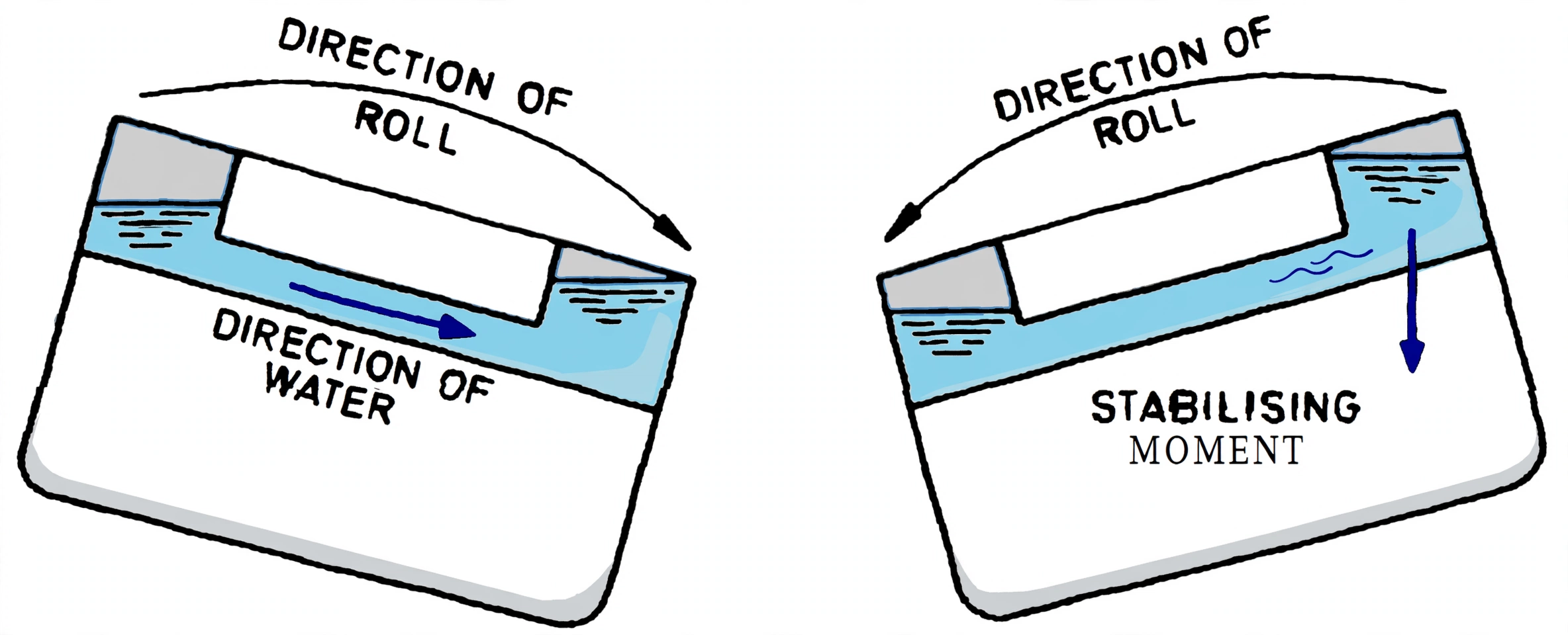
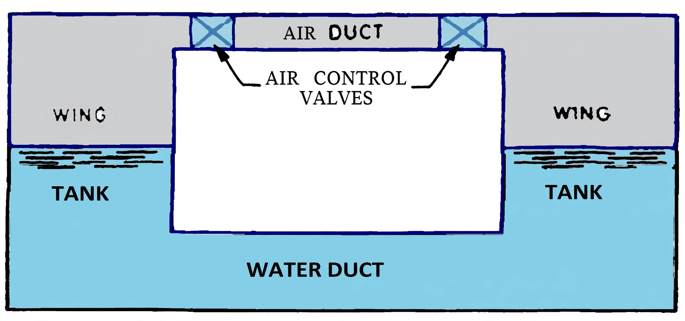
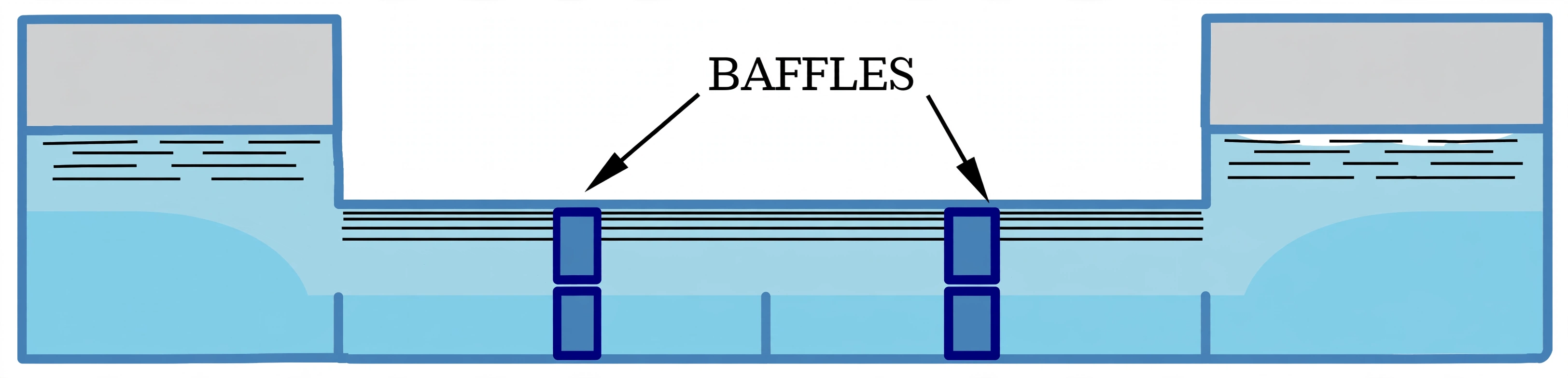
- Two wing tanks are connected by a duct having a system of baffles.
- The tanks are partly filled with water.
- When the ship rolls, the water moves across the system in the direction of the roll. As the ship reaches its maximum angle and commences to return, the water, slowed by the baffles, continues to move in the same direction.
- Thus a moment is created, reducing the momentum of the ship and hence the angle of the subsequent roll.
- Tuning is critical: The depth of water in the tanks is critical and, for any given ship, depends upon the metacentric height. The tank must be tuned for any loaded condition by adjusting the level, otherwise the movement of the water may synchronise with the roll of the ship and create dangerous rolling conditions.
- Alternatively the cross-sectional area of the duct may be adjusted by means of a gate valve.
(b) Controlled Passive Tanks:
- The principle of action is the same as for the passive system, but the transverse movement of the water is controlled by valves operated by a control system similar to that used in the fin stabiliser.
- The valves may be used to restrict the flow of water in a U-tube system, or the flow of air in a fully-enclosed system.
- The mass of water required in the system is about 2% to 2.5% of the displacement of the ship.
- With the valves closed the system is put out of action — a useful fail-safe feature.
4. Active Controlled Tanks & Roll Period Tuning
In the active controlled tank system the water is positively driven across the ship in opposition to the roll. Because the direction of roll, and hence the required direction of the water, changes rapidly, a different arrangement is needed:
- It is necessary to use a uni-directional impeller in conjunction with a series of valves.
- The impeller runs continually and the direction of the water is controlled by valves which are activated by the control system.
Design & Phase Relationship:
Careful design of the tank in terms of its shape, water capacity, and vertical positioning in the ship allows control to be exercised with respect to rolling. With correct design of tank:
- The water oscillating period will equal the roll period of the ship.
- Its motion will lag behind that of the ship by one quarter of the roll period.
- It will lag behind the wave by half of the roll period.
Water in the tank thus opposes the wave action producing the roll. Water movement between the tanks is regulated to some extent by the air valves. With the valves closed, the system is put out of action. Under this arrangement — known as the controlled passive system — the mass of water is about 2% to 2.5% of the ship's displacement.
If the tank water period does not match the ship's natural roll period, the water can move in phase with the ship and amplify the roll instead of damping it. This is why passive tanks must be tuned (by adjusting water level or duct gate valve) for every loaded condition, since the roll period changes with GM as the ship is loaded.