
Cruiser & Transom Sterns, Cant Frames & Frame Spacing
How the stern overhang is stiffened, and the frame spacing rules a surveyor expects: 1 m, 760 mm and 610 mm.
Key Principles at a Glance 5 points
- In the main body of the ship, frame spacing may not exceed 1 m between the collision bulkhead and a point one-fifth of the ship's length aft of the stem.
- In the peak tank the frame spacing must not exceed 760 mm, and in cruiser sterns it must not exceed 610 mm.
- A cant frame is one set at an angle to the centreline; such frames are fitted 610 mm apart, dividing the perimeter of the cruiser stern into small panels, and are bracketed at the top to cant beams.
- The cruiser stern overhang may be subjected to large slamming forces, so it needs substantial construction: solid floors at every frame space, a heavy centreline girder right aft at the shell and decks, cant frames/webs with short cant beams, and horizontal stringers.
- Cant frames are not required with a transom stern, because the flat stern plating can be stiffened with vertical stiffeners, with deep floors and a centreline girder at the lower region.
1. Frame Spacing Rules
Idea in one line: frames close up where the sea hits hardest — 1 m amidships, 760 mm in peak tanks, 610 mm round the cruiser stern.
Orbit the stern, select any part to isolate it, then switch modes across Frame Spacing, Cruiser Stern, Transom Stern and the Slamming load. Use Full Screen to view the model without the side panel.
Frame spacing is the fore-and-aft distance between adjacent transverse frames. Classification rules limit it depending on location, because closer framing is needed where loads are highest and hull form is most curved:
- In the main body of the ship: Frame spacing may not exceed 1 metre between the collision bulkhead and a point one-fifth of the ship's length aft of the stem.
- In the peak tank: It must not exceed 760 mm.
- In cruiser sterns: It must not exceed 610 mm.
- Cant frames are fitted 610 mm apart.
The fore end and stern experience slamming, panting and rapid changes in hull form. Closer frame spacing (smaller panels) gives greater local stiffness and resistance to these concentrated loads.
State the three frame-spacing numbers?
1 m in the main body between collision bulkhead and 0.2L aft of stem; 760 mm in peak tanks; 610 mm in cruiser sterns and between cant frames.
Why closer at the ends?
Slamming, panting and tight curvature concentrate load on small panels — closer frames keep plate spans short and stiff.
2. Cruiser Stern Construction & Cant Frames
Idea in one line: cant frames fan round the curved stern like ribs round a heel, each tied at the top to a cant beam and at the foot to a solid floor.
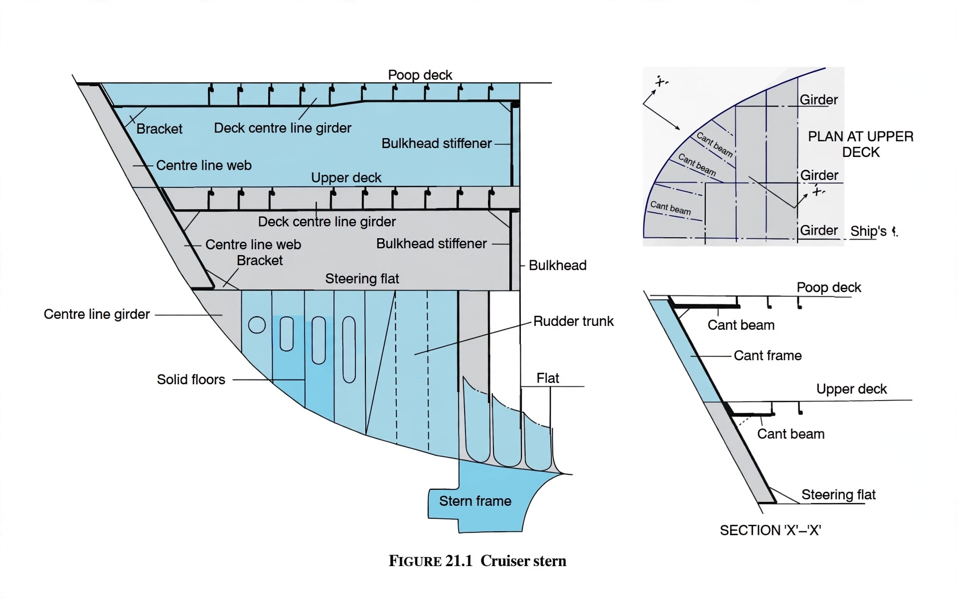
As the cruiser stern overhang may be subjected to large slamming forces, a substantial construction with adequate stiffening is required:
- Solid floors are fitted at every frame space.
- A heavy centreline girder is fitted right aft at the shell and decks.
- The stern plating is stiffened by cant frames or webs with short cant beams supporting the decks and led to the adjacent heavy transverse deck beam.
- Further stiffening of the plating is provided — or adopted in lieu of cant frames — by horizontal stringers extending to the first transverse frame.
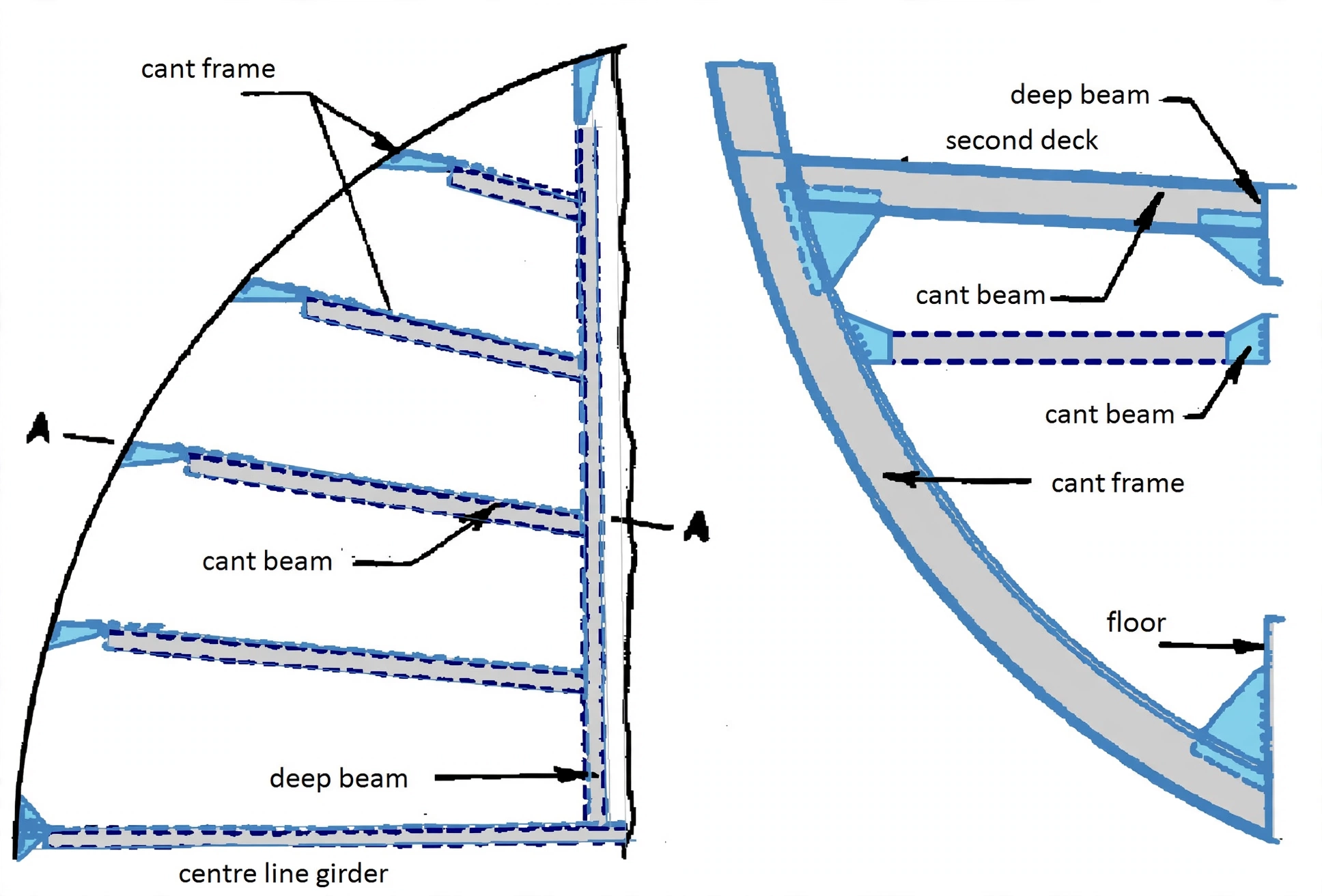
Cant Frame & Cant Beam:
- A cant frame is a frame set at an angle to the centreline of the ship.
- Such frames are fitted 610 mm apart, thus dividing the perimeter of the cruiser stern into small panels.
- At the top, these frames are bracketed to cant beams, which also lie at an angle to the centreline.
- The forward ends of the cant beams are connected to a deep beam extending right across the ship.
- At the lower ends, the cant frames are connected to a solid floor.
Foot — solid floor. Each cant frame steps onto a solid floor fitted at every frame space; the floor carries slamming load down into the double bottom.
Web — cant frame. Set at an angle to the centreline, 610 mm apart round the stern perimeter so the curved shell is divided into small stiff panels.
Head — cant beam. Bracketed to a cant beam also angled to the centreline; forward ends land on a deep transverse beam right across the ship.
Horizontal stringers run to the first transverse frame can stiffen the stern plating in lieu of cant frames — same small-panel logic, laid flat instead of fanned.
3. Transom Stern Construction
Idea in one line: a flat transom needs no angled framing — straight vertical stiffeners on a flat panel do the same job for less cost.
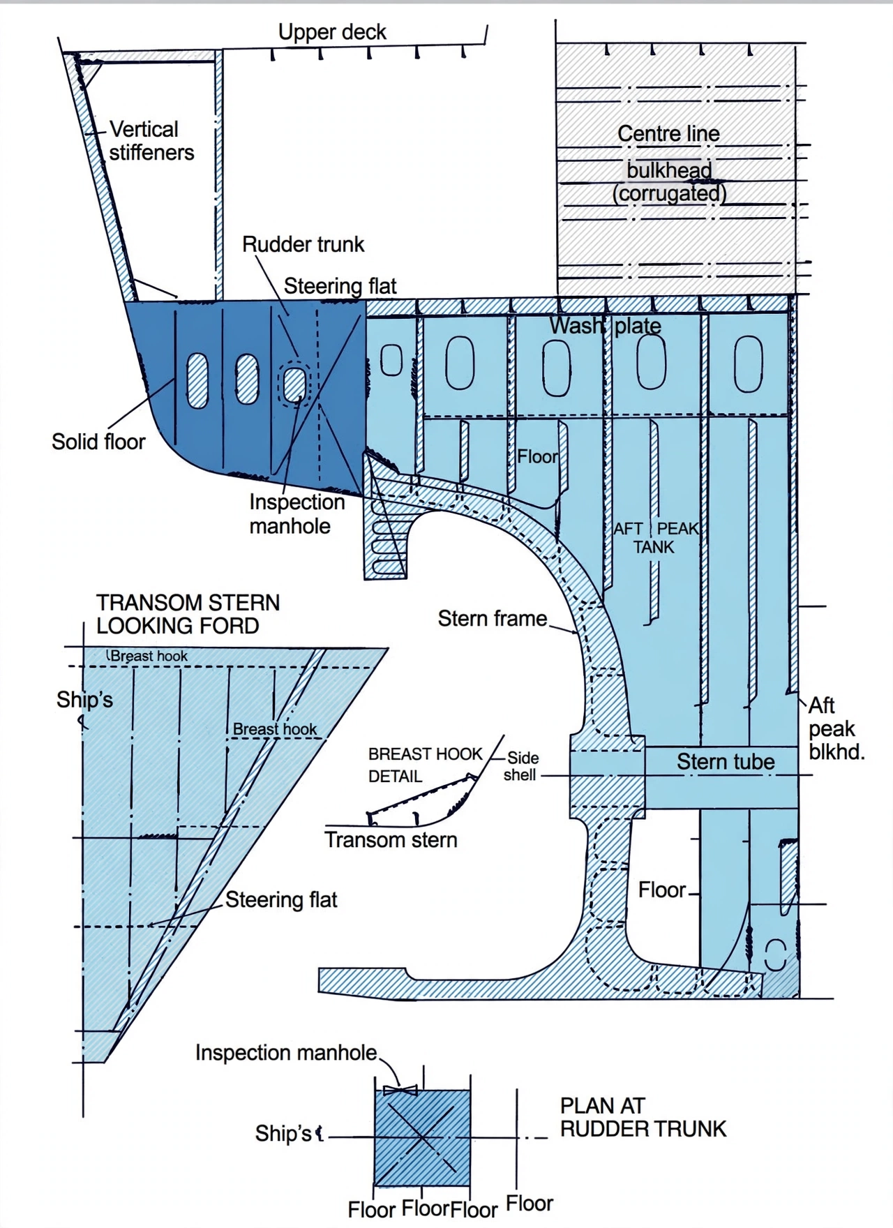
- Cant frames are not required where the transom stern is adopted, as the flat stern plating may be stiffened with vertical stiffeners.
- Deep floors and a centreline girder are provided at the lower region of the transom stern construction.
- The flat transom panel is simpler to build than the curved cruiser stern overhang and offers useful deck space and a clean wake.
A cant frame exists to stiffen a curved surface. The transom stern is a flat, vertical (or near-vertical) panel, so straight vertical stiffeners are more effective and simpler — no angled cant frames or cant beams are needed.
4. Cruiser vs. Transom Stern: Comparison
Idea in one line: curved cruiser stern buys low-speed grace at high build cost; flat transom buys deck space, cheap welding and a clean fast wake.
| Feature | Cruiser Stern | Transom Stern |
|---|---|---|
| Form | Curved overhang aft | Flat, near-vertical panel |
| Main stiffening | Cant frames/webs + cant beams | Vertical stiffeners |
| Cant frames required? | Yes | No |
| Frame spacing limit | ≤ 610 mm | — |
| Floors | Solid floors at every frame space | Deep floors at lower region |
| Centreline girder | Heavy, right aft at shell and decks | At lower region |
| Key concern | Slamming on the overhang | Simple flat panel, useful deck space |
Summary of the Terms:
- Cant frame: A frame set at an angle to the centreline, fitted 610 mm apart around the cruiser stern perimeter.
- Cant beam: A beam at an angle to the centreline to which the top of the cant frame is bracketed, its forward end leading to a deep beam across the ship.
- Deep beam: A heavy transverse beam extending right across the ship, tying the cant beams together.
- Solid floor: A full transverse plate floor, fitted at every frame space in the cruiser stern and connecting the lower ends of cant frames.