
Back to Ship Construction & Naval Architecture
Ship Construction & Naval Architecture

Watertight Bulkheads & The Collision Bulkhead

How transverse watertight subdivision, collision bulkheads, and corrugated plate geometry prevent catastrophic ship flooding.

7 min read
Intermediate
Ship Construction & Naval Architecture
Key Principles at a Glance 6 points
  • Watertight bulkheads subdivide the ship hull into floodable compartments, preventing progressive flooding and catastrophic sinking in the event of hull breach.
  • Every ship must have a minimum of 4 mandatory watertight bulkheads: Collision Bulkhead, Aft Peak Bulkhead, Forward Machinery Bulkhead, and After Machinery Bulkhead.
  • The Collision Bulkhead must be located between 0.05L and 0.075L (or 0.08L) abaft the Forward Perpendicular. Placed too far forward, it crushes on impact; too far aft, flooding causes catastrophic trim by the head.
  • Strict penetration restrictions: No doors, manholes, or ventilation trunks are permitted in the collision bulkhead below the bulkhead deck. Only a single pipe penetration with a screw-down valve operable from above deck is allowed.
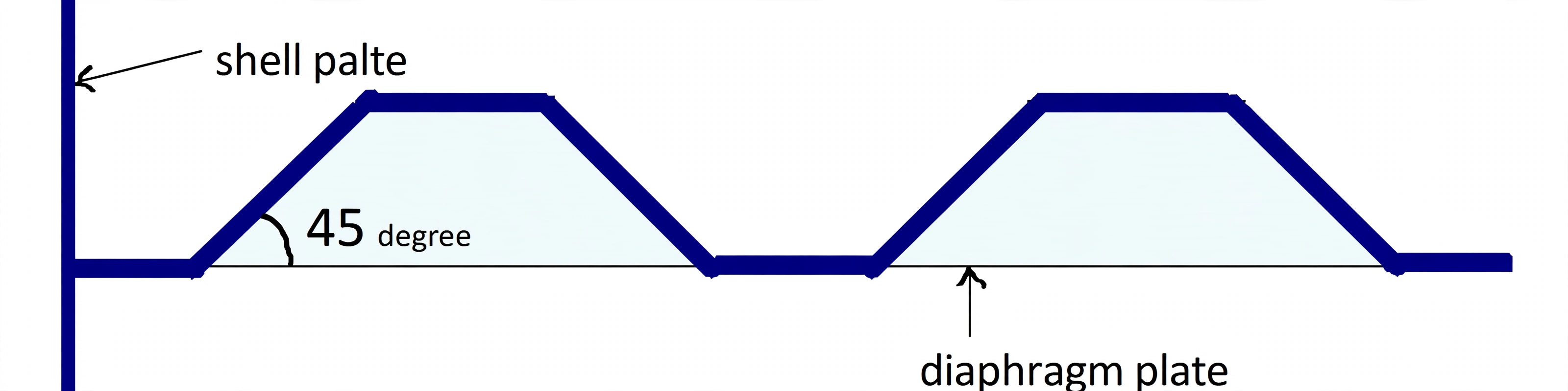
  • Corrugated bulkheads eliminate welded vertical stiffeners by pressing the plate into 45-degree trapezoidal swedges, saving 10% to 15% steel weight and facilitating tank cleaning.
  • Classification societies test watertight bulkhead integrity using a High-Pressure Hose Test (minimum 2.0 bar / 200 kPa jet from 1.5m) or Hydrostatic Head fill testing.

1. The Collision Bulkhead: The Foremost Line of Defense

In a head-on collision or severe grounding, the ship's bow absorbs tremendous kinetic energy. The Collision Bulkhead is the heaviest and most critical watertight transverse partition on board, designed to keep the vessel afloat even if the entire stem structure forward is ripped open.

The SOLAS Positioning Window: 0.05L to 0.08L

Classification societies and SOLAS strictly mandate that the collision bulkhead must be situated:

  • Not less than 0.05L (1/20th of ship length) abaft the Forward Perpendicular (FP). If placed too far forward, it will be crushed and breached during the initial bow crumpling impact.
  • Not more than 0.075L (or 0.08L / 0.05L + 3m for passenger vessels) abaft the FP. If placed too far aft, flooding the fore peak compartment would cause an extreme forward trim (trim by the head), submerging the bow and risking progressive downflooding.

The collision bulkhead must extend continuously from the keel up to the uppermost continuous deck (the Bulkhead Deck). To safeguard its watertight integrity, no doors, access manholes, or ventilation ducts are permitted through it below the bulkhead deck. Only a single pipe penetration (for fore peak ballast) is allowed, fitted with a heavy screw-down valve operable directly from above the freeboard deck.

Brain-hook for the surveyor: the collision bulkhead is not just better placed — it is built 20% stronger than every other watertight bulkhead (heavier plate plus deeper stiffeners), because it must stand after the bow crumple zone ahead of it is destroyed.

+20% SCANTLINGS STANDARD COLLISION +20% heavier plate absorbs bow impact saves the ship
Figure 1: Collision bulkhead strength margin. Built 20% stronger than standard watertight bulkheads — heavier plate and deeper stiffeners that absorb the bow impact and save the ship.
COLLISION BULKHEAD: SOLAS POSITIONING ENVELOPE (0.05L TO 0.08L) Mandatory positioning abaft the Forward Perpendicular (FP) to prevent catastrophic flooding Loaded Waterline (WL) BULKHEAD DECK (Continuous to Upper Deck) FP (Forward Perpendicular) PERMITTED ZONE COLLISION BULKHEAD Crumple Zone Min: 0.05 L (L/20) Max: 0.08 L (0.05L + 3m) Fore Peak Tank NO. 1 CARGO HOLD (Protected Dry Space) CRITICAL PENETRATION RESTRICTIONS (SOLAS CH. II-1) • ZERO doors, manholes, or ventilation ducts below bulkhead deck • Only ONE forepeak suction pipe allowed • Must be fitted with a screw-down valve operable directly from above the freeboard deck.
Figure 2: Collision Bulkhead Positioning Envelope. Mandated between 0.05L (1/20th length) and 0.08L abaft the forward perpendicular (FP). Placing it ahead of 0.05L risks crushing in bow ramming; placing it abaft 0.08L risks extreme forward trim by the head if flooded. Extending continuously to the bulkhead deck, it features zero doors or access manholes.

2. Ship Subdivision Architecture: The 4 Mandatory Bulkheads

International safety standards require every ocean-going cargo vessel to have a minimum number of transverse watertight bulkheads. These partitions restrict flooding to the damaged zone, preserve reserve buoyancy, and provide essential transverse racking strength.

The 4 Universally Mandatory Watertight Bulkheads:

1
Collision Bulkhead: Located 0.05L to 0.08L from the stem, protecting the cargo spaces from bow ramming and ice damage.
2
After Peak Bulkhead: Encloses the stern tube and rudder trunk in a watertight compartment, preventing stern tube gland failure from flooding the engine room.
3
Forward Machinery Space Bulkhead: Isolates the engine room from the cargo hold compartments forward.
4
After Machinery Space Bulkhead: Isolates the engine room from the cargo holds aft (or shaft tunnel space).
SUBDIVISION ARCHITECTURE: THE 4 MANDATORY WATERTIGHT BULKHEADS Minimum regulatory transverse subdivision required on all cargo ships 1. COLLISION B/H 3. FWD E/R B/H 4. AFT E/R B/H 2. AFT PEAK B/H Cargo Hold Subdivision Fore Peak Hold No. 2 Hold No. 1 ENGINE ROOM Aft Peak SUBDIVISION SCALING RULES (SHIPS > 90 METERS) • Total bulkheads depend on ship length L and whether machinery space is amidships or aft • Example: Ship L = 140m requires 7 bulkheads (engine amidships) or 6 bulkheads (engine aft)
Figure 3: Transverse Subdivision & The 4 Mandatory Bulkheads. Regardless of ship size, SOLAS requires at least four watertight bulkheads: the Collision Bulkhead forward, the Aft Peak Bulkhead enclosing the stern tube, and the forward and aft Machinery Space bulkheads. Intermediate cargo hold bulkheads are added according to vessel length.

3. Corrugated Bulkheads: Eliminating Stiffeners & Saving Steel Weight

Traditional watertight bulkheads are constructed from flat steel plates reinforced with heavy vertical stiffeners (angle bars, bulb flats, or welded T-sections) spaced roughly 600 mm to 800 mm apart. While structurally sound, they add significant deadweight and create structural "shadows" where cargo and oil cling.

Modern bulk carriers and chemical/oil tankers widely adopt Corrugated (Swedged) Bulkheads, where the plating itself is pressed into a series of alternating 45-degree trapezoidal waves:

10% to 15% Steel Weight Saving

The geometric depth of the corrugation provides immense intrinsic section modulus and bending stiffness, completely eliminating the need for welded vertical stiffeners and horizontal girders.

Smooth Drainage & Easy Tank Cleaning

Without hundreds of welded stiffener brackets, cargo holds and oil tanks feature smooth surfaces that drain freely, drastically accelerating hold washing and tank stripping.

Corrugation Orientation Rule

Transverse Bulkheads: Corrugations are aligned vertically to support deck loads and resist hydrostatic head pressure.

Longitudinal Bulkheads: Corrugations must run horizontally so that the steel folds participate directly in resisting global hull-girder longitudinal bending (hogging and sagging).
1. PLAIN STIFFENED BULKHEAD Flat plate + welded vertical stiffeners + heavy weight Flat Plate Boundary Welded Vertical T-Stiffeners (Heavy) PLAIN BULKHEAD LIMITATIONS • Requires extensive welding of vertical stiffener bars • Stiffener angles create traps for cargo & residue • Highest steel weight profile 2. CORRUGATED (SWEDGED) BULKHEAD Intrinsic bending stiffness • -15% steel weight • 45° folds ≈ 45° ≈ 45° Depth Self-Supporting Plate (Zero Stiffeners!) ENGINEERING SUPERIORITY • Geometric depth provides full section modulus (Z) • 10%–15% steel savings cuts ship lightweight • Smooth tank surface accelerates hold washing
Figure 4: Plain Stiffened vs. Corrugated Bulkhead Geometry. Plain bulkheads (left) rely on heavy welded vertical stiffeners. Corrugated bulkheads (right) are pressed into 45-degree trapezoidal swedges, providing high intrinsic bending modulus that eliminates welded stiffeners, cuts steel weight by 10%–15%, and provides smooth surfaces for rapid hold cleaning.
Corrugated bulkhead with trapezoidal swedges
Photo: Corrugated bulkhead — pressed 45-degree trapezoidal swedges providing intrinsic stiffness without welded stiffeners.

4. Watertight Penetrations & Surveyor Testing Protocols

A watertight bulkhead is only as reliable as its penetrations. Whenever essential services (propeller shafting, ballast piping, electrical cables) pass through a transverse bulkhead, specialized watertight glands and transits must preserve the partition's flood boundary.

Surveyor Testing Methods for Watertight Bulkheads:

1
The High-Pressure Hose Test (SOLAS Standard): A dedicated water jet directed at all welded seams and penetrations from a nozzle of at least 12 mm diameter, delivering a minimum pressure of 2.0 bar (200 kPa) from a maximum distance of 1.5 meters. The reverse side is inspected for any water weeping or seepage.
2
Hydrostatic Head Testing: For deep tanks and peak bulkheads, the compartment is filled with water to a head level reaching the deepest load waterline or the top of the air pipe, confirming strength under full flood pressure.
SURVEYOR TESTING PROTOCOL: HIGH-PRESSURE WATERTIGHT HOSE TEST Mandatory classification procedure verifying watertight seam and penetration integrity Watertight Bulkhead Plate Welded Seam / Penetration Gland Fire Hose Line Nozzle ≥ 12 mm Water Jet ≥ 2.0 bar (200 kPa) Max Distance ≤ 1.5 m INSPECTION Reverse Side Must Remain 100% DRY SURVEYOR TESTING ACCEPTANCE CRITERIA Nozzle ≥ 12 mm • Pressure ≥ 2.0 bar (200 kPa) • Distance ≤ 1.5 m • Zero water drops or chalk dusting transfer permitted on reverse face.
Figure 5: Watertight Bulkhead Testing Protocol. Classification societies mandate a high-pressure hose test for all watertight bulkhead boundaries. A water jet with minimum 2.0 bar pressure (from a 12 mm nozzle at no more than 1.5 m distance) is played across all seams, penetrations, and glands; the reverse side must show zero leakage or moisture.

5. Non-Watertight Bulkheads

Not every bulkhead is a flood boundary. Any bulkhead which does not form part of a tank or part of the watertight subdivision of the ship may be non-watertight.

Where They Are Fitted:

  • Many non-watertight bulkheads are fitted forming engine casings and partitions in accommodation.
  • 'Tween deck bulkheads fitted above the freeboard deck may be of non-watertight construction.
  • Many ships are fitted with partial centreline bulkheads if grain is to be carried, to restrict cargo shift.

Structural Role:

  • Centreline bulkheads and many deck-house bulkheads act as pillars supporting beams and deck girders, in which case the stiffeners are designed to carry the load.
  • The remaining bulkheads are lightly stiffened by angle bars or welded flats.
Watertight vs. Non-Watertight — The Key Point

A non-watertight bulkhead may be perfectly strong and load-bearing, but it does not resist a head of water and is not part of the subdivision that keeps a flooded ship afloat. Only watertight bulkheads provide reserve buoyancy and flood protection.

WATERTIGHT BULKHEAD Part of the flood subdivision WT Bulkhead Flooded side Dry side • Resists a head of water • Provides reserve buoyancy & subdivision NON-WATERTIGHT BULKHEAD Engine casing / accommodation / tween deck Deck / girders Pillar / partition Angle bar / welded flat stiffeners • Supports beams and deck girders • Does not resist water / no flood boundary
Figure 6: Non-Watertight Bulkheads. Unlike a watertight bulkhead (left), a non-watertight bulkhead (right) forms engine casings, accommodation partitions, tween-deck bulkheads or partial centreline bulkheads, and often acts as a pillar supporting beams and deck girders.