How ships survive violent wave slamming and pulsating hydrodynamic pressure with heavy structural reinforcements.
7 min read
Intermediate
Ship Construction & Naval Architecture
Key Principles at a Glance6 points
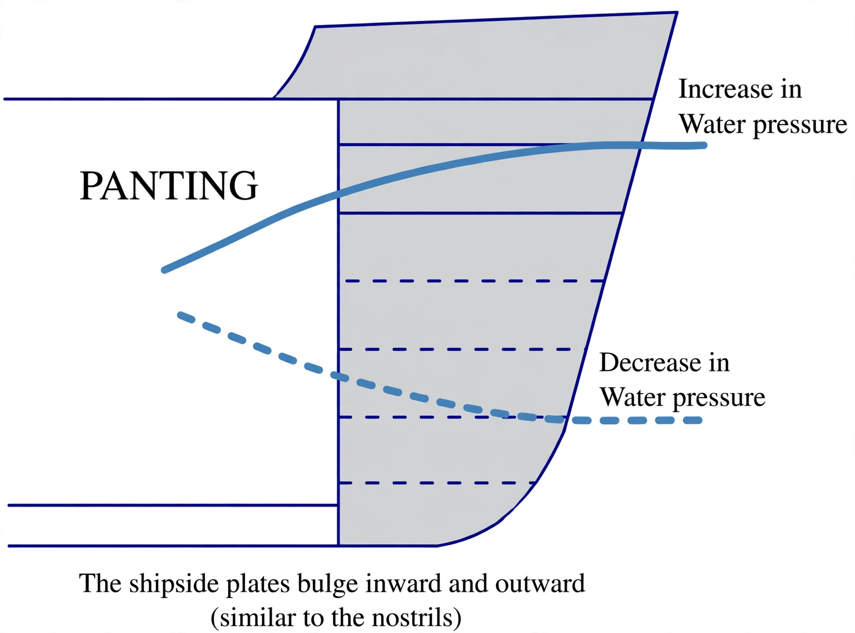
Panting is the pulsating, bellows-like in-and-out flexing of shell plating caused by rapid hydrostatic pressure variations as wave crests and troughs sweep past the hull ends.
Panting forces are most severe in the forward 15% of the ship (the fore peak) and abaft the after-peak bulkhead.
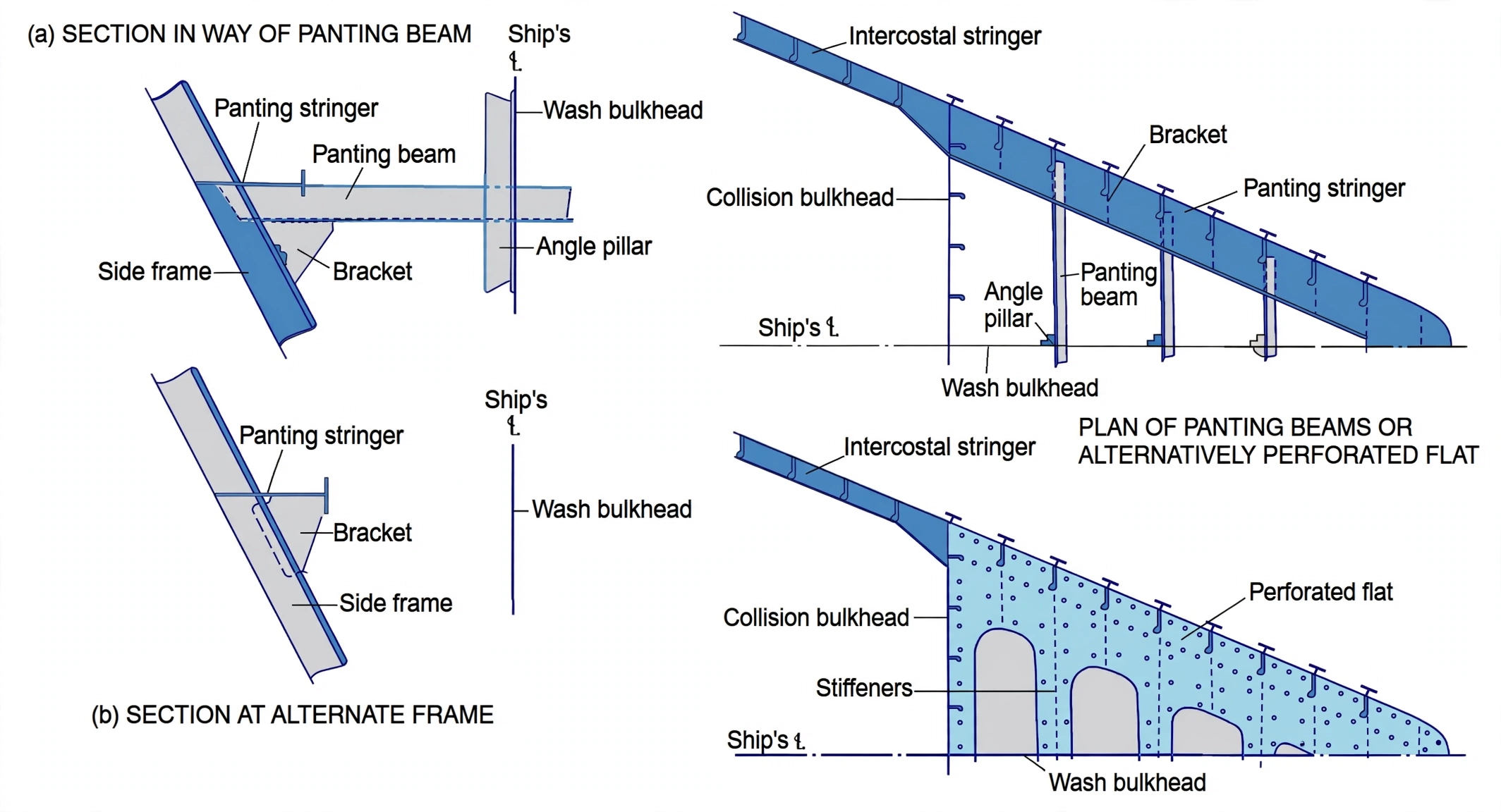
To resist panting, naval architects fit: Panting stringers (horizontal longitudinal girders spaced every 2m), Panting beams (transverse cross-ties), and Breast hooks (triangular gusset plates bridging the stem).
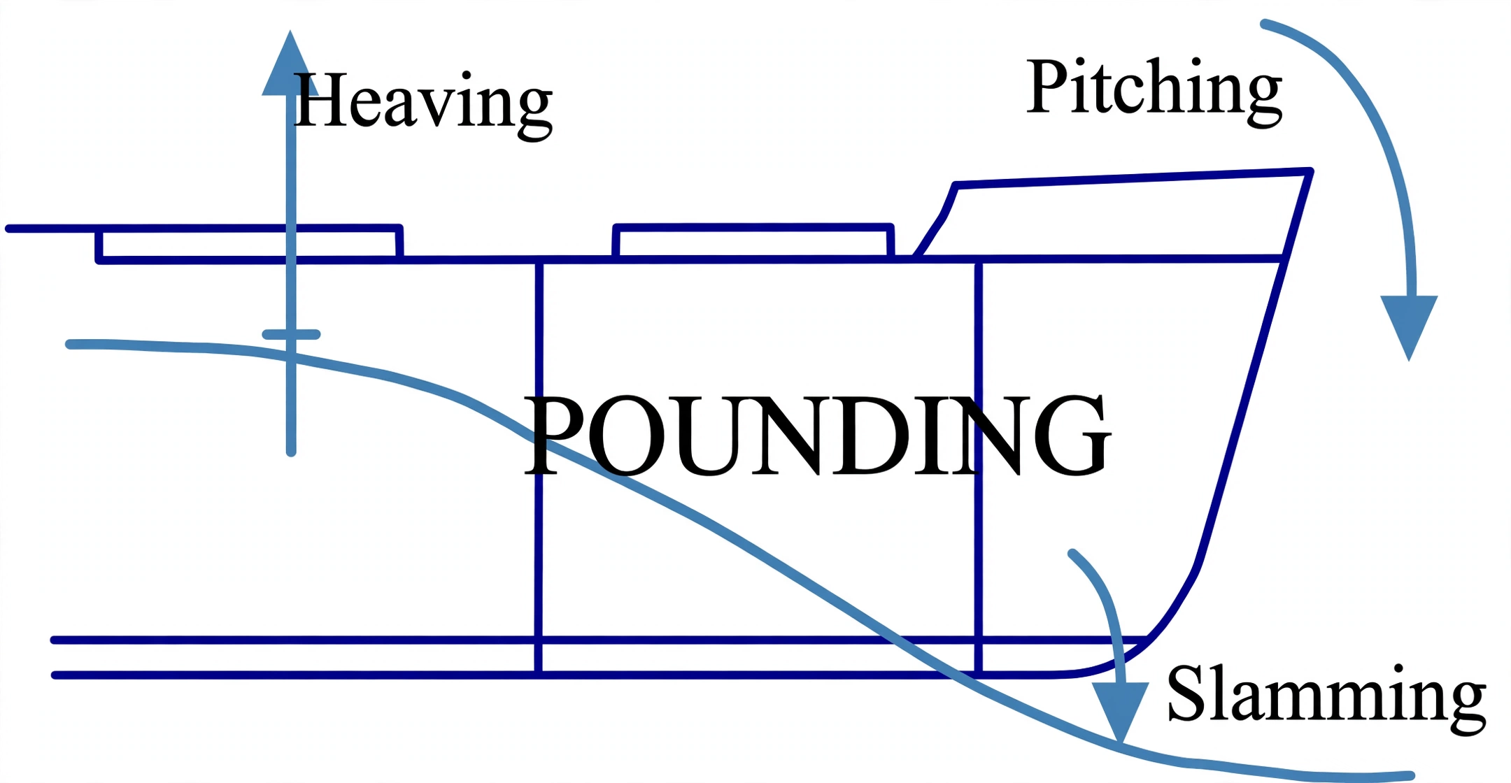
Pounding (Bottom Slamming) occurs when severe pitching causes the forefoot to rise completely out of the sea and crash down into an oncoming wave trough with devastating shock loads.
Pounding damage is concentrated on the flat bottom between 0.05L and 0.25L–0.30L from the forward perpendicular.
To resist pounding, the forward double bottom is heavily reinforced with solid plate floors at EVERY frame space (continuously welded), intercostal side girders, and thickened bottom plating.
1. Two Distinct Dynamic Stresses at the Ship Ends
While calm-water stresses are predictable, the open ocean subjects a ship's bow and stern to intense cyclic loads. Two of the most destructive localized phenomena are Panting and Pounding:
Panting (Bellows Breathing)
A continuous, rhythmic in-and-out flexing of the side shell plating at the bow and stern. Driven by alternating high pressure (wave crest) and low pressure (wave trough) cycling as the ship pushes through waves.
Pounding (Bottom Slamming)
A violent, high-impact hammer blow against the flat bottom plating forward. Occurs when synchronised pitching lifts the bow clear of the water, followed by an explosive re-entry into the sea surface.
Figure 1: The Two Dynamic Stresses at Ship Ends. Panting (left) is the continuous, bellows-like in-and-out flexing of bow side shell plating driven by rapid hydrostatic head changes between wave crests (+P) and troughs (-P). Pounding (right) occurs when synchronized pitching thrusts the flat bottom forward out of the water, followed by an explosive re-entry impact (300 to 500 kPa).
Figure: Panting pressure — alternating crest and trough heads flexing the bow shell in and out.
2. Panting & Pounding: The Internal Structural Skeleton
Because the bow shell plating is relatively flat and flares outward, hydrostatic head pressure changes drastically between wave crests (deep immersion → high external pressure pushing steel inward) and wave troughs (low immersion → steel springing outward).
Without internal bracing, this cyclic breathing would cause metal fatigue and weld failure within weeks. To lock the bow rigid, shipbuilders construct a specialized internal skeleton within the forward 15% of ship length:
1
Panting Stringers: Heavy horizontal longitudinal girders welded to the inner face of the side frames at vertical intervals of roughly 2.0 meters below the lowest deck.
2
Panting Beams: Transverse structural cross-members spanning between port and starboard panting stringers forward of the collision bulkhead to resist inward crushing.
3
Breast Hooks: Heavy triangular horizontal steel gusset plates fitted at the stem. They tie the port and starboard panting stringers together into a unified, rigid wedge.
4
Perforated Wash Flats: Horizontal deck flats with large lightening holes that provide lateral stiffness while allowing water and ballast to flow freely.
Interactive 3D: Fore Peak Structural Skeleton
Orbit the model, select any component to isolate it, then switch on the Panting and Pounding loads to watch how the steel skeleton fights back.
Loading interactive 3D fore peak model…
Figure 2: Fore Peak Panting Structural Skeleton. Shows the internal reinforcing framework: horizontal Panting Stringers spaced vertically at ~2.0 m intervals, cross-ship Panting Beams resisting inward hull crushing, and triangular Breast Hooks anchoring the stringers solidly into the stem bar.
Figure: Panting beams in the forepeak — transverse ties between panting stringers with breast hooks at the stem.
Pounding occurs in heavy weather when the frequency of ship pitching synchronizes with the encounter frequency of oncoming storm swell. The bow heaves up into the air, exposes its flat bottom, and crashes into the water with pressures exceeding 300 to 500 kPa.
The Pounding Region: 0.05L to 0.30L Forward
Classification societies require all ships exceeding 65 meters in length to install specialized pounding reinforcement over the bottom plating between 5% and 30% of ship length abaft the stem.
Structural Defenses Against Bottom Slamming:
Solid Plate Floors at EVERY Frame: In the midship cargo holds, solid floors are often fitted every 3 or 4 frames with open bracket floors in between. In the pounding region, solid plate floors are mandated at every single frame space.
Continuous Submerged Welding: Floors are joined to the outer bottom shell plating with continuous double-sided welds (no intermittent or staggered stitches).
Longitudinal Side Girders: Additional intercostal side girders are fitted no more than 2.2 meters apart, running vertically from the bottom shell right up to the tank top plating.
Thickened Bottom Plating: The outer keel and bottom strakes in this zone are increased in plate thickness to prevent denting and dishing between frames.
Figure 3: Pounding Region (0.05L to 0.30L) Bottom Reinforcement. Bottom slamming stresses are concentrated on the forward flat bottom. To prevent plate dishing and floor buckling, classification societies mandate solid plate floors at every frame space, intercostal side girders spaced $le 2.2, ext{m}$, and thickened shell strakes.
Figure: Pounding — bow heave and slam impact on the 0.05L to 0.30L flat bottom.
Panting stringers (2m spacing), panting beams, breast hooks
Solid floors at every frame, 2.2m side girders, continuous welds
Figure 4: Shipboard Zonal Distribution of Dynamic Stresses. Panting stresses (blue) threaten the flared bow and cruiser stern, defended by internal stringers, beams, and breast hooks. Pounding stresses (red) attack the forward flat bottom between 0.05L and 0.30L, defended by solid plate floors at every frame.