Ship Dimensions & Basic Naval Architecture Definitions
The surveyor's vocabulary: principal dimensions, form coefficients, propeller slip terms, and hull plating names.
Key Principles at a Glance 6 points
- Principal dimensions include Length Overall (extreme fore to aft), Length Between Perpendiculars (used for calculations), breadth extreme/moulded, depth extreme/moulded and draught extreme/moulded.
- Freeboard is the distance from the waterline to the top of the deck plating at the side amidships, and represents the vessel's safety margin.
- Form coefficients describe hull shape: waterplane area (Cw), midship section (Cm), block (Cb) and prismatic (Cp) coefficients.
- Hydrostatic terms include Archimedes' principle, displacement, TPC = (waterplane area × density)/100, centres of gravity and buoyancy, metacentric height and reserve buoyancy.
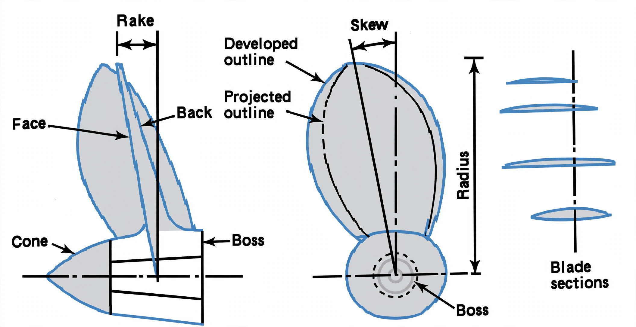
- Propeller terms describe slip and efficiency: pitch, diameter, pitch ratio, theoretical speed, wake, wake fraction, speed of advance, real slip, apparent slip and skew.
- Hull plating terms include strake, garboard strake, bilge strake, sheer strake, stealer strake, stringer, margin plate, coffin plate, shoe plate, bulwark, freeing port and gunwale.
1. Principal Dimensions & Hull Form
Idea in one line: three lengths, one breadth and a depth-equals-draught-plus-freeboard rule fix every number the surveyor will ask for.
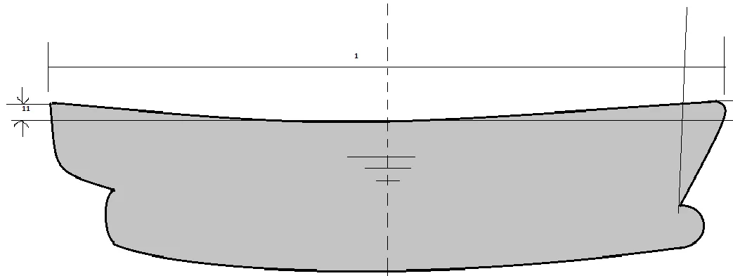
- Length overall (LOA): The distance from the extreme fore part of the ship to a similar point aft — the greatest length of the ship. Important when docking.
- Length between perpendiculars (LBP): The fore perpendicular is where the Summer Load Waterline crosses the stem; the after perpendicular is the after side of the rudder post (or the centre of the rudder stock if no rudder post). The distance between them is used for ship calculations.
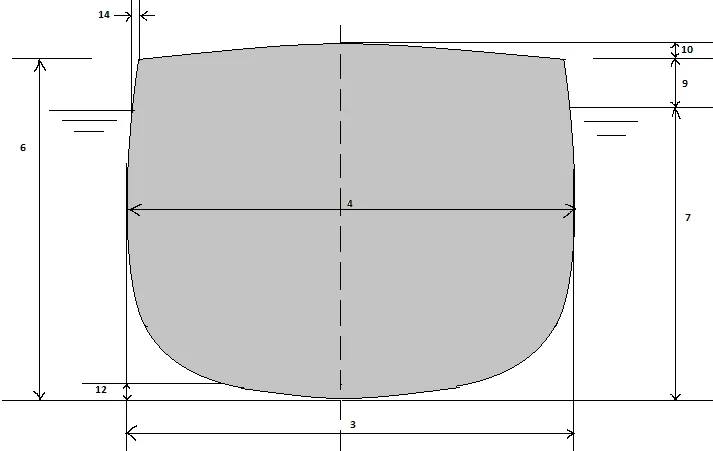
- Breadth extreme: The greatest breadth measured to the outside of the shell plating.
- Breadth moulded: The greatest breadth measured to the inside of the shell plating.
- Depth extreme: Depth from the underside of the keel to the top of the deck beam at the side of the uppermost continuous deck amidships.
- Depth moulded: The depth measured from the top of the keel.
- Draught extreme: Distance from the bottom of the keel to the waterline (load draught = maximum permitted).
- Draught moulded: The draught measured from the top of the keel to the waterline.
- Freeboard: Distance from the waterline to the top of the deck plating at the side amidships. It is the safety margin showing to what depth a ship may be loaded. Its purpose is to ensure she cannot be loaded beyond her strength, to provide adequate reserve buoyancy, and to keep the deck high enough for the crew to work.
- Camber (round of beam): The transverse curvature of the deck from centreline down to the sides, to drain water to the sides.
- Sheer: The curvature of the deck fore and aft, rising from amidships to a maximum at the ends. Sheer forward is usually twice that aft; it makes a ship more seaworthy.
- Rise of floor: The bottom shell is sometimes sloped up from the keel to the bilge to aid drainage (150 mm is usual).
- Bilge radius: The radius of the arc connecting the side to the bottom at the midship portion.
- Tumblehome: Where the midship side shell near the upper deck curves inwards towards the centreline, reducing the upper deck width.
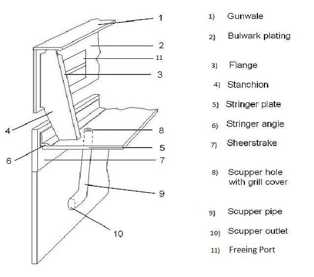
- Bulwark: A solid wall extending above an exposed deck for the safety of the crew (at least 1 m high; stay spacing not exceeding 1.2 m on the forecastle).
- Gunwale: The upper edge of the ship's side where the sheer strake meets the deck plating.
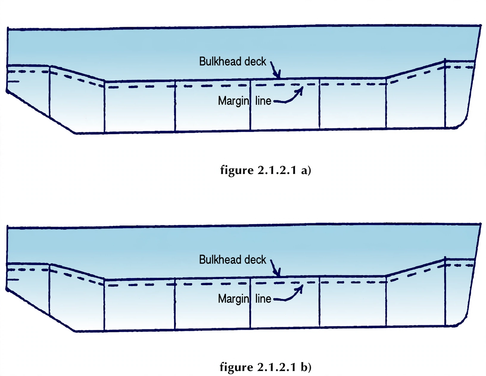
- Margin line: An imaginary line drawn at least 76 mm below the upper surface of the bulkhead deck at side; it denotes the limit to which the ship can be flooded/loaded without sinking.
Lengths — LOA / LBP / LWL
LOA spans extreme ends for docking and berths. LBP runs AP to FP for every hydrostatic calculation. LWL is the actual immersed length on the summer waterline.
Verticals — D = d + f
Moulded depth equals draught plus freeboard. Draught pays for buoyancy; freeboard banks reserve buoyancy and keeps the deck workable for the crew.
Transverse — B, camber, sheer
Breadth sets deck area and stability. Camber sheds water off the deck; sheer lifts the ends clear of head seas.
Moulded depth (D) = draught (d) + freeboard (f). Any two fix the third — the surveyor's favourite cross-check.
Orbit the hull and pick any dimension to isolate it. Switch modes across LOA / LBP / LWL & perpendiculars, depth / draught / freeboard, breadth & midship section and sheer & camber. Use Full Screen to view the model without the side panel.
2. Hydrostatics & Form Coefficients
Idea in one line: each coefficient compares the real hull to its enclosing box, turning shape into numbers that predict sinkage, capacity and resistance.
- Archimedes' principle: If a solid body is immersed in a liquid there is an apparent loss in weight; this loss is the upthrust exerted by the liquid and is equal to the weight of the liquid displaced.
- Displacement: When a ship floats freely at rest, the mass of the ship equals the mass of the water displaced — this is the displacement.
- TPC (tonne per centimetre immersion): The mass required to increase the mean draught by 1 cm. TPC = (Aw × density) / 100.
- Metacentre (M): The point where a vertical line through the centre of buoyancy of an inclined ship intersects the vertical line through the centre of gravity in equilibrium.
- Waterplane area coefficient (Cw): Ratio of the waterplane area to the product of length and breadth.
- Midship section area coefficient (Cm): Ratio of the immersed midship area to (breadth × draught).
- Block coefficient (Cb): Ratio of the volume of displacement to (length × breadth × draught).
- Prismatic coefficient (Cp): Ratio of the volume of displacement to (length × immersed midship area).
- Wetted surface area: Area of hull in contact with water, found from transverse girths via Simpson's Rule plus a percentage for longitudinal curvature, plus appendages (cruiser stern, rudder, bilge keels). (Denny's and Taylor's equations are used.)
- Centre of gravity (G): The point at which the whole weight may be regarded as acting; if suspended there, the body balances.
- Centre of buoyancy (B): The point through which the total force of buoyancy acts.
- Metacentric height (GM): Distance between the centre of gravity and the transverse metacenter.
- Longitudinal Centre of Flotation (LCF): The point about which the ship trims when weights are loaded/discharged; if weight is added at the LCF, trim does not change — only draught changes.
- Permeability (µ): Ratio of the volume assumed occupied by water to the total volume of a compartment. µ ≈ 85% for machinery space, 95% for accommodation, 60% average for cargo hold.
- Buoyancy: The upthrust exerted by water on the ship; if floating freely, buoyancy equals the weight of the ship.
- Reserve buoyancy: The potential buoyancy depending on the intact watertight volume above the waterline; if mass is added or buoyancy lost by bilging, reserve buoyancy is converted into buoyancy by increasing draught.
| Coefficient | Formula | What it predicts |
|---|---|---|
| Cw (waterplane) | Aw ÷ (L × B) | TPC, sinkage, BM inertia |
| Cm (midship) | Am ÷ (B × d) | Section fullness, bilge radius |
| Cb (block) | ∇ ÷ (L × B × d) | Displacement, capacity, resistance |
| Cp (prismatic) | ∇ ÷ (L × Am) | End taper, wavemaking drag |
Load or discharge exactly at the Longitudinal Centre of Flotation and trim does not change — only mean draught moves. Anywhere else, the ship trims about the LCF.
TPC in one breath?
Mass to sink the ship 1 cm: waterplane area times density over 100. Big flat waterplane, big TPC.
Cb vs Cp — which answers what?
Cb answers how full the whole underwater block is; Cp answers how full the ends are for a given midship section. Finer ends, lower Cp, less wavemaking.
3. Propeller & Slip Terms
Idea in one line: the propeller is a screw in a yielding fluid — pitch times revs promises a speed the stern wake never quite lets it keep.
- Pitch of propeller: The distance the propeller will move forward in one revolution of the shaft.
- Diameter of propeller: The diameter of the circle (disc) cut out by the blade tips.
- Pitch ratio: The face pitch divided by the diameter.
- Theoretical speed (Vt): The distance the propeller would advance in unit time if working in an unyielding fluid: Vt = P × N (m/min), or Vt = (P × N × 60) / 1852 knots.
- Wake: The water which is in motion at the stern of a ship as a result of the ship's movement.
- Wake fraction: The ratio of the wake speed to the speed of advance.
- Speed of advance (Va): The speed of the ship relative to the wake.
- Real (true) slip: The difference between theoretical speed and speed of advance: Real slip = ((Vt − Va) / Vt) × 100%.
- Skew: The offset of a propeller blade from the vertical in the plane of rotation; always in the direction opposite to rotation.
- Slip: The difference between the actual distance travelled by a ship and the theoretical distance given by (pitch × revolutions), usually expressed as a percentage; can be negative with a current or following wind.
- Apparent slip: Because the propeller works in water, the ship speed V is normally less than the theoretical speed; the difference between the two speeds.
| Speed | Meaning | Slip built on it |
|---|---|---|
| Vt — theoretical | Pitch × revs in a solid medium | Baseline both slips use |
| Va — advance | Ship speed relative to stern wake | Real slip = (Vt − Va)/Vt |
| V — ship | Speed through the water | Apparent slip = (Vt − V)/Vt |
Real slip against the wake is always positive — water yields. Apparent slip against the log can turn negative with a favouring current or following sea pushing the ship faster than the screw promises.
4. Hull Plating & Structural Terms
Idea in one line: strakes are longitudinal strength members, and the thickest ones sit exactly where hull bending stress peaks.
- Strake: The external hull consists of bottom shell, side shell and deck formed by longitudinal strips of plating called strakes — a continuous range of plate extending from stem to stern.
- Bilge strake: The strake at the turn of the bilge.
- Stealer strake: Where a number of adjacent strakes are fitted together at the end of the ship.
- Garboard strake: The strake adjacent to the keel on each side of the ship.
- Sheer strake: The largest continuous strake at the top of the side, meeting the upper deck. It is 10–20% thicker than other side plating because it is subjected to maximum compressive and tensile stress during hull bending.
- Stringer: Stiffeners used to strengthen the side surface of the ship; without stringers the hull shape would not be formed.
- Coffin plate: Used to connect the stern frame to the flat plate keel.
- Shoe plate: Used to connect the stem to the flat plate keel.
- Margin plate: At the bilges, the tank top may be continued straight out to the shell by a tank margin plate — watertight and set at about 45° to the tank top, meeting the shell almost at right angles.
- Freeing port: Openings in a bulwark to let water drain; area depends on the length of the well deck, with the lower edge as near the deck as possible, protected by rails about 230 mm apart, and hinged flaps with non-corrodible hinges.
- Buttock line: An equidistant longitudinal section line from midships forward, giving the cross-section at various stations for all draughts and trims; used to find light displacement at the end of construction.
- Transom space: Situated in the steering gear room near the rudder trunk, with a manhole door for inspecting rudder trunk condition and lubrication; entry only in port in calm weather.
Frame & Plate Numbering — Reading the Shell Expansion Plan:
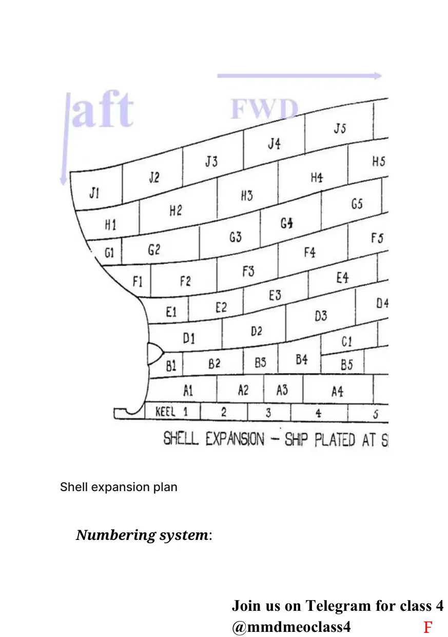
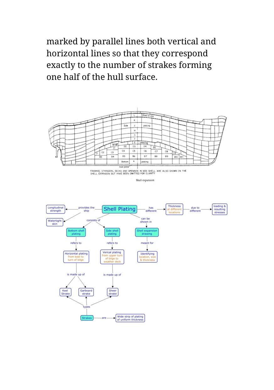
- What it is: a two-dimensional drawing of the three-dimensional hull surface, developed from the ship's lines plan — contour lines erected straight on a base line representing the ship's length at the stations of their frame numbers, joined into the shell outline, then ruled with vertical and horizontal lines matching exactly the strakes of one half of the hull.
- Frames: numbered from Frame 0 at the rudder stock, counting forward to the stem; plans mark every 5th frame. Frames abaft Frame 0 count negative (rudder stock is not the aftermost part). Spacing 600–950 mm — close enough that every part stays reachable for inspection and maintenance, wide enough for a welder to weld properly.
- Strakes (athwartship): read off the half-breadth plan — keel strake on the centreline (half to port, half to starboard), then Garboard = A, B, C… up to the sheer strake (topmost side strake), lettered upward.
- Plates (lengthwise): counted aft → forward in numbers — each plate is a letter (level) + number (position), e.g. the aft-to-forward run of B-strake reads B1, B2, B3…
Shell strakes
Sheer strake on top (10–20% thicker for bending), bilge strake round the turn, garboard strake flanking the keel, stealers gathering the ends.
Inner bottom
Tank top plus margin plate at about 45° close the double bottom at the bilges; centre girder and stringers carry the longitudinal load.
Ends & openings
Shoe plate joins stem to keel, coffin plate joins stern frame to keel, freeing ports shed shipped seas off the well deck.
Hogging and sagging put peak tension and compression at the deck edge amidships. The sheer strake lives exactly there — extra thickness is extra beam flange.