Rudder Construction & The Rudder Carrier Bearing
Conical thrust faces, rudder stock support, balanced vs. flap rudders, trammel gauge wear-down, and jumping clearances.
Key Principles at a Glance 6 points
- The rudder carrier bearing supports 100% of the vertical deadweight of the rudder blade and stock on the steering gear flat, while accommodating horizontal steering torque and side loads.
- Carrier bearings feature a conical (tapered) thrust face rather than a flat face, providing three critical engineering benefits: self-centering (prevents horizontal sideslip), larger projected contact area, and superior lubricant retention.
- Balanced rudders place 25% to 30% of the blade area forward of the turning axis, shifting the center of pressure close to the stock to drastically reduce the required steering gear torque.
- The rudder trunk houses the rudder stock through the hull, fitted with a watertight stuffing box/gland; the adjacent transom space provides surveyor access for seal and trunk inspection.
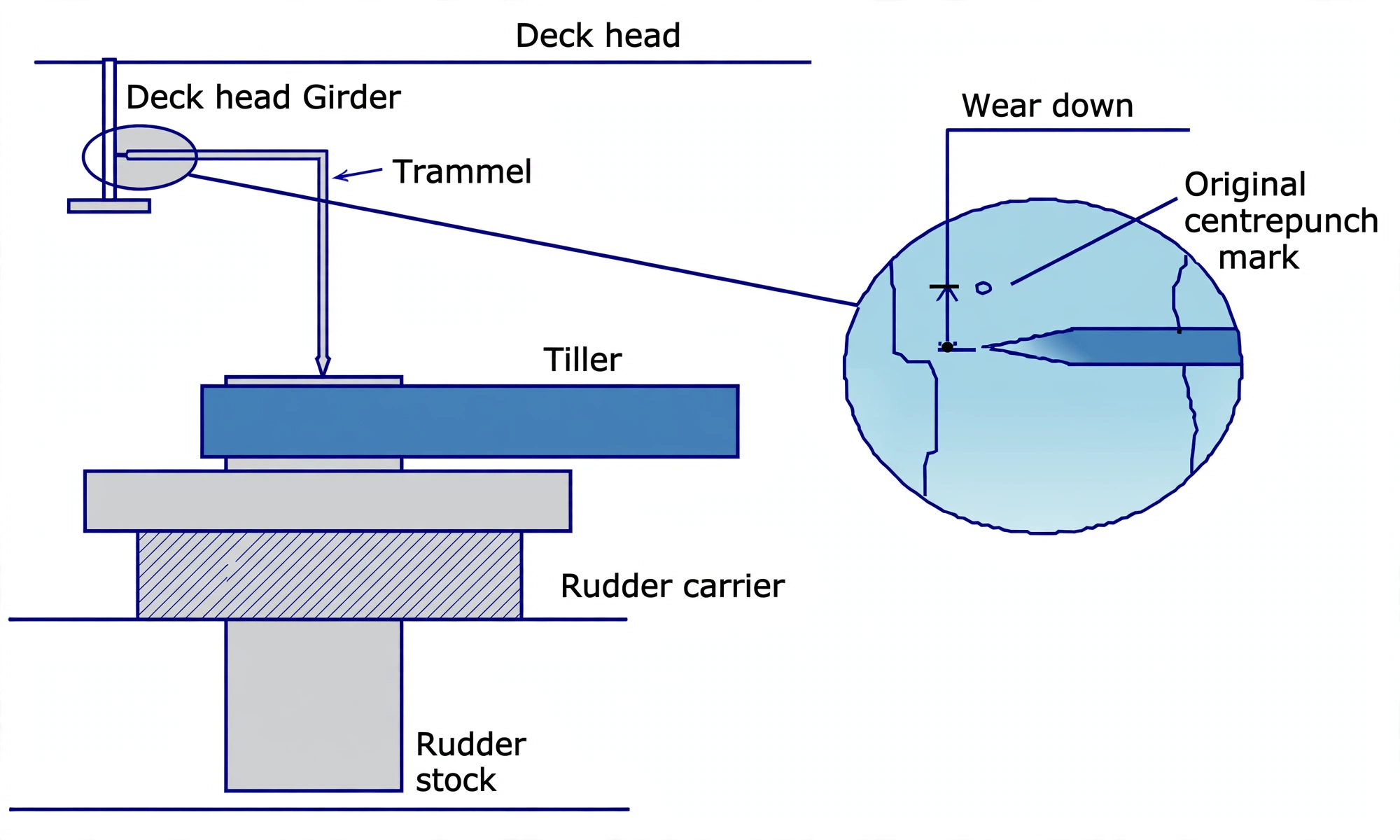
- Vertical wear-down (rudder drop) is accurately measured during drydock and at sea using a rigid L-shaped Trammel Gauge referenced against permanent center-punch marks on the stock and deck girder.
- Solid steel jumping stops welded to the stern frame prevent the rudder from leaping upward due to heavy wave impact (designed jumping clearance is typically 19 mm).
1. Rudder Types & Hydrodynamic Torque Balancing
A ship rudder is a streamlined hydrofoil that deflects the propeller slipstream to generate transverse lift, creating a turning moment about the vessel's center of gravity. Rudders are classified by how their surface area is distributed relative to the centerline turning axis (the stock axis):
1. Balanced Rudder
25% to 30% of total blade area is situated forward of the turning axis, with 70% to 75% aft. The forward area creates a counter-acting turning moment that moves the hydrodynamic center of effort directly over the stock, slashing the required steering gear motor torque by up to 70%.
2. Semi-Balanced (Horn) Rudder
Supported by a heavy fixed cantilever rudder horn projecting down from the stern frame. Only the lower portion of the rudder blade extends forward of the axis (typically 15% to 20% area), while the upper portion is hinged behind the horn.
3. High-Lift Flap Rudder (Becker Type)
Features an articulated trailing-edge flap mechanically linked to the main blade. When the main rudder turns to 35°, the tail flap rotates a further 10° (total 45° camber), preventing flow stall and generating extreme turning forces at dead-slow maneuvering speeds.
2. The Rudder Carrier Bearing: Conical Thrust Face & Journal Support
The entire combined deadweight of the rudder blade, internal framing, and vertical rudder stock (often exceeding 50 to 100 metric tons on large vessels) is supported on the Steering Gear Flat by a specialized heavy-duty bearing called the Rudder Carrier Bearing.
Why the Thrust Face is Conical (Tapered):
In oral exams, surveyors routinely ask: "Why is the thrust bearing surface of a rudder carrier conical rather than flat?" The engineering rationale encompasses three distinct advantages:
- Self-Centering Action (Eliminates Sideslip): A flat horizontal thrust plate could allow the massive stock to slide transversely under wave impact. The conical taper (typically angled at 30° to 45°) naturally wedges and centers the rudder stock on the rotational axis, preventing lateral movement.
- Increased Projected Bearing Surface: For a given shaft diameter, a cone possesses a significantly larger surface area than a flat ring ($A_{\text{cone}} = \pi r s$). This distributes the multi-ton vertical deadweight over a larger area, lowering the compressive stress ($\text{N/mm}^2$) and allowing a more compact housing.
- Superior Lubricant Retention: Grease pumped into the conical interface cannot easily escape. Centrifugal action and gravity retain water-resistant graphite grease along the conical contact zone, preventing metal-to-metal galling.
Materials & Structural Mounting:
The carrier housing is cast from high-grade Meehanite iron, fitted with a split gunmetal (or aluminum-bronze) thrust ring and a synthetic or phosphor-bronze journal bush. The bearing is split into two halves to facilitate in-situ replacement without unshipping the stock. To transfer immense transverse steering forces into the ship hull, the housing rests upon a heavy doubler plate and is locked firmly into position by welded wedge chocks secured to the deck stiffening.
3. Rudder Trunk, Transom Space & Watertight Glands
Between the underwater rudder blade and the steering gear flat, the rudder stock must penetrate the ship's bottom shell. This penetration is enclosed within a reinforced vertical compartment known as the Rudder Trunk.
Construction of the Rudder Trunk:
- Structural Tube: A heavy watertight steel cylinder extending from the stern frame up to the steering flat deckhead. It is stiffened by horizontal diaphragms and bracketed to transverse floors in the aft peak.
- Watertight Gland (Stuffing Box): At the top of the rudder trunk, a watertight packing gland or lip seal prevents seawater from flooding into the steering gear room. Because the stock rotates, the gland is packed with grease-impregnated PTFE or synthetic packing compressed by a bolted gland follower.
Situated in the steering gear room at the very stern of the ship is a small access void known as the Transom Space. Inside, a watertight manhole door allows engineers and surveyors to enter the compartment:
- Purpose: Allows visual inspection of the rudder trunk plating, gland condition, packing tightness, and grease lubrication lines.
- Safety Mandate: Entry into the transom space is strictly permitted in port only and during calm weather or sheltered anchorages. At sea, extreme wave action against the stern frame creates severe dynamic pressures, making entry hazardous.
4. Wear-Down Measurements: The Trammel Gauge & Jumping Stops
Because the rudder carrier bearing supports immense vertical weight and endures constant oscillations, the gunmetal thrust ring gradually wears down over thousands of operating hours. If wear becomes excessive, the rudder drops, misaligning the steering gear actuator rams and risking catastrophic binding.
Measuring Rudder Drop with the "Trammel Gauge":
Surveyors monitor bearing wear during annual surveys and drydockings using a dedicated L-shaped Trammel Gauge:
- Original Datum Points: When the vessel is brand new, distinct center-punch marks are stamped at two permanent locations: one onto the rudder stock, and a mating reference punch mark on a fixed structural deck girder directly above.
- The Fixed Trammel: A rigid, heat-treated L-shaped steel rod is precision-machined to span exactly between these two punch marks in the "as-new" condition.
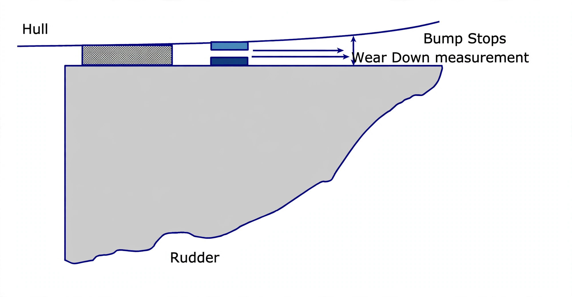
- Measuring the Drop: During subsequent drydock inspections, the lower pointer of the trammel gauge is seated in the stock punch mark. As the carrier bearing wears, the upper pointer will fall below the girder mark by a measurable gap. This difference is the exact Rudder Wear-Down (Rudder Drop). The same drop can be read between pads welded on top of the rudder and on the rudder horn.
- Statutory Limit: Classification rules typically permit a maximum wear-down of 12 mm to 19 mm (depending on vessel deadweight and steering gear type). Exceeding this limit requires lifting the stock and renewing the bronze thrust ring. On a ram-type gear at sea, read two fork-end gaps instead: jumping (bouncing) clearance between swivel block and upper ram fork end — limit 19 mm; wear-down clearance between swivel block and bottom ram fork end — limit 12–19 mm. At docking, read bouncing clearance between top of rudder and jumping bar and wear-down clearance between bottom of rudder and reference mark.
Jumping Stops & Bouncing Clearance:
In heavy storm seas, an upward buoyant wave shock or severe stern pitching slam can fling the multi-ton rudder vertically upward. To prevent the rudder stock from crashing into the steering gear actuators:
- Jumping Stops (Rudder Stops): Solid steel stop blocks are welded to the stern frame directly above the top edge of the rudder blade.
- Bouncing Clearance (Jumping Clearance): The vertical air gap between the top of the rudder blade and the jumping stops is carefully gauged (typically maximum 19 mm).
- The Wear Relationship: As the rudder carrier bearing wears down over time, the jumping clearance increases proportionally! This is why jumping clearances are always checked in conjunction with wear-down during docking surveys.