
Chain Locker, Bitter End & Anchor Cable Arrangement
Where the chain is stowed, how the bitter end is secured, and the spurling/hawse pipe path that leads the cable to the water.
Key Principles at a Glance 6 points
- The chain locker is fitted between the upper and second deck, below the second deck, or in the forecastle; it is usually forward of the collision bulkhead, is not carried out to the ship's side, and must have sufficient volume to allow adequate headroom with the anchors stowed.
- The spurling pipe (chain pipe) connects the chain locker to the deck, while the hawse pipe runs from the deck to the hull of the ship; a fire hose line in the hawse pipe cleans mud off the chain as it comes from the water.
- The top of the chain or spurling pipe has a canvas sleeve to keep water from entering the chain locker, and any fluid accumulated is removed by an eductor for direct discharge overboard.
- A chain stopper, fastened with a hinged lever, locks the chain in any desired position and releases load from the windlass when the anchor is out or stowed; cable lifters are arranged over the spurling pipe to give a direct lead for the cable into the locker.
- The bitter end is the end of the chain secured in the chain locker, attached to the hull by a quick-release mechanism; the end link slides between horizontal bars on the collision bulkhead and is secured by a bolt.
- A centreline division separates the two cables (port and starboard), stiffeners are fitted outside the locker to prevent chain damage, and a false floor with a drain plug in the forward bulkhead allows mud and water to drain.
1. Chain Locker: Location & Purpose
The chain locker is the compartment in which the anchor cable is stowed when the anchor is housed.
Location:
- Fitted between the upper and second deck, below the second deck, or in the forecastle.
- Usually forward of the collision bulkhead.
- It is not carried out to the ship's side (it is kept inboard).
- It must have sufficient volume to allow adequate headroom when the anchors are in the stowed position.
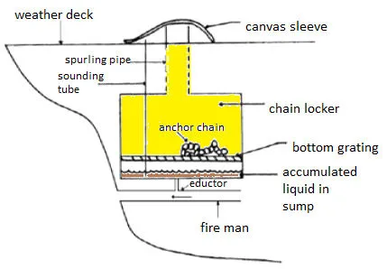
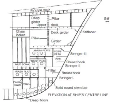
Location & Arrangement
- Positioned strictly forward of the collision bulkhead
- Fitted between upper deck and second deck, or in forecastle
- Kept inboard from outer shell plating to resist damage
- Direct vertical fall directly below the windlass gypsy
Watertight Subdivision
- Anchor cable surge cannot breach cargo hold boundaries
- Collision bulkhead boundary remains intact & untruncated
- Boundary plating is fully seal-welded throughout
- Stiffeners placed externally to prevent flailing link impacts
Capacity & Drainage
- Tall, deep geometry promotes natural self-stowing
- Generous headroom maintained above stowed cable piles
- Centreline division prevents port and starboard tangles
- Perforated false floor drains mud slurry to the sump eductor
Orbit the bow and select any part to isolate it. Switch modes across the Anchor to Locker Run, Spurling & Hawse Pipes, Bitter-End Release and Stowage & Drainage. Use Full Screen to view the model without the side panel.
2. Construction & Connections: Spurling Pipe, Hawse Pipe & Fittings
- Spurling pipe (chain pipe): Connects the chain locker to the deck, guiding the cable down into the locker.
- Hawse pipe: Runs from the deck to the hull of the ship; when the anchor chain comes out of the sea (S.W.) with mud stuck on it, a fire hose line in the hawse pipe is used to clean the anchor chain.
- Canvas sleeve: Fitted at the top of the chain or spurling pipe to keep water from entering the chain locker.
- Eductor: Any fluid accumulated in the chain locker is removed by an eductor for direct discharge overboard.
- Chain stopper: Fastened with a hinged lever, used to lock the chain in any desired position; it releases the load from the windlass either when the anchor is out or stowed.
- Cable lifter: Arranged over the spurling pipe to ensure a direct lead for the cable into the locker.
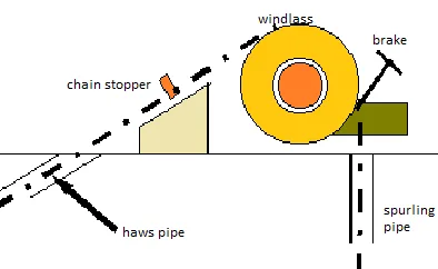
Spurling Pipe & Sleeve
- Vertical heavy steel conduit linking weather deck to chain locker
- Bell-mouthed ends at top and bottom prevent link chafing
- Arranged directly underneath the windlass gypsy cable lifter
- Canvas sleeve with lashing hoods deck opening against downflooding
Hawse Pipe & Wash
- Heavy cast-steel conduit connecting forecastle deck to outer shell
- Stows anchor shank snugly into recess during ocean voyages
- Integrated high-pressure sea wash ring powered by fire main
- Flushes sea mud, clay, and sand off chain before entering locker
Chain Stopper & Eductor
- Roller / guillotine stopper locks cable when riding at anchor
- Directs riding surges to deck hull structure, protecting windlass
- High-velocity eductor pump driven by fire main water
- Continuously evacuates bilge mud slurry straight overboard
3. The Bitter End: Securing the Anchor Cable
The bitter end is the end of the chain secured in the chain locker of a vessel, which is attached to the hull by a quick-release mechanism.
Securing Arrangement:
- The end of the cable is connected to the deck or bulkhead in the chain locker.
- Existing stiffeners are fitted to the fore side of the collision bulkhead; two similar sections are fitted horizontally back to back, riveted to the bulkhead and welded to the stiffeners.
- Stiffeners are fitted outside the locker to prevent damage from the chains.
- A space is allowed between the horizontal bars to allow the end link of the cable to slide in and be secured by a bolt.
- A centreline division is fitted to separate the two chains (port and starboard).
- If the locker is fitted in the forecastle, the bulkhead may be used to support the windlass.
In an emergency — such as the cable running away or the ship dragging toward a lee shore — the bitter end must be releasable quickly so the entire cable can be let go without endangering the vessel. The bolted arrangement allows the retaining pin to be drawn from outside the locker so no crew member needs to enter the space during a runaway surge.
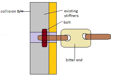
Bitter End Purpose
- The ultimate terminal link anchoring the cable to the vessel
- Secured to reinforced collision bulkhead stiffeners
- Never permanently welded to the hull or locker plating
- Allows instantaneous emergency slip to prevent hull rupture
Channel Bracket & Pin
- Two heavy horizontal steel channel bars mounted back-to-back
- End link slides securely into machined slot between bars
- Drop-in hardened steel pin secures the link under load
- Remote release wire led to weather deck for safe withdrawal
Structural Backing
- Bulkhead stiffeners fitted on fore face outside the locker
- External placement completely prevents cable impact damage
- Heavy doubler backing plates disperse concentrated shock loads
- Independent attachments provided for port and starboard cables
4. Access, Drainage & Windlass Support
- A hinged door is fitted in the forward bulkhead, giving access to the locker from the store space.
- The locker is fitted with a false floor to allow drainage of water and mud, with the help of a drain plug in the forward bulkhead.
- If the locker is fitted in the forecastle, the bulkhead may be used to support the windlass.
- Stiffeners are fitted outside the locker to prevent damage from the chains.
- Access and ventilation arrangements must allow safe entry for inspection, cleaning and maintenance of the cable and locker structure.
Anchor cable arrives covered in mud and water. Without a false floor and drain plug, this debris and water would collect at the bottom and accelerate corrosion of the cable and locker structure. The drainage system keeps the locker dry at the bottom.
Access & Enclosed Space
- Hinged watertight door in forward bulkhead opens from boatswain store
- Strict Enclosed Space Entry permit-to-work protocols apply
- Rusting steel cable and moist environment deplete oxygen rapidly
- Atmosphere check (O₂ ≥ 20.9%) and forced ventilation required prior to entry
Mud Sump & Drainage
- Perforated false floor keeps stowed cable dry above standing mud
- Bilge eductor continuously discharges washing water overboard
- Threaded bronze/steel drain plug in forward bulkhead
- Drain plug opened manually during drydocking to flush sediments
Windlass Support Piers
- Windlass experiences tremendous breaking pull and anchor riding shocks
- Forecastle deck reinforced locally with thick insert plates
- Chain locker bulkhead and heavy tubular pillars act as direct piers
- Transmits vertical and overturning forces straight down to keel floor structure