Coaming scantlings, compression bar gaskets, resting pads, single pull / folding configurations, and surveyor ultrasonic testing.
8 min read
Intermediate
Ship Construction & Naval Architecture
Key Principles at a Glance6 points
Hatch covers maintain the ship weathertight integrity in all sea states, preventing green water on deck from flooding cargo holds.
Under International Load Line Rules, weather deck hatch coamings must be at least 600 mm in height in Position 1 (forward 0.25L) and 450 mm in Position 2, commonly built to 800 mm to provide personnel safety railing.
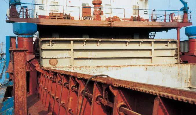
Coaming plates are at least 11 mm thick, reinforced with a continuous upper bulb angle stiffener and triangular coaming stays spaced no more than 3.0 m apart anchored to deck beams below.
Weathertight sealing relies on a knife-edge compression bar on the coaming indenting 8–12 mm into an extruded neoprene/rubber gasket housed in the cover retaining channel.
Resting pads (steel-on-steel bearing blocks) transfer the entire weight of the hatch cover and cargo to the coaming, preventing permanent crushed deformation of the rubber gasket.
Classification societies mandate annual weathertight verification using Ultrasonic Testing (Class-approved, works in freezing weather with full cargo), High-Pressure Hose Testing (2.0 bar at ≤ 1.5 m), or compression Chalk Testing.
1. Hatch Coaming Structural Design & Load Line Rules
Idea in one line: the coaming is a raised steel wall that turns a hole in the deck back into strength — height is the law, stays are the muscle.
A cargo hold hatch coaming is a heavy vertical steel boundary welded continuously around each deck opening. It serves three vital functions:
Hydrodynamic Barrier: Elevates the hatch opening above the weather deck to prevent green seas, wave wash, and rainwater from entering cargo spaces.
Structural Deck Reinforcement: Compensates for the massive loss of deck plate sectional area where large cargo openings are cut out, forming deep longitudinal and transverse strength girders.
Hatch Cover Foundation: Provides a rigid, level bearing surface fitted with rails, compression bars, resting pads, and cleating brackets to support and seal the hatch covers.
International Load Line Convention (ILLC) Dimensions
Position 1 (Exposed freeboard deck forward 0.25L and raised quarter decks): Minimum coaming height is 600 mm. In modern ship construction, it is standard practice to extend this to 800 mm to simultaneously satisfy statutory personnel fall-protection railing requirements.
Position 2 (Exposed superstructure decks aft of 0.25L): Minimum coaming height is 450 mm.
Scantlings & Stiffening: Coaming plates must be a minimum of 11 mm thick. Where coaming height reaches or exceeds 600 mm, a heavy horizontal bulb angle or flanged plate stiffener is welded along the upper perimeter, supported by triangular vertical stays spaced no more than 3.0 meters apart, aligned with transverse deck beams below.
Orbit the closed hatch and select any part to isolate it. Use the mode buttons and the Play control in the viewer to run the opening cycle: the cleats release, the cover lifts clear of the compression bar, gasket and resting pads, the hydraulic cylinders push the end-hinge arms, and each pair folds before lowering and securing again.
Loading interactive 3D hatch cover model…
Figure 1: Hatch coaming structural arrangement under ILLC rules. Showing required coaming heights (600 mm Position 1 / 450 mm Position 2), triangular stays spaced ≤ 3.0 m apart anchored to underdeck transverse beams, upper continuous bulb rail stiffener, and drainage channel.
Idea in one line: steel pads carry the weight so rubber only seals — knife edge bites the gasket, cleats hold it, pads stop the crush.
A fundamental rule in naval architecture distinguishes between watertight and weathertight boundaries:
Watertight (Bulkheads & Hull): Capable of withstanding a continuous hydrostatic head of water from either side without any leakage.
Weathertight (Hatch Covers & Superstructure Doors): Water will not penetrate into the ship interior under any dynamic wave action or sea condition (green seas, rain, heavy spray), but the structure is not designed for total permanent submerged head pressure.
The Triad of Weathertight Integrity:
1
The Knife-Edge Compression Bar: A solid, continuous steel or stainless steel flat bar welded vertically to the top of the coaming. It must be perfectly straight, smooth, and free of rust scale or pitting.
2
Extruded Neoprene/Sponge Gasket: Housed inside a steel retaining channel along the bottom perimeter skirt of the hatch cover. Under cleat tension, the compression bar indents 8 to 12 mm into the rubber, creating a continuous airtight, water-excluding pressure barrier.
3
Steel Resting Pads (Bearing Blocks): Machined steel blocks positioned at intervals between the cover skirt and the coaming top plate. Critical Rule: The rubber gasket must never carry the physical weight of the hatch cover or any cargo loaded on top! Once the cover is lowered and cleats are tightened, the resting pads make steel-to-steel contact, precisely locking the compression at its designated 8–12 mm limit and preventing the rubber from being permanently flattened or crushed.
4
Quick-Acting Cleats: Lever-cam devices fitted with resilient rubber/Belleville spring washers. They clamp the cover tightly against the resting pads while allowing elastic movement during hull flexing in rough seas.
Figure 2: Weathertight sealing triad. Left: Knife-edge compression bar indents 8–12 mm into neoprene gasket while machined steel resting pads make direct steel-to-steel contact to absorb cargo/cover loads. Right: Quick-acting cleat featuring resilient Belleville spring washer pack allowing elastic hull flexing.
3. Hatch Cover Types: Single Pull, Folding & Side-Rolling
Idea in one line: every cover is a trade between opening speed, deck space and machinery — fold it, pull it, roll it or lift it off.
Hatch covers are categorized by their kinematic opening mechanism, which is chosen based on ship type, hold dimensions, available deck space, and cargo handling gear:
1. Folding Hatch Covers (Hydraulic): The standard on multi-purpose general cargo ships and modern handysize bulk carriers. Panels are hinged together in pairs and actuated by hydraulic cylinders mounted externally on the coaming or internally within the panels. As the cylinders extend, the panels fold upward vertically into a compact accordion stowage block at the hatch end, clearing the entire cargo opening.
2. Single Pull Covers (MacGregor Wire/Chain Drive): The classic mechanical system. Panels are connected in series by balancing chains and ride along coaming rails on eccentric balancing wheels. When pulled by a continuous wire winch or motor chain, the panels roll horizontally toward the stowage rack. At the end of travel, the wheels drop into curved guides, causing each panel to tip into a vertical position, stowed compactly like books on a shelf.
3. Side-Rolling Hatch Covers: The industry standard for large Capesize bulk carriers and Very Large Ore Carriers (VLOCs). Because huge hatches would create massive, dangerously tall vertical sails if folded, side-rolling panels are used instead. Hydraulic jacks lift the cover vertically off its compression bar seal ("wheel jack-up"), and the panels then roll athwartships outboard to port and starboard on heavy wheels driven by high-torque rack-and-pinion or chain drives.
4. Lift-Away Pontoon Covers: Used almost exclusively on container ships. Pontoons have no on-board mechanical or hydraulic linkages. Instead, shore container gantry cranes hook into lifting sockets, lift each pontoon completely off the ship, and stack them temporarily on the pier or adjacent hatch blocks during container loading.
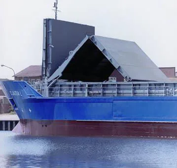
Figure 3: Kinematic comparison of commercial hatch cover mechanisms. 1: Hydraulic folding covers (hinged panel pairs accordion upward at hatch ends). 2: Mechanical single-pull MacGregor system (wire winch pulls panels which drop into vertical stowage racks). 3: Side-rolling covers (hydraulic jack-up wheels roll athwartships outboard for giant Capesize/VLOC holds).Photo: Folding hatch cover with hinged panel pairs folding vertically into a stowage block at the hatch end.
Photo: Hatch cover stowed clear of the opening, showing the unobstructed cargo hold access.
Idea in one line: prove the seal before the sea does — ultrasound hears the leak, the hose shows it, chalk maps where the gasket misses.
Water ingress into cargo holds accounts for millions of dollars in cargo claims and has caused bulk carrier sinkings through cargo liquefaction and progressive flooding. Classification surveyors and ship officers use three established testing procedures to certify hatch cover weathertightness:
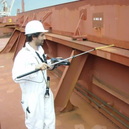
An ultrasonic multi-transmitter is placed inside the closed cargo hold. It emits omnidirectional ultrasound waves in a specific high-frequency band (typically 40 kHz). The surveyor, wearing noise-cancelling headphones connected to a handheld digital receiver, walks along all external coaming joints and cross-panel seams. Sound escaping through low-compression spots or damaged gaskets is converted into audible signals and precise decibel (dB) readings.
Open Hatch Value (OHV): Baseline sound level measured with the hatch cover slightly ajar.
Acceptance Standard: Sealing is considered weathertight if readings along the seams do not exceed 10% of OHV. Any reading > 10% indicates compression failure.
Key Advantages: Non-destructive, can be performed with cargo already loaded in the hold, works in sub-zero freezing weather, and generates digital downloadable records for insurance and P&I clubs.
2. High-Pressure Hose Water Testing:
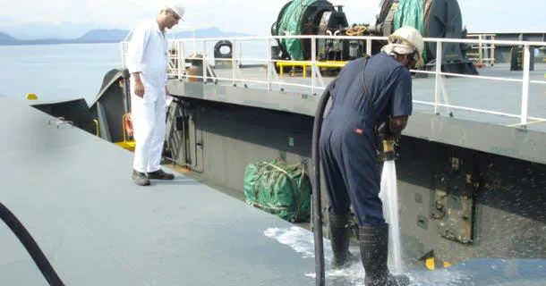
A physical water jet from a fire hose fitted with a minimum 12 mm (1/2 inch) nozzle is sprayed directly at every gasket seam and cross-joint from a distance of 1.0 to 1.5 meters, at a minimum pressure of 2.0 bar (200 kPa / 0.5 m/s jet). An inspector stationed inside the dark hold checks for drips, runs, or water ingress.
Drawbacks: Requires an empty hold, cannot be performed in sub-zero freezing climates (ice formation damages rubber), and requires two crew members.
3. Chalk Compression Testing:
The oldest qualitative workshop test. White chalk is applied liberally along the top knife-edge of the entire steel compression bar. The hatch cover is closed and fully cleated to operational values, then opened. The rubber gasket is examined: a continuous white chalk stripe along the center of the rubber proves unbroken contact, whereas any blank gaps indicate insufficient compression, worn rubber, or warped coamings.
Limitation: Tests contact alignment only; does not prove actual weathertightness under dynamic sea water pressure.
Figure 4: Weathertightness survey testing procedures. Left: Ultrasonic testing using an internal 40 kHz omnidirectional transmitter and handheld receiver (sealing is sound if leakage is ≤ 10% OHV; works with cargo loaded). Top right: Water hose testing (minimum 2.0 bar pressure at 1.0–1.5 m with a 12 mm nozzle on empty hold). Bottom right: Chalk compression imprint revealing contact gaps.Photo: Hose testing of hatch cover seams with a high-pressure water jet directed at the gasket joints.
Photo: Ultrasonic weathertightness testing with the receiver walked along external coaming joints and cross-panel seams.
5. Dye Penetrant Testing for Cracks
Idea in one line: dye finds the cracks your eyes cannot — clean it, bleed it red, and let white developer draw the verdict.
The dye penetrant test is the most common test method used to detect cracks in components on board ship — including hatch coaming plating, weld seams and structural fittings.
Principle:
The penetrant is the same penetrating oil used to loosen a rusted nut and bolt, except that it contains a dye which finds its way into the smallest of cracks — even those invisible to the naked eye.
Some dyes are fluorescent, used in conjunction with an ultraviolet light, which makes the cracks glow green when ordinary lighting is reduced.
Others use a developer which makes the dye stand out as a red line.
How It Is Done:
This type usually comes in three aerosols — cleaner, dye, developer:
1
Clean. Spray cleaner on, strip oil, rust and paint, then let the component dry fully so capillaries stand open.
2
Dye. Spray penetrating dye on and wait 5 minutes while capillary action drags it into the smallest cracks.
3
Wipe. Wipe the excess coating off the surface — dye stays trapped inside the crack, nowhere else.
4
Develop. Spray developer on; it draws the trapped dye back out by reverse capillary action and highlights any crack present as a red line — or a green glow under ultraviolet light with fluorescent dye.
Figure 5: 4-stage dye penetrant inspection procedure. 1: Surface pre-cleaning and degreasing. 2: Penetrant red dye application (5–10 min capillary dwell). 3: Careful wiping of excess surface dye. 4: White chalk developer application drawing trapped red dye out of the crack to produce an unmistakable red indication line.
Where It Is Used
Dye penetrant testing is a surface method — it reveals surface-breaking cracks only, not internal defects. It is widely used on hatch coamings, weld toes, deck fittings and machinery components where cracking is suspected.