
Bow Thrusters: Construction, Drive Types & Operation
The transverse tunnel that pushes the bow sideways — how it is built, driven and protected from cavitation.
Key Principles at a Glance 6 points
- Many ships are fitted with bow thrust units to improve manoeuvrability; they are an obvious feature in ships working within, or constantly in and out of, harbour, where close control is obtained without tugs.
- They have also proved of considerable benefit to larger vessels such as oil tankers and bulk carriers, where the tug requirement has been reduced.
- In all cases, penetrating the hull forward causes an increase in ship resistance and hence fuel cost, although the increase is small.
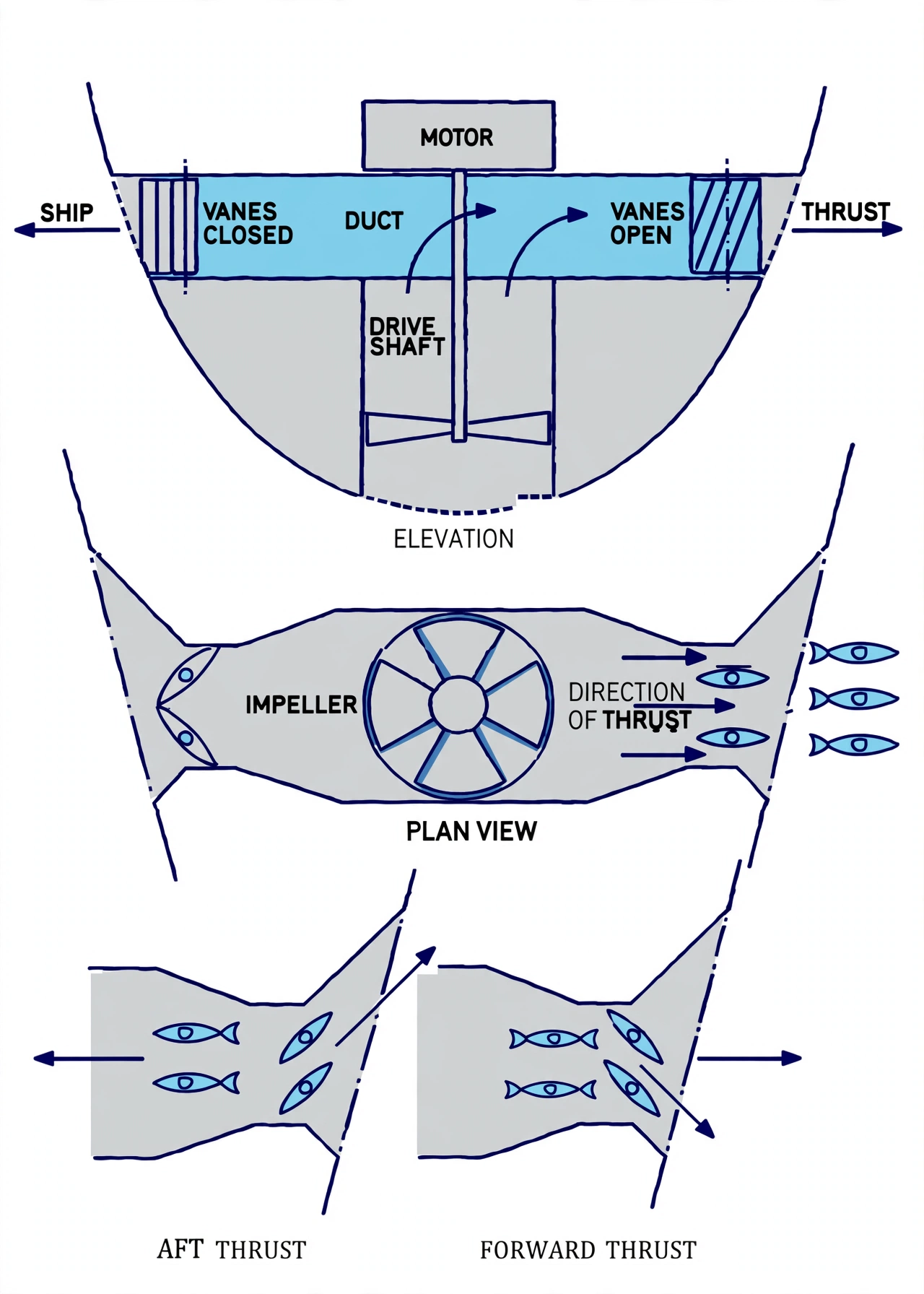
- A popular arrangement is a cylindrical duct passing through the ship from side to side, fitted with an impeller which can produce thrust to port or starboard.
- The complete duct must lie below the waterline at all draughts, the impeller acting best when subject to a reasonable head of water, thus reducing cavitation.
- The impeller may be fixed pitch with a variable-speed reversible motor or reverse gearing, or controllable pitch with a constant-speed drive; power may be from an electric motor, a diesel engine or a hydraulic motor.
1. Function & Benefits of a Bow Thruster
- Many ships are fitted with bow thrust units to improve their manoeuvrability.
- They are an obvious feature in ships working within, or constantly in and out of, harbour, where close control is obtained without the use of tugs.
- They have also proved of considerable benefit to larger vessels such as oil tankers and bulk carriers, where the tug requirement has been reduced.
The bow is the point furthest from the pivot of a ship moving ahead and is the hardest place to control in tight quarters. A bow thruster gives a direct transverse force right where it is most needed, allowing berthing and unberthing without tugs.
Orbit the bow and select any part to isolate it. Switch modes across harbour function, tunnel & impeller, drive & power and head & cavitation. Use Full Screen to study the model.
2. Construction: Transverse Tunnel & Impeller
- In all cases, the necessity to penetrate the hull forward causes an increase in ship resistance and hence in fuel costs, although the increase is small.
- A popular arrangement is to have a cylindrical duct passing through the ship from side to side, in which is fitted an impeller which can produce a thrust to port or starboard.
- The complete duct must lie below the waterline at all draughts.
- The impeller acts best when subject to a reasonable head of water, thus reducing the possibility of cavitation.
- The tunnel ends are faired into the hull shell, and the duct edges are strengthened to resist the concentrated forces.
If the impeller runs too close to the surface or is overloaded, the pressure on the blades drops and water vapour bubbles form — cavitation. Keeping the duct well submerged provides a positive head that suppresses cavitation and protects the impeller from erosion.
3. Drive & Power Options
Impeller Drive:
- The impeller may be of fixed pitch with a variable-speed motor which is reversible or has reverse gearing.
- Alternatively a controllable pitch impeller may be used, having a constant-speed drive.
Power Source:
- Power may be provided by an electric motor.
- A diesel engine.
- Or a hydraulic motor.
4. Operation, Efficiency & Precautions
Operating Principles:
- The thruster is most effective at low ship speed, when it is used for berthing and close-quarters manoeuvring.
- Thrust falls off as ship speed rises, because the transverse duct flow is disturbed by the forward motion.
- The impeller must be kept well submerged; at light draught (ballast) the duct may come close to the surface and cavitation increases.
Precautions:
- Avoid running the thruster at high speed when the bow is pitching heavily, to prevent cavitation and impeller damage.
- Watch for excessive current draw or tripping — a sign of fouling in the tunnel or cavitation.
- The tunnel intake and outlet grids must be kept clear of obstructions and protected against damage.
- Regular inspection of the tunnel coating and impeller blade condition is required; cavitation erosion and corrosion reduce performance.
Surveyors commonly ask: "Explain the bow thruster." Answer with function (harbour manoeuvrability without tugs), construction (transverse submerged tunnel + impeller, small resistance penalty), and drive/power (fixed pitch variable-speed reversible, or controllable pitch constant speed; electric/diesel/hydraulic).