How a submerged underwater bulb generates a counter-wave to cancel bow waves, slash hull drag, and save tons of fuel.
6 min read
Intermediate
Ship Construction & Naval Architecture
Key Principles at a Glance7 points
A ship pushing through water generates two primary forms of resistance: Frictional skin drag and Wave-making (residuary) resistance.
At service speeds (Froude numbers 0.2 to 0.3), wave-making resistance can account for up to 50% of the total engine power required.
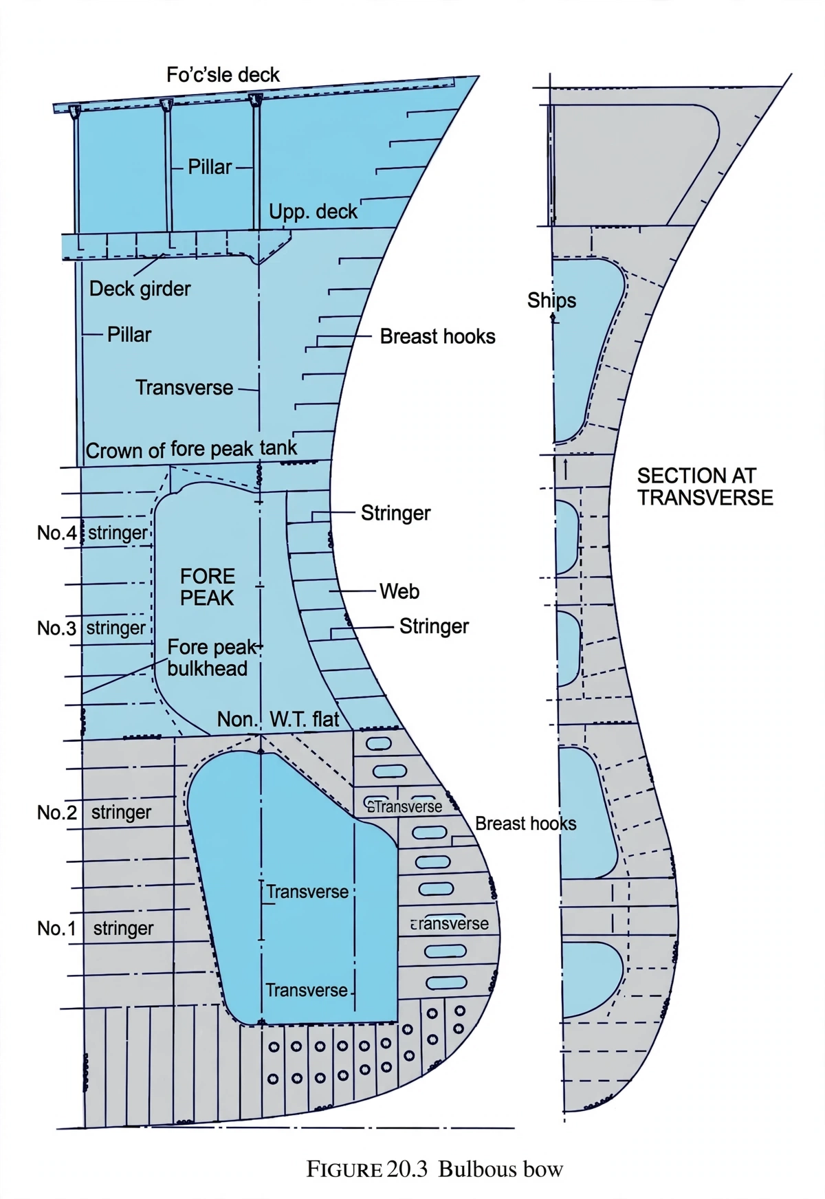
The bulbous bow is located just below the water line, protruding forward at the stem/forefoot.
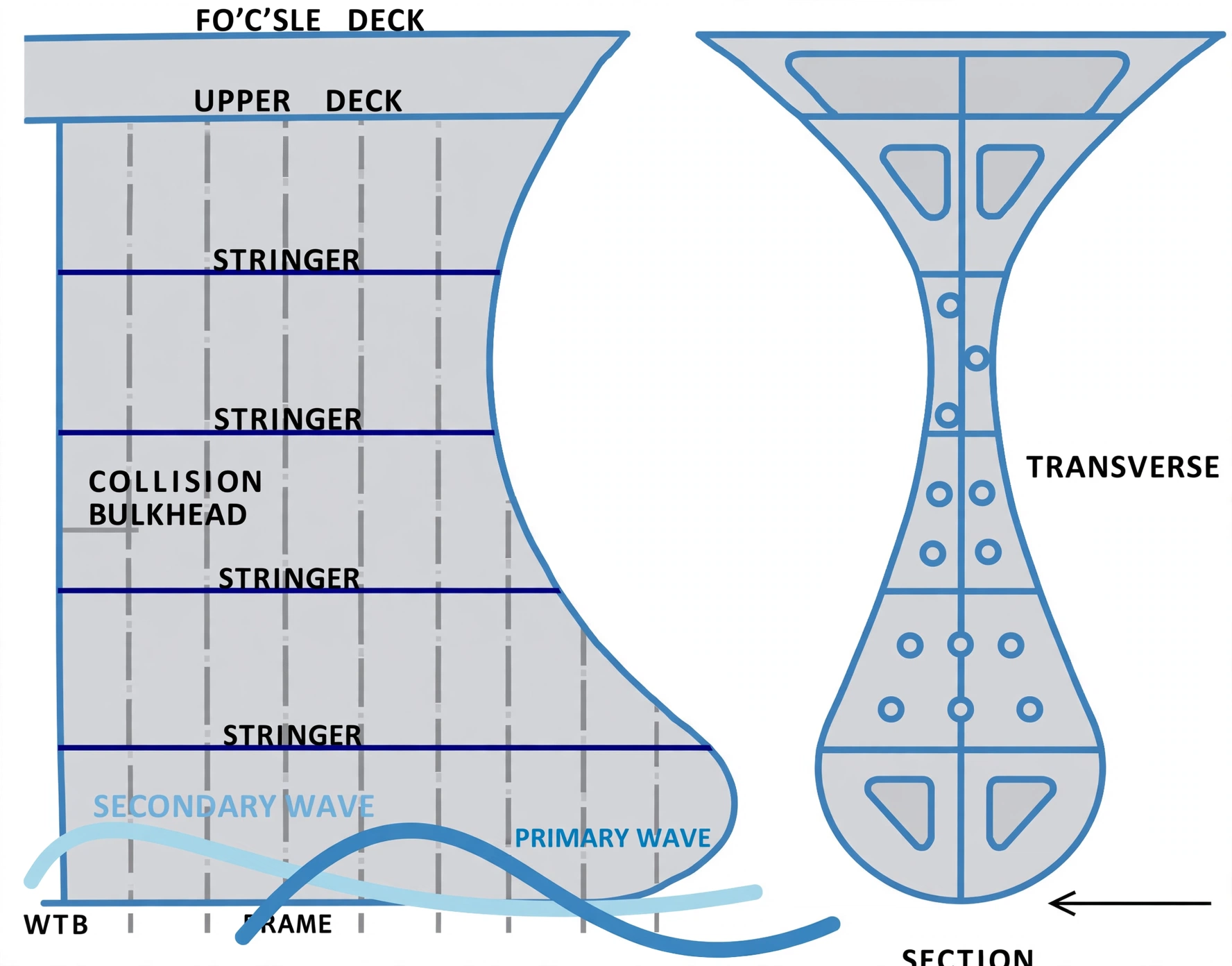
Physics of Wave Cancellation: The bulb creates its own primary wave with a trough that coincides with the crest of the main hull bow wave.
Destructive interference between the two out-of-phase waves largely flattens the resulting wave system, reducing wave-making drag by 10%–15%.
Secondary benefits include reduced pitching motions in head seas, increased reserve buoyancy forward, and higher sustained voyage speeds.
Limitations: Bulbs are tuned to specific design speeds and drafts. At slow steaming or non-optimal ballast drafts, a bulb can create slight additional frictional drag.
1. Why Ships Make Waves: The Battle Against Residuary Resistance
When a large commercial vessel (container ship, bulk carrier, or tanker) sails across the ocean, the water resists its motion through two fundamental mechanisms:
Frictional Resistance (Skin Friction)
Caused by viscous shear stress between the outer steel hull plating and the water molecules. Governed by wetted surface area, hull roughness, and marine bio-fouling.
Wave-Making Resistance (Residuary Drag)
As the bow parts the water, it creates a high-pressure zone that piles up a towering bow wave. The kinetic energy radiated away into those ocean waves represents pure lost engine fuel.
At high service speeds, wave-making resistance escalates exponentially. Without hydrodynamic intervention, ships would waste immense amounts of fuel simply churning up waves.
Figure 1: Components of Ship Resistance. A conventional bare stem pushing through calm water creates a high-pressure stagnation zone (+P) that generates towering bow waves. The radiated wave energy represents wave-making resistance, which consumes up to 50% of total engine propulsion at full service speeds.
2. The Wave Cancellation Principle: Out-of-Phase Interference
The bulbous bow is a carefully engineered hydrodynamic protrusion placed at the vessel's stem, situated just below the laden waterline.
Its brilliance lies in classical wave mechanics: Destructive Interference.
1
Primary Wave (Bulb Wave W₁): As the submerged bulb punches through the sea ahead of the ship, water accelerates over its curved crown, creating a localized pressure drop. This generates an immediate wave system with a wave trough directly behind the bulb tip.
2
Secondary Wave (Main Hull Wave W₂): A few meters aft, the broad shoulders of the ship's main hull arrive and compress the water, attempting to form a massive wave crest.
3
Destructive Cancellation: Because the bulb was placed precisely forward of the main stem, the bulb's wave trough aligns with the main hull's wave crest. The trough and crest cancel each other out!
4
Calm Resultant Flow: The towering bow wave is flattened into a smooth, streamlined wake, cutting wave resistance by 10% to 15%.
Figure 2: Destructive Wave Interference Principle. The submerged bulb creates a localized pressure trough (-A) positioned directly beneath the main hull's natural bow wave crest (+A). When the two out-of-phase wave systems collide, they undergo destructive interference, neutralizing the bow wave into a flattened, low-drag resultant flow.
Figure: Bulbous bow — submerged bulb at the forefoot generating a counter-wave to cancel the main bow wave and cut wave-making resistance.
3. Advantages vs. Operational Trade-Offs
While a bulbous bow provides monumental fuel savings, it is not a magic wand for every vessel. Modern naval architects design bulbs tailored to specific voyage profiles:
Figure 3: Operating Conditions: Laden Design Speed vs. Slow Steaming / Ballast Draft. The bulbous bow is tuned to a vessel's design speed and fully laden draft (left), maximizing wave cancellation. At slow steaming speeds or light ballast drafts (right), wave-making resistance is naturally low, and the bulb generates minor frictional penalties due to added wetted surface area.
Operating Condition
Bulb Performance
Engineering Explanation
Design Service Speed (16–24 kts)
Maximum Efficiency (−12% to −15% Fuel)
Wave wavelengths match the bulb geometry perfectly; complete destructive wave cancellation occurs.
Slow Steaming (8–12 kts)
Neutral or Slight Penalty (+1% to +3% Drag)
At slow speeds, wave-making is negligible. The bulb merely adds extra wetted surface area, increasing skin friction.
Fully Laden Draft
Optimally Submerged
Bulb is submerged at its exact designed depth below the waterline to guide hydrodynamic streamlines.
Extreme Light Ballast Draft
Reduced Benefit / Slamming Risk
If the bulb breaks the surface, it ceases to generate a subterranean pressure trough and can be subject to wave slamming.
Beyond slashing fuel burn, the bulbous bow delivers two crucial secondary benefits for seamanship:
Pitching Damping: The large submerged volume of the bulb acts as a hydrodynamic damper, resisting rapid vertical bow motions when meeting head seas and improving crew comfort.
Better Hull Wake Field: By smoothing the flow around the shoulders of the ship, the bulb helps deliver a more uniform wake field into the propeller aft, boosting overall propulsive efficiency.
Figure 4: Secondary Seamanship Advantages: Pitch Damping & Propeller Wake Uniformity. The massive submerged volume of the bulb produces restorative hydrodynamic damping forces against head sea swells (left), reducing pitch motions by up to 30%. Furthermore, guiding streamlines smoothly along the hull (right) delivers a cleaner, non-turbulent wake field into the propeller aft.
Figure: Forepeak sections in waves — bulb volume damping pitch and smoothing inflow to the propeller.