
Double Bottom Construction & Deep Tanks
Transverse vs. longitudinal framing, solid plate vs. bracket floors, tank margin plates, and deep tank hydrostatic head testing.
Key Principles at a Glance 6 points
- The double bottom structure provides structural grounding protection, immense longitudinal hull girder bending strength, and storage for fuel, ballast, and fresh water.
- A continuous watertight Center Girder runs along the keel, taking concentrated drydocking keel-block forces; intercostal side girders are fitted port and starboard based on ship breadth (1 for B > 10m, 2 for B > 20m).
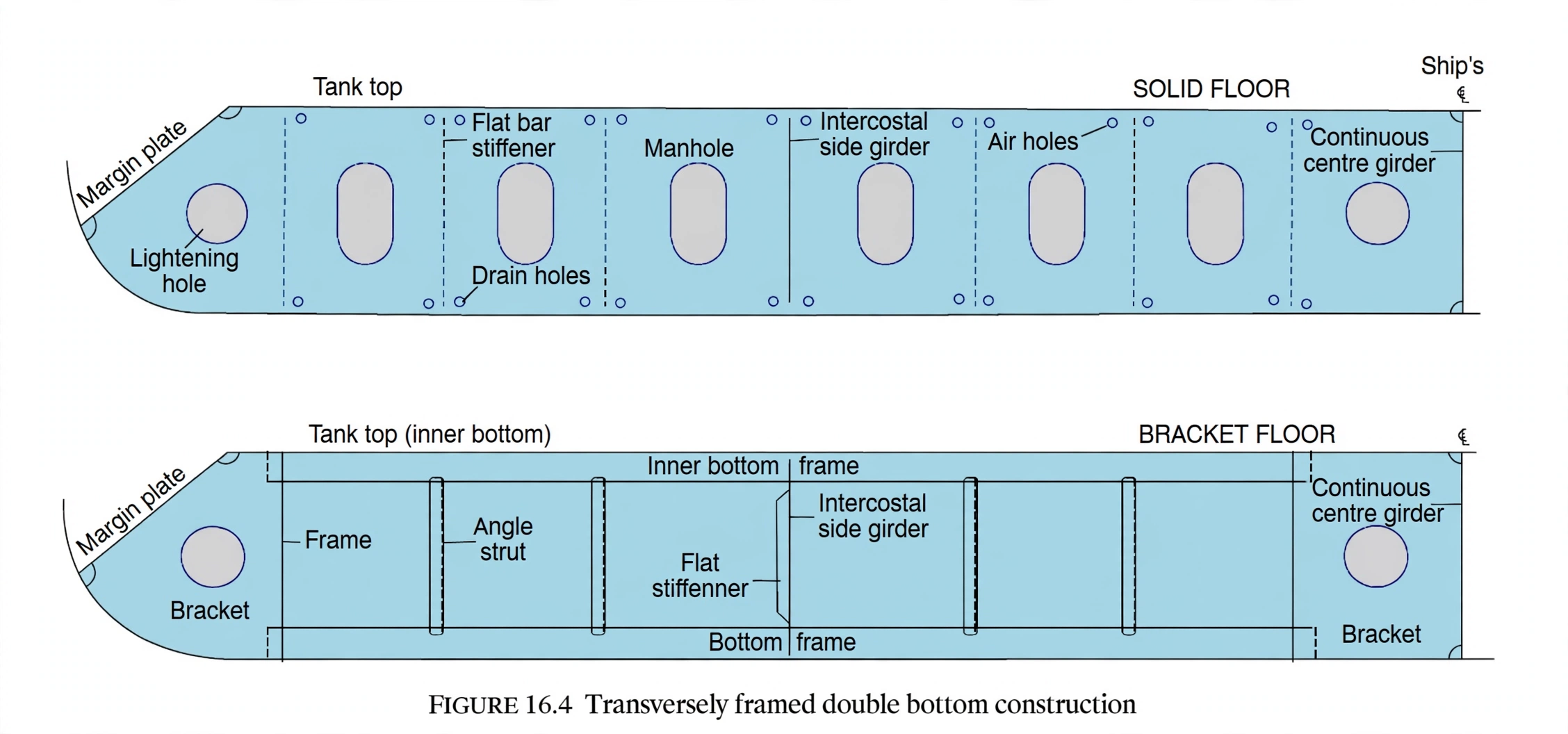
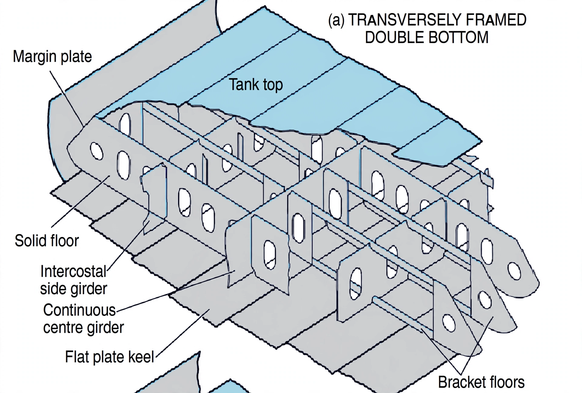
- Transversely framed double bottoms use solid plate floors fitted at every frame in the engine room and pounding region (and every 3.0 m elsewhere), with intermediate frames supported by open bracket floors.
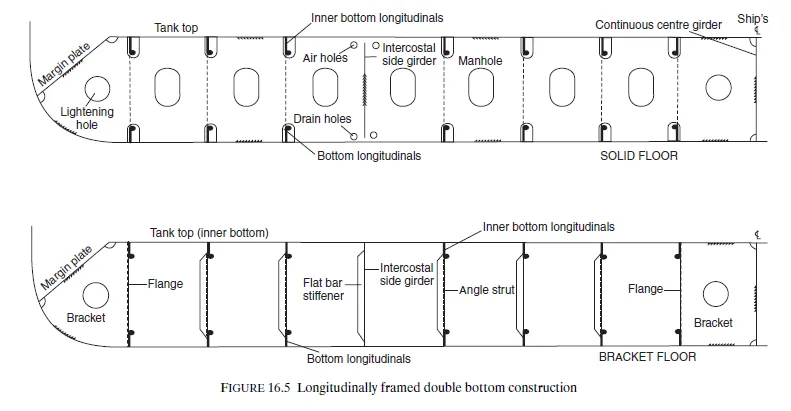
- Solid floors incorporate lightening holes for human access, limber holes at the bottom for drainage to bilge wells, and air holes at the top to prevent trapped air pockets.
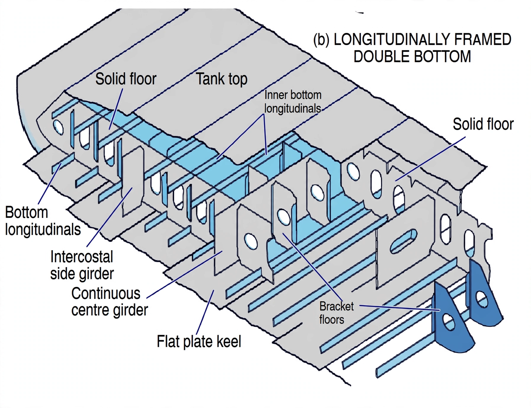
- Modern large vessels (> 120m) adopt longitudinal double bottom framing, running continuous bottom and tank top longitudinals through widely spaced solid floors (up to 3.8m) to resist global hogging and sagging.
- Deep tanks extend from the inner bottom up to the lowest deck, fitted with centerline wash bulkheads to suppress Free Surface Effect, and must be tested to the top of the overflow pipe or 2.45m above the tank top, whichever is higher.
1. Double Bottom Structural Architecture & Longitudinal Girders
The Double Bottom (DB) is the foundational structural sandwich of the modern steel merchant ship, bounded on the bottom by the outer bottom shell plating and on the top by the inner bottom (tank top) plating. It serves three indispensable maritime purposes:
- Grounding Survivability: If the outer hull plating is torn open during a bottom grounding or underwater collision, the watertight inner bottom prevents water from entering cargo holds or machinery spaces.
- Hull Girder Bending Resistance: Forms the primary lower flange of the ship structural "box girder," carrying immense tensile stresses in sagging and compressive stresses in hogging.
- Subdivided Fluid Storage: Accommodates heavy ballast water, heavy fuel oil (HFO), marine diesel oil (MDO), lube oil, and fresh water, maintaining vessel trim and lowering the ship center of gravity ($G$).
- Continuous Center Girder: A heavy, unbroken longitudinal plate running along the centerline from the collision bulkhead to the aft peak bulkhead. It is fully watertight/oiltight between tanks and transmits massive point loads directly into drydock keel blocks during docking.
- Intercostal Side Girders: Longitudinal plates fitted between transverse floors. Classification societies mandate:
- One side girder port and starboard where vessel breadth $B > 10\text{ m}$ (up to $20\text{ m}$).
- Two side girders port and starboard where vessel breadth $B > 20\text{ m}$.
- Additional side girders are installed under main engine bedplates, thrust bearings, boiler seatings, and throughout the forward pounding region ($0.05L$ to $0.25L$).
- Tank Margin Plate: The outboard boundary of the double bottom, which turns downward at an angle or meets the outer hull shell squarely, creating the lower margin bilge well where hold drainage collects.
Orbit the midship section, pick any part to isolate it, then switch modes to compare solid plate floors and bracket floors, examine longitudinal framing, and watch the deep tank fill to its 2.45 m test head.
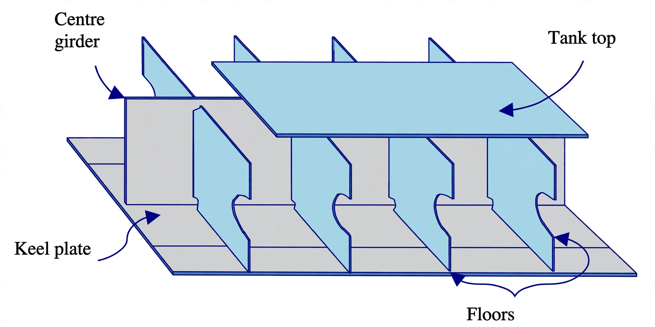
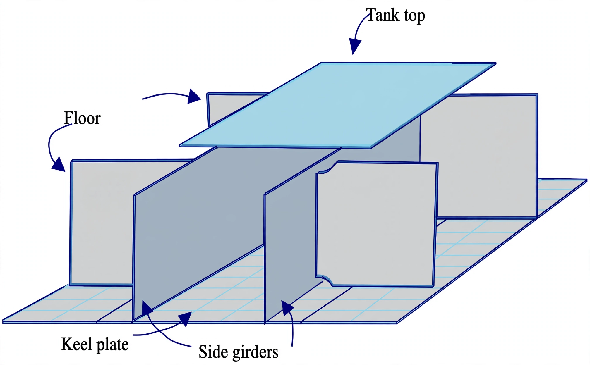
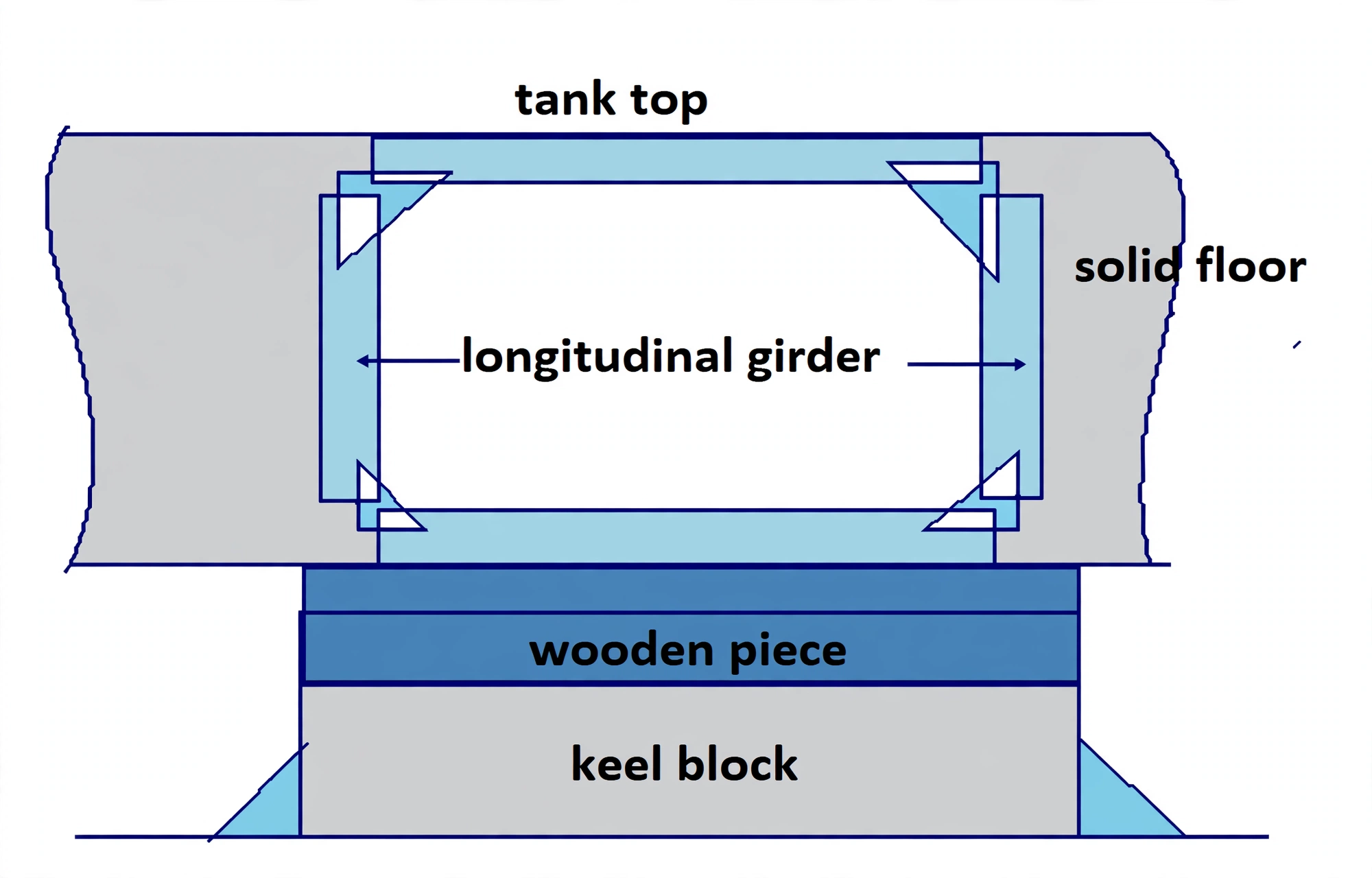
2. Transverse Framing: Solid Plate Floors vs. Bracket (Open) Floors
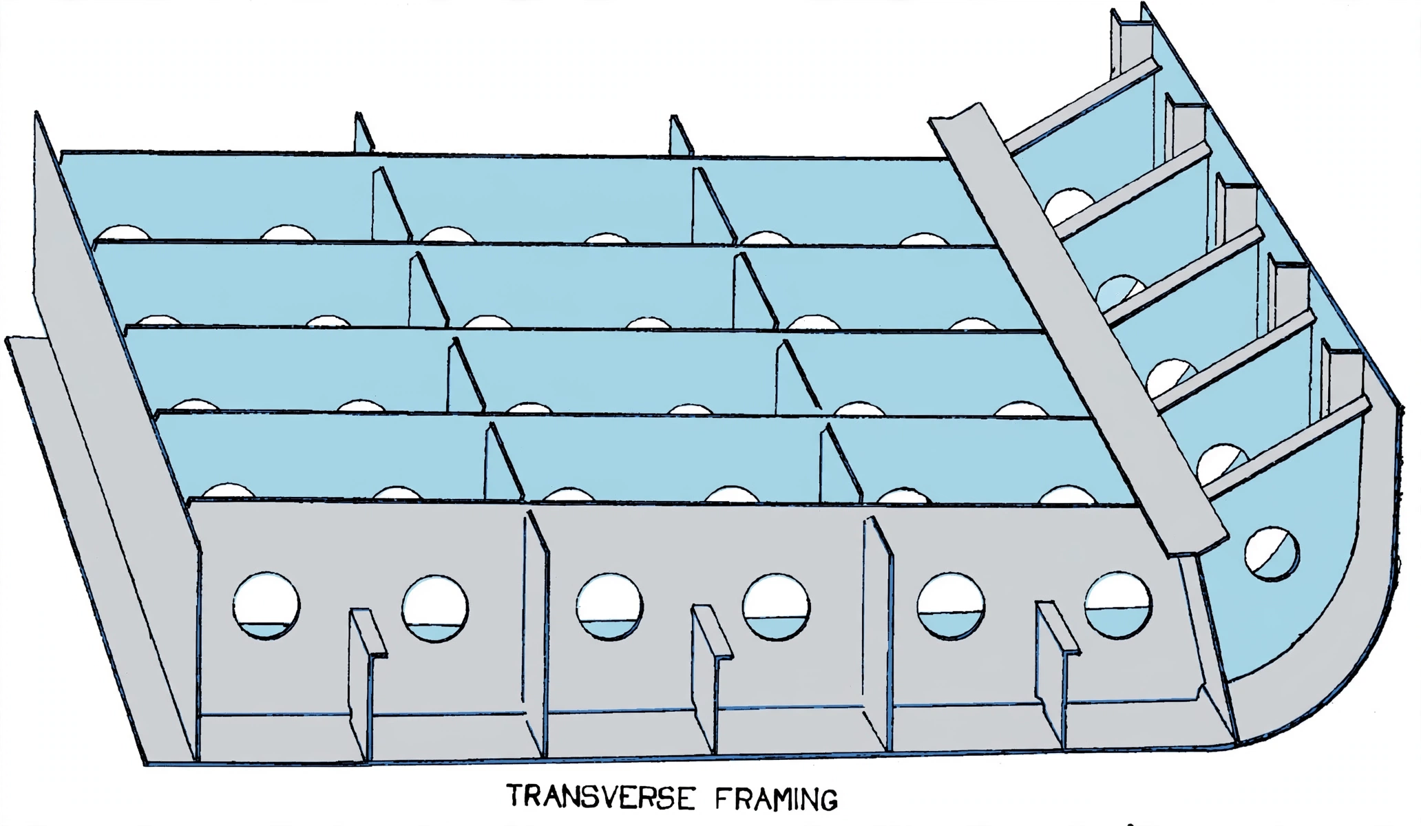
In a transversely framed double bottom, transverse vertical diaphragms known as floors provide the primary support spanning athwartships between the center girder and the outer hull sides.
Solid Plate Floors:
Solid plate floors consist of continuous vertical steel plates welded between the inner and outer bottom shells. They are heavily reinforced with vertical stiffeners and are strictly mandatory at:
- Every frame space in the machinery space (engine room): To withstand massive dynamic engine vibration and alternating torque loads.
- Every frame space in the forward pounding region ($0.05L$ to $0.25L$): To resist bottom slamming pressures during heavy pitching.
- Directly beneath boiler seatings, transverse bulkheads, and deep tank boundary bulkheads.
- Every frame on ships regularly discharged by heavy grab buckets.
- Everywhere else: Solid floors may be spaced up to 3.0 meters apart, with open bracket floors fitted at intermediate frames.
A solid floor must never be a blind plate (unless forming a watertight tank boundary). It requires three essential cutouts:
- Lightening Holes (Manholes): Large elliptical openings cut in the neutral axis of the floor to drastically cut hull deadweight while permitting surveyor and crew access for tank inspection. (Strictly prohibited directly under engine bedplates and thrust blocks).
- Limber Holes (Drain Holes): Small semicircular cuts located at the very bottom corners against the center girder and margin plate, enabling liquids to drain unimpeded to the bilge suction strums.
- Air Holes: Small semicircular cuts located at the very top edge flush with the tank top plating, allowing air and vapor to escape freely toward air pipes during tank filling, preventing catastrophic air pockets.
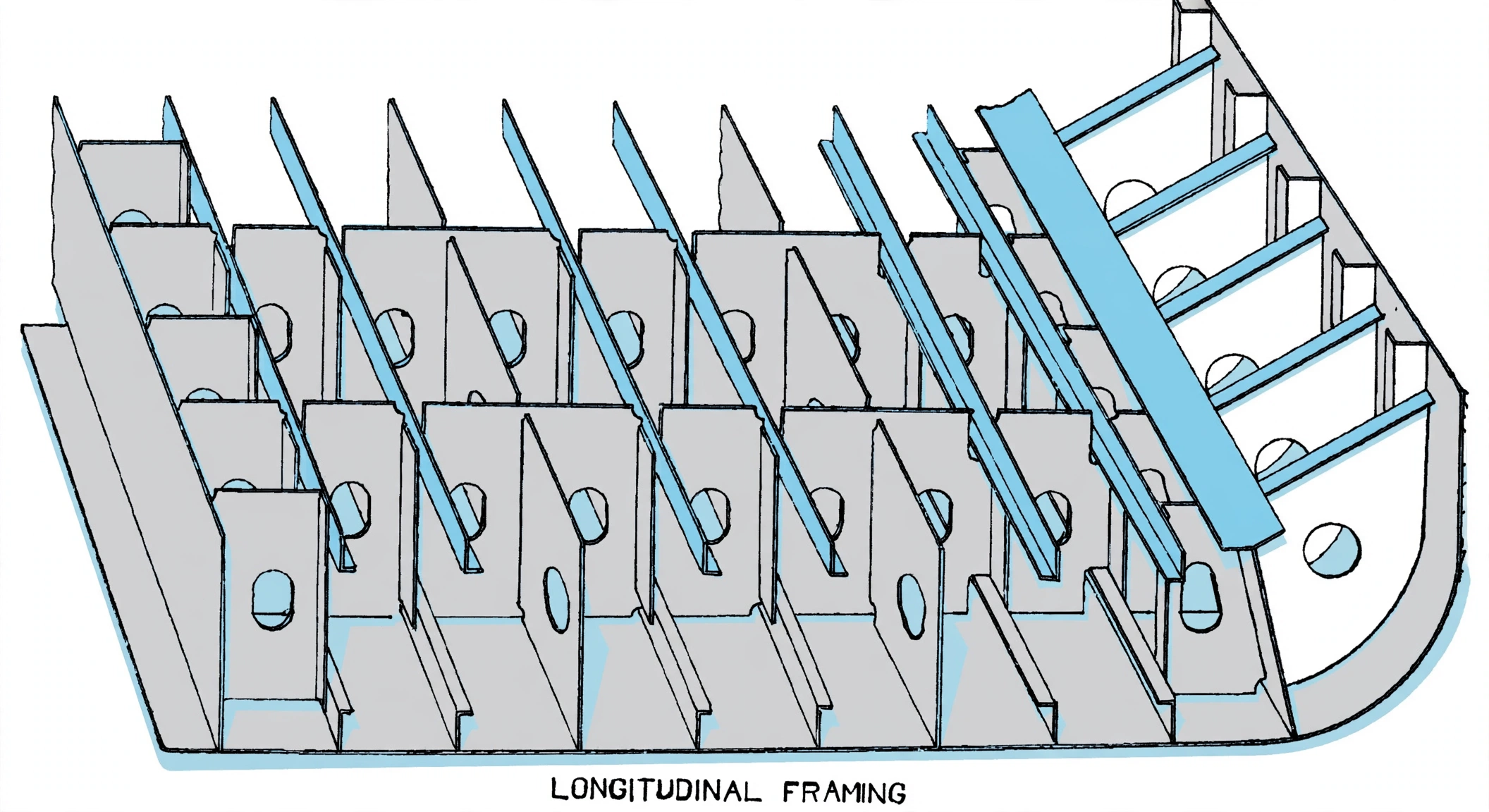
3. Longitudinally Framed Double Bottom Construction
While transverse framing is common on shorter vessels and localized high-stress zones, longitudinal framing is the standard for modern cargo vessels exceeding 120 meters in length.
Why Longitudinal Framing Dominates Large Vessels:
When a ship encounters large ocean waves, the entire hull acts as a continuous beam subjected to global bending: hogging places the deck in tension and the double bottom in compression, while sagging places the double bottom in tension. Longitudinal stiffeners (bulb flats or inverted angles) running continuously along the bottom shell and tank top:
- Directly resist global tensile and compressive stresses along the hull axis.
- Greatly enhance the buckling resistance of the bottom shell plating under high compressive loads.
- Save considerable structural steel weight compared to transverse floors.
Structural Arrangement of Longitudinally Framed Double Bottoms:
- Longitudinal Stiffeners: Spaced between 600 mm and 900 mm apart along both the outer bottom shell and the inner bottom tank top plating.
- Solid Plate Floors: Spaced much farther apart than in transverse systems, with typical spacing up to 3.8 meters (in the pounding region they are fitted on alternate frames, and at every frame space under the main engine).
- Slotting & Lugs: Where continuous longitudinals pass through the transverse solid floors, slots are cut into the floor plate, often backed by welded connecting lugs or flat collar plates to maintain water/oil tightness.
- Intermediate Brackets: At frames between the solid floors, flanged brackets are fitted at the center girder and tank margin plate, extending to the first longitudinal to prevent localized tripping.
4. Deep Tanks: Functions, Centerline Wash Plates & Testing
A Deep Tank is a specialized watertight tank extending from the ship bottom shell or inner bottom up to or above the lowest deck (unlike ordinary double bottom tanks, which are confined to the bottom 1 to 2 meters).
Functions of Deep Tanks:
- Ballast Capacity: Situated forward of the machinery space or amidships to provide substantial ballast capacity when the vessel is sailing light in ballast condition, ensuring adequate propeller immersion and forward draft without excessive trim.
- Cargo Flexibility: Designed with large watertight/oiltight hatches so they can alternate between carrying dry bulk cargo, vegetable oils, or fuel oil (provided the oil flash point is $\ge 60^\circ\text{C}$).
- Centerline Wash Plate (Wash Bulkhead): A deep tank spanning the full width of the ship would create a catastrophic Free Surface Effect (FSE) when slack. Classification rules mandate a perforated centerline wash plate to restrict fluid sloshing, damp liquid kinetic energy, and virtually eliminate the loss of metacentric height ($GM$).
- Heavy Bulkhead Scantlings: Bulkhead stiffeners must be spaced no more than 600 mm apart and must be rigidly bracketed at both head and foot. The deck plating forming the tank top must be at least 1.0 mm thicker than adjacent bulkhead boundaries.
Classification Hydrostatic Head Testing Protocol:
Because deep tanks experience enormous hydrostatic head pressure when filled with liquid, classification societies strictly mandate that every deep tank must be tested by filling it with water to either:
- The top of the overflow pipe, OR
- A height of 2.45 meters above the top of the tank,
Whichever creates the greater hydrostatic pressure head! The tank boundary must show zero deflection, weeping, or weld seam leakage under this full test head.