Watertight Doors: Types, Mechanics & SOLAS Regulations
Vertical and horizontal sliding mechanics, electro-hydraulic fail-safes, Class 1–3 SOLAS standards, and watertight vs. weathertight boundaries.
Key Principles at a Glance 6 points
- Watertight doors maintain transverse bulkhead subdivision while permitting necessary crew passage; openings are kept to minimum dimensions (typically 1.4 m high by 0.75 m wide).
- Under SOLAS, doors are categorized into Class 1 (Hinged, hand-operated only above bulkhead deck), Class 2 (Hand-operated sliding), and Class 3 (Power-operated sliding with remote bridge closure).
- Positive mechanical closure is strictly mandatory: closing systems must never rely on gravity, dropping counterweights, or stored kinetic energy that could drop unexpectedly.
- Class 3 power sliding doors feature a complete triad of controls: remote closure from the bridge console, local manual power levers on both sides of the bulkhead, and independent manual hand gear operable from above the bulkhead deck.
- Safety devices include an audible pre-warning alarm that sounds 5 to 10 seconds before and during door movement, a mechanical de-wedging lever to unseat stuck doors, and emergency accumulators capable of operating the door 3 times against a 15-degree adverse list.
- Watertight doors resist continuous hydrostatic pressure heads of 3 to 10 meters (tested up to 20 meters), whereas weathertight doors are situated on weather decks above the waterline to resist green sea spray and rain.
1. SOLAS Watertight Door Classifications: Class 1, 2, and 3
Transverse watertight bulkheads divide a ship into floodable compartments. However, crew members and engineers must pass between the machinery space, shaft tunnel, cargo holds, and accommodation decks. Whenever an access opening is cut into a watertight bulkhead, a Watertight Door (WTD) must be installed.
To preserve structural integrity and prevent progressive flooding, SOLAS mandates two overarching design principles:
- Minimum Openings: Doorways must only be cut where strictly necessary for daily ship operations, and their dimensions must be kept as small as practicable (standard dimensions are 1.4 meters high by 0.75 meters wide).
- Positive Closure: The closing mechanism must be active and positive (e.g. screw spindles, hydraulic rams, or rack gears). Closure must never rely on gravity or falling counterweights, which could drop unexpectedly during heavy rolling.
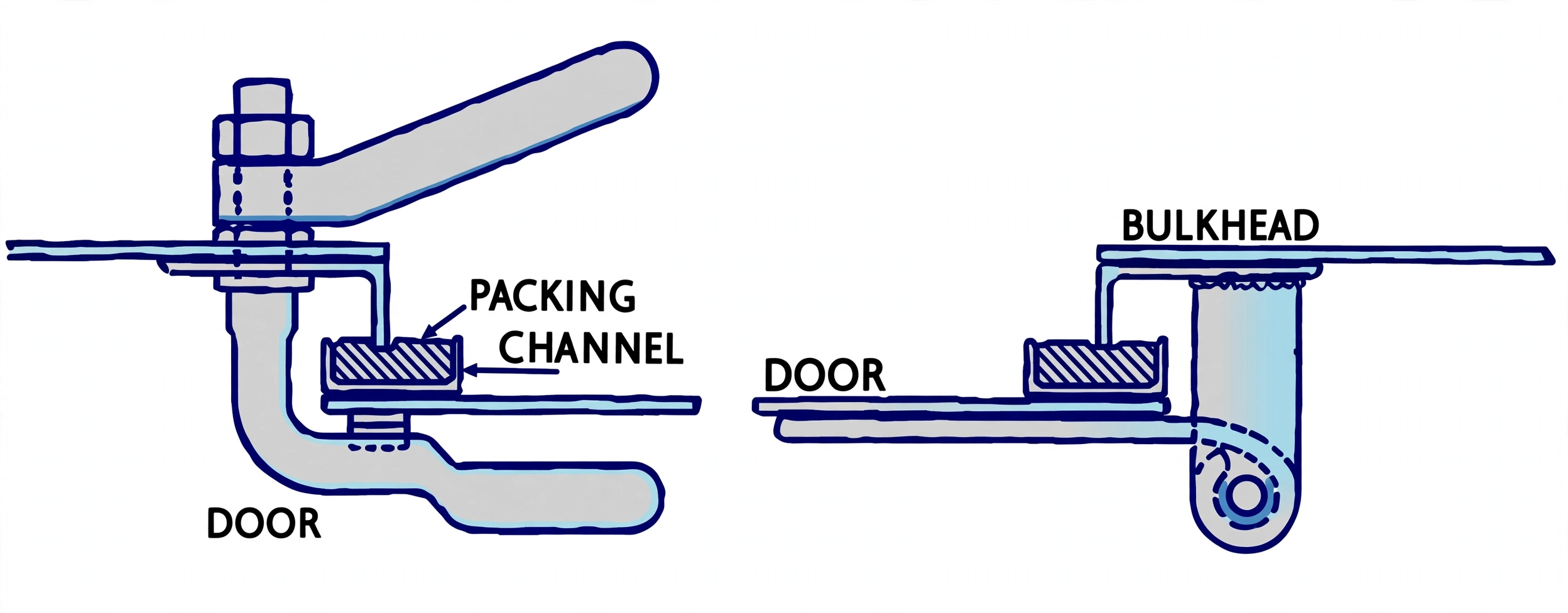
- Class 1 — Hinged Doors: Hand-operated only. Permitted only on passenger ships above decks that are at least 2.2 meters above the deepest load waterline, and on weather deck access openings of cargo ships. Secured by quick-acting dog clips forced against brass wedges.
- Class 2 — Hand-Operated Sliding Doors: Can be either vertically or horizontally sliding. Operable manually by hand crank gear locally at the door, as well as from an accessible control position located above the bulkhead deck.
- Class 3 — Power-Operated Sliding Doors: The statutory standard for all watertight doors located below the waterline in cargo and passenger vessels (such as between the engine room and shaft tunnel). Operated by an electro-hydraulic unit or electric motor, capable of simultaneous or individual remote closure from the Navigation Bridge, while retaining full local control and manual backup.
Orbit the bulkhead and select any part to isolate it. Switch modes to compare the Class 1 hinged, Class 2 manual sliding, Class 3 power sliding and vertical sliding doors. Use Full Screen to view the model without the side panel.
2. Horizontal Power-Operated Sliding Doors (Class 3 Anatomy)
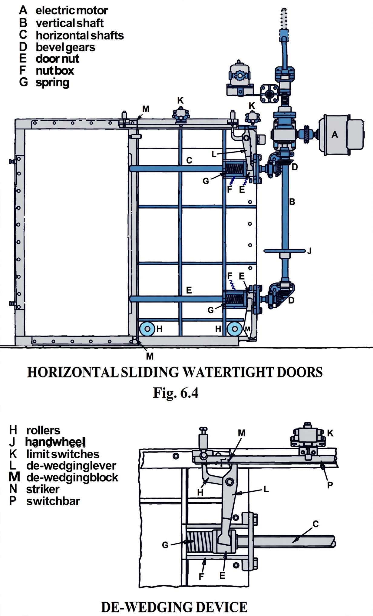
The Horizontal Power-Operated Sliding Watertight Door is the engineering workhorse installed in lower machinery compartments, shaft tunnels, and cargo pipe tunnels. It consists of a heavy cast steel or fabricated plate panel sliding horizontally on hardened steel rollers across a tapered frame.
Key Mechanical Subsystems:
3. Vertical Sliding Doors & Bulkhead Deck Spindles
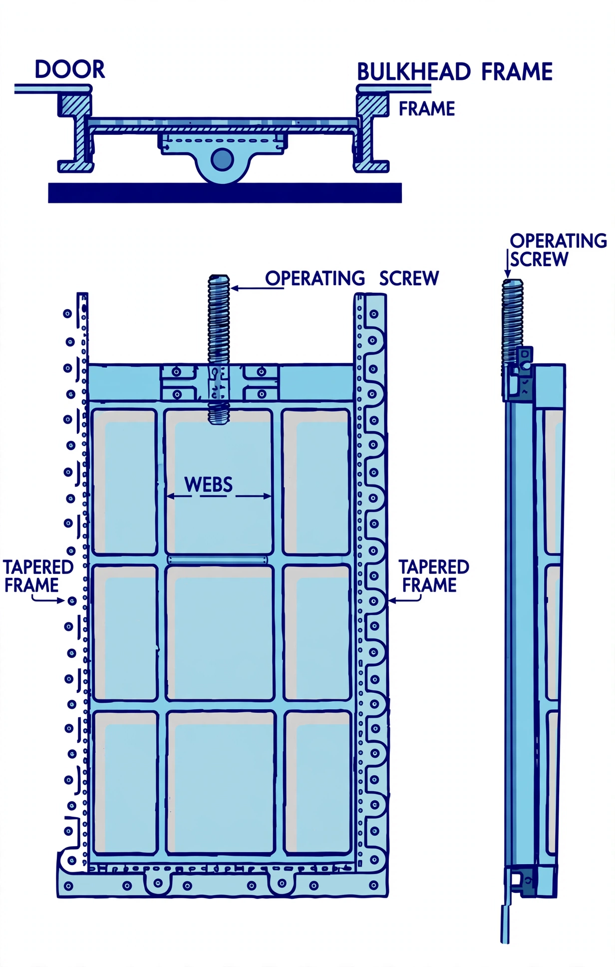
In narrow compartments where horizontal space on the bulkhead is occupied by structural stiffeners, pipe runs, or electrical trays, Vertical Sliding Watertight Doors are preferred.
Drive Mechanics & The Spindle Extension:
A vertical sliding door is raised and lowered by a central vertical screw-threaded spindle turning within a heavy gunmetal nut firmly bolted to the top of the door panel:
- Extended Spindle to Bulkhead Deck: The vertical spindle shaft extends continuously upward through intermediate decks to reach a manual crank operating station situated above the uppermost continuous bulkhead deck.
- Universal Joints & Expansion Couplings: Because the ship hull flexes in ocean waves, the long spindle shaft incorporates universal joints (Cardan joints) and expansion sleeves to prevent binding or bending under hull deflection.
- Mechanical Tell-Tale Indicator: A visual mechanical indicator is directly geared to the upper spindle, clearly showing crew members on the bulkhead deck whether the door below is
FULLY OPEN,IN MOTION, orFULLY CLOSED & WEDGED.
Classification societies strictly forbid any recessed guide groove along the bottom sill of a vertical sliding door! If a bottom groove were present, loose coal, grain dust, metal shavings, scale, and dirt would inevitably pack into the recess, preventing the door from fully seating and destroying its watertight seal. Instead, the vertical guides terminate smoothly above the floor plate, and wedging action on the side frames pulls the flat bottom edge flush against the floor sill.
4. Watertight vs. Weathertight Doors & Emergency Power Rules
In oral exams, surveyors frequently probe a candidate's understanding of the distinction between Watertight and Weathertight doors, as well as the independent emergency power reserve rules mandated by SOLAS:
| Engineering Feature | Watertight Door (WTD) | Weathertight Door (WTD-Deck) |
|---|---|---|
| Location | Below the waterline / Bulkhead deck in transverse watertight bulkheads. | On weather decks, superstructure entrances, and companionways above the waterline. |
| Pressure Capacity | Withstands a continuous hydrostatic water head of 3 to 10 meters (tested up to 20 m / 2.0 bar). | Resists dynamic weather, wind, rain, and brief green-sea wave wash (no continuous submerged head). |
| Sealing Method | Machined brass facing strips forced into tight metal contact by tapered wedges. | Resilient neoprene or hollow rubber gaskets compressed by rotating dog clips. |
| Surveyor Testing | Hydrostatic Pressure Tank Test: Door mounted in a test rig and pressurized with water from the inside (worst-case flooded compartment scenario). | High-Pressure Hose Test: Minimum 12 mm nozzle spraying 2.0 bar water jet from 1.5 m distance across all gasket edges. |
SOLAS Emergency Power & Accumulator Reserve Rules:
Because a ship in a flooding emergency may lose main electrical generators and develop an extreme list, SOLAS Chapter II-1 enforces stringent redundancy requirements for Class 3 power doors:
- Emergency Power Source: Every power-operated sliding door must be connected to the vessel's Emergency Switchboard (powered by the Emergency Diesel Generator).
- Independent Hydraulic Accumulator: Each door must have an independent hydraulic accumulator (or dedicated battery pack) with sufficient stored energy to operate the door at least three consecutive times (Close – Open – Close) without any electrical power input.
- Adverse List Capability: The power system must be capable of closing the door against an adverse static list of up to 15 degrees and a trim of 5 degrees.