
Shaft Tunnel Construction & Line Shaft Bearings
Why the tunnel is offset from the centreline, how watertight ring stiffeners are graded, and how shaft stools transfer loads into the double bottom.
Key Principles at a Glance 6 points
- A shaft tunnel is a watertight passage built around the main shafting where one or more cargo holds separate the machinery space from the after peak, protecting the shaft from cargo contact and giving permanent access for inspection and repair.
- The tunnel runs from the after machinery space bulkhead to the after peak bulkhead and is built off the centreline, normally providing a single passage down the starboard side of the shaft.
- The tunnel top is usually circular, but becomes flat where it passes through a deep tank; stiffening rings are fitted inside the tunnel, except in insulated ships and deep-tank crossings where they are mounted outside.
- Tunnel plating and stiffeners must be strong enough to withstand water pressure without appreciable leakage if flooded, so scantlings are equivalent to those of a watertight bulkhead (tunnel top plating increased by 2 mm under hatches unless wood sheathed).
- One side plate is arranged to be easily removed together with its stiffeners so the main shafting can be unshipped without cutting the tunnel.
- The tunnel doubles as a pipe tunnel carrying services along the tank top over a light metal walking platform fitted about 0.5 m above the tank top, and the shaft is supported at intervals by bearings mounted on shaft stools.
1. Purpose & General Arrangement of the Shaft Tunnel
On many single-screw and some twin-screw vessels, the machinery space is divided from the after peak by one or more cargo holds. The main shafting must therefore be carried straight through these holds to reach the propeller at the stern. Instead of leaving the rotating shaft exposed, a shaft tunnel is built around it.
Why the Shaft Tunnel Exists:
- Protection: It physically encloses the shaft to prevent contact with the cargo, avoiding cargo damage and contamination of the shaft bearings.
- Access: It gives engineers access to the shaft at all times for maintenance, inspection, greasing, and repair while the vessel is at sea.
- Watertight Boundary: The tunnel is watertight and extends from the after machinery space bulkhead to the after peak bulkhead, so a shaft failure or gland leak cannot flood the cargo holds.
Off-Centre Passage Layout:
It is not necessary to provide a passage on both sides of the shaft. The tunnel is therefore built off the centreline of the ship, allowing a passage down the starboard side of the shaft. This keeps the structure compact while still giving a clear walkway for the engineers.
Tunnel Top Profile:
The top of the tunnel is usually circular, which is the strongest and simplest form. However, where the tunnel passes through a deep tank, it is more convenient to fit a flat top so the tank boundary remains simple and the tank can be worked around the tunnel.
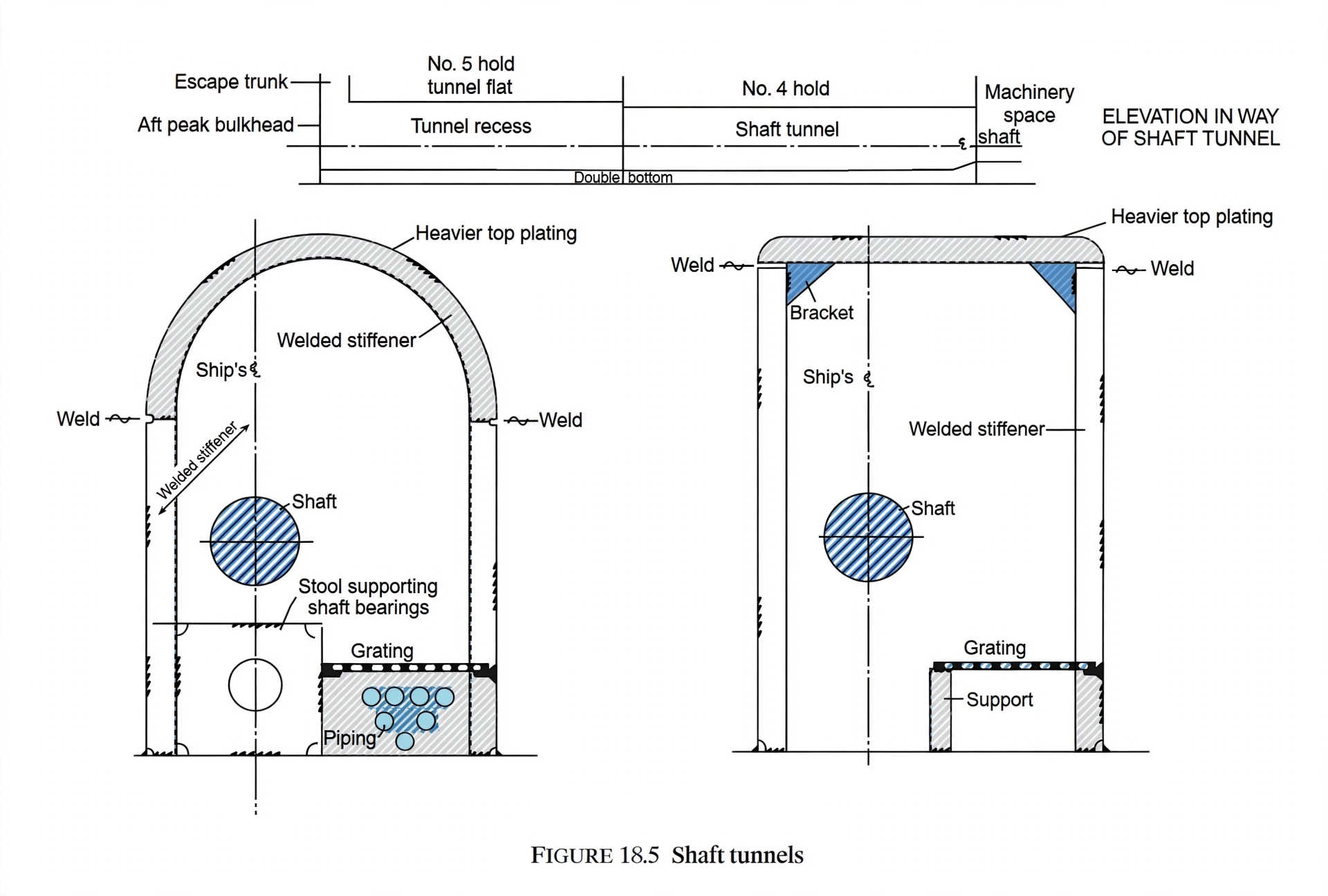
2. Watertight Construction: Ring Stiffeners & Plating Scantlings
The shaft tunnel is, in effect, a long watertight bulkhead arrangement bent around the shaft. Its structure must resist the hydrostatic pressure of a flooded hold without appreciable leakage, so it is built to the same standard as a watertight bulkhead.
Stiffening Rings:
- Rings inside the tunnel: The tunnel stiffeners or rings are normally fitted inside the tunnel, clear of the watertight boundary, so the smooth external face resists water pressure cleanly.
- Rings outside: In insulated ships, and in tunnels that pass through deep tanks, the rings are fitted outside the tunnel to preserve the clean internal finish and tank boundary.
- Fixing the rings: The rings may be welded to the tank top or connected by angle lugs, anchoring the tunnel to the double bottom structure below.
Plating & Boundary Connections:
- The plating is attached to the tank top by welding, or by a boundary angle fitted on the opposite side of the plating to the stiffeners.
- Stiffeners and plating must withstand water pressure without appreciable leakage in the event of flooding; scantlings are therefore equivalent to those required for a watertight bulkhead.
- Under the hatches, the tunnel top plating is increased by 2 mm unless wood sheathing is fitted, to absorb impact from cargo gear and grab discharges.
The Removable Side Plate:
One of the side plates is arranged so that it may easily be removed, together with its stiffeners, to allow the main shafting to be unshipped during a major shaft or bearing renewal. This is the classic surveyor question: "How would you withdraw the main shaft?"
3. Pipe Tunnel Services, Shaft Bearings & Stools
Because the tunnel already forms a protected passage along the length of the double bottom, it is used as a pipe tunnel. Pipes are carried along the tank top, with a light metal walking platform fitted about 0.5 m from the tank top so the engineers can move clear of pipe runs and shaft couplings.
Supporting the Shaft:
The main shaft is supported at intervals by bearings fitted on shaft stools. These stools are critical to alignment and load transfer:
- Accurate line-up: The tops of the stools are lined up accurately to suit the height of the shaft, though final adjustments to bearing height are made when the ship is afloat, since the hull deflection under load changes the alignment.
- Construction: The stools are constructed of 12 mm plates, riveted or welded together, with welding being the most usual modern practice.
- Attached to tunnel rings: The stools are attached to the tunnel rings to prevent movement of the bearings, which could otherwise lead to damage of the shaft or its journals.
- Load path: The loads from the bearings are transmitted to the double bottom structure by means of longitudinal brackets.
- Manholes: Manholes are cut in the end plates to reduce weight and to allow inspection and maintenance of the stools.
4. Inspection, Safety & Emergency Escape
Because the shaft tunnel is a confined, watertight space that penetrates several cargo compartments, its operational safety procedures are as important as its structure.
Routine Inspection:
- Bearing condition: Line shaft bearings and their lubrication are checked regularly for overheating and wear, since a seized bearing can crack the tunnel or damage the shaft.
- Leakage watch: Any weeping at the tunnel boundary, bulkhead penetrations, or stuffing boxes is investigated immediately to preserve the watertight integrity of the cargo holds.
- Structure: Ring stiffeners, brackets, and plating are examined for corrosion, cracked welds, and deformation during surveys.
The shaft tunnel is a long, low, confined passage with only limited openings. In the event of shaft failure, stern gland leakage, or a tunnel flood, escape can become impossible if the exits are blocked:
- Two exits: The tunnel must always provide an escape route at each end — into the machinery space forward and up to the deck aft via the after peak / steering gear space.
- Watertight doors: Watertight doors at the tunnel ends are kept closed at sea and clearly marked; they must never be clipped open.
- Enclosed space entry: Entry follows the standard enclosed-space procedure — permit, atmosphere testing, ventilation, standby man, and communication.
- Flooding: On detection of flooding, the tunnel is evacuated, watertight doors are closed, and the bilge/emergency pump is used only if it is safe to do so.