
Shipbuilding Materials, Welding and Weld Defects
What the structure is made of and how the pieces are fastened — mild and high tensile steel, aluminium, the sections used as stiffeners, and the NDT that finds what a weld hid.
Key Principles at a Glance 8 points
- Hull mild steel carries 0.15 to 0.23 per cent carbon with reasonably high manganese, and both sulphur and phosphorus are held below 0.05 per cent.
- The two limits are held for different reasons: sulphur makes the steel hot short so the ingot tears during rolling, phosphorus makes it cold short and degrades the weld.
- High tensile steel is used in the most stressed regions — the deck and bottom of large tankers, container ships and bulk carriers — because it lets the scantlings come down.
- Aluminium alloys, 5083 plate and 6082 extrusion, save up to 60 per cent of the weight of a superstructure or hatch cover, against eight to ten times the price and the need to insulate it from the steel.
- A plate is stiffened rather than thickened because stiffening buys the same section modulus for far less weight.
- The stiffener section follows the span: flat bar where it is short, angle where it is longer, bulb or T where it is longer still.
- Slag-shielded processes weld the bulk of the hull because they are portable and work in all positions; submerged arc is kept for long downhand seams; inert-gas processes for thin plate and aluminium.
- The inspection method follows the defect: surface flaws by magnetic particle or dye penetrant, near-surface by eddy current, and anything inside the joint by ultrasonic or radiographic testing.
5.1 The materials
What the structure is made of, and how the pieces are fastened. The framing systems of Part 6 are chosen partly for weldability, and a weld defect is the one fault that cannot be seen from the deck — so the inspection methods at the end of this part are as much a part of the structure as the plates.
5.1.1 Mild steel
Steel is a highly versatile ship construction material and is used extensively on ships for the making of the integral structure and parts. One major drawback is its weight. For the construction of the hull of a ship, mild steel containing 0.15% to 0.23% carbon, and reasonably high manganese content, is used.
The two residual elements are held down deliberately:
| Element | Limit | Reason |
|---|---|---|
| Sulphur | Kept to a minimum, less than 0.05% | Higher content hampers the welding properties of the steel, and cracks can develop easily during the rolling process if the sulphur content is high |
| Phosphorus | Kept to a minimum, less than 0.05% | Higher content hampers the welding properties of the steel |
The two reasons are worth keeping apart, because they are asked together and they are different failures. Sulphur is the worse of the two: it is the element that makes the steel hot short, so the ingot tears during rolling while it is still hot. Phosphorus makes it cold short, and it is this one that degrades the weld. Both effects are why the limits sit together in the specification.
5.1.2 High tensile steel
High tensile steels, which have higher strength than mild steel, are employed in the more stressed regions of large tankers, container ships and bulk carriers. They are often used for the deck and bottom regions of larger tankers as well.
The reason is the one established in Part 4: these are the regions doing the work as the top and bottom flanges of the hull girder, and a higher allowable stress there lets the scantlings come down. As this leads to a reduction in the scantlings of those structural items, it proves advantageous both for the shipbuilder and the owner — less steel to buy and to weld, and less weight in the ship for the same strength.
5.1.3 Aluminium alloys
There are three main advantages which aluminium alloys have over mild steel in the construction of ships:
| Advantage | Detail |
|---|---|
| Weight | Aluminium is lighter than mild steel, and studies suggest that up to 60 per cent of the weight of a steel structure can be saved by using Al alloys. For merchant vessels this is a key advantage for increasing the cargo carrying capacity of ships. |
| Corrosion | Aluminium is highly resistant to corrosion. |
| Non-magnetic, cheap to keep | Its non-magnetic properties, and low-cost maintenance. |
The saving is worth stating in the form the oral wants it: it is not 60 per cent off the weight of the ship, it is up to 60 per cent off the weight of a steel structure of the same size — the superstructure, a deckhouse, a hatch cover. The steel hull below stays steel.
The alloys. The most often used Al-alloys in shipbuilding are the 5083 type for plates and 6082 for extrusions. These alloys are reliable in marine service as well as during manufacture. It has been estimated that the selection of Al-Mg (aluminium-magnesium) type alloys brings a potential for at least 10 per cent lower costs in respect of the heat-treatable, and appears favourable after a total estimation for applicability in shipbuilding.
The disadvantages:
- Cost. The major disadvantage is the high initial cost — aluminium alloys are estimated to cost 8 to 10 times the price of steel per tonne. This high initial cost must be absorbed by an increase in the earning capacity of the vessel, or a major increase in passenger accommodation on the same draft.
- Insulation against steel. Excellent corrosion properties of aluminium can be used easily, but correct maintenance procedures and careful insulation from the adjoining steel structures are necessary when using this material.
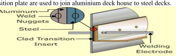
The insulation is not optional and is not about water. Aluminium and steel in contact form a galvanic couple in the presence of sea water, and the aluminium — being the less noble of the two — is the one that is eaten. The transition detail that solves it is the clad transition insert, which joins aluminium to steel decks: aluminium one side, steel the other, weld nuggets at each end, welded on with the normal electrode.
What the aluminium is bought for, in the end, is the whole chain of consequences: aluminium alloys can replace carbon steels of normal strength, the weight saved by using Al alloys improves the ship stability — and allows the design of narrower ships, which in turn enhances fuel efficiency.
5.1.4 Where each material is used in the ship
The materials list is short, but where each is used is a standard question. Taken as the set:
| Component | Material and reason |
|---|---|
| Shell plating | Steel. Forms the watertight skin, contributes to the longitudinal strength of the structure and resists vertical shear forces. Bottom and side shell plating consist of several flat and curved steel plates butt welded together, of greater length than breadth |
| Insulation | A steel hull is an excellent conductor of heat, so some form of insulation is required at boundaries where a temperature is to be maintained, such as refrigeration compartments. Cork, glass fibre, and foams in sheet or granulated form; air spaces are used but are less efficient. Glass fibre is widely used in modern ships: light, vermin-proof, does not absorb moisture, and fire-resistant |
| Superstructures | Aluminium alloy. Gives increased passenger accommodation on the same draft, and/or a lowering of the lightweight centre of gravity with improved stability; hence used on passenger and cruise ships. More significant deformation can be accepted in these superstructures than would be possible with steel, because of the lighter weight of the aluminium structure |
| Watertight doors | Mild steel or cast steel below the waterline: they prevent flooding of the compartments when shut while providing adequate strength in an emergency. Fitted where access is needed between compartments on either side of a watertight bulkhead — between machinery space and shaft tunnel in a cargo ship, and in passenger ships where passengers pass from one part of the accommodation to another |
| Rudder | Fabricated from steel plates and sections with plate sides stiffened by internal webs. Internal surfaces are suitably coated against corrosion, and the rudder may be filled with inert plastic foam |
| Rudder pintle | A bolt or pin inserted into a gudgeon to attach the rudder to the ship. Older ships had a brass or bronze liner shrunk on the pintle turning in hardwood (Lignum Vitae) bearings in the gudgeon; present practice is synthetic materials such as Tufnol for bearings, and in some cases stainless steel for liners. In either case the water which immerses the bearing lubricates it |
| Rudder stock | Cast or forged steel, its diameter determined by the torque and any bending moment it is to withstand |
| Propellers | Copper alloys such as brass, to withstand the corrosive effect of salt water. Designed to minimise cavitation — the forming of water-vapour bubbles in the low-pressure region of a heavily loaded blade, which then burst next to the blade and blast little pits into the surface |
| Stern frame | Supports the rudder and the propeller. May be cast, forged, or fabricated from steel plate and sections; modern rudders are also fabricated from steel plates |
5.1.5 Cathodic protection
Where two dissimilar metals are immersed in sea water, one of them is consumed. The remedy is deliberate: the fitting of zinc plates in way of bronze propellers and other immersed fittings, used as sacrificial anodes, is common practice in shipbuilding. These anodes are metals or alloys attached to the hull which have more anodic potential than steel when immersed in sea water. They supply the cathodic protection current, and are consumed in doing so; regular maintenance and replacement are therefore required.
Modern anodes are based on alloys of zinc, aluminium, or magnesium, tested for suitability; high-purity zinc anodes are also used. Sacrificial anodes are fitted on the hull and also often in ballast tanks.
The whole subject belongs with the corrosion prevention of the hull, where the second of the two measures is named as cathodic protection, and its two forms as the sacrificial anode system and the impressed current system.
5.2 Sections and stiffeners
5.2.1 Why primary plating must be stiffened
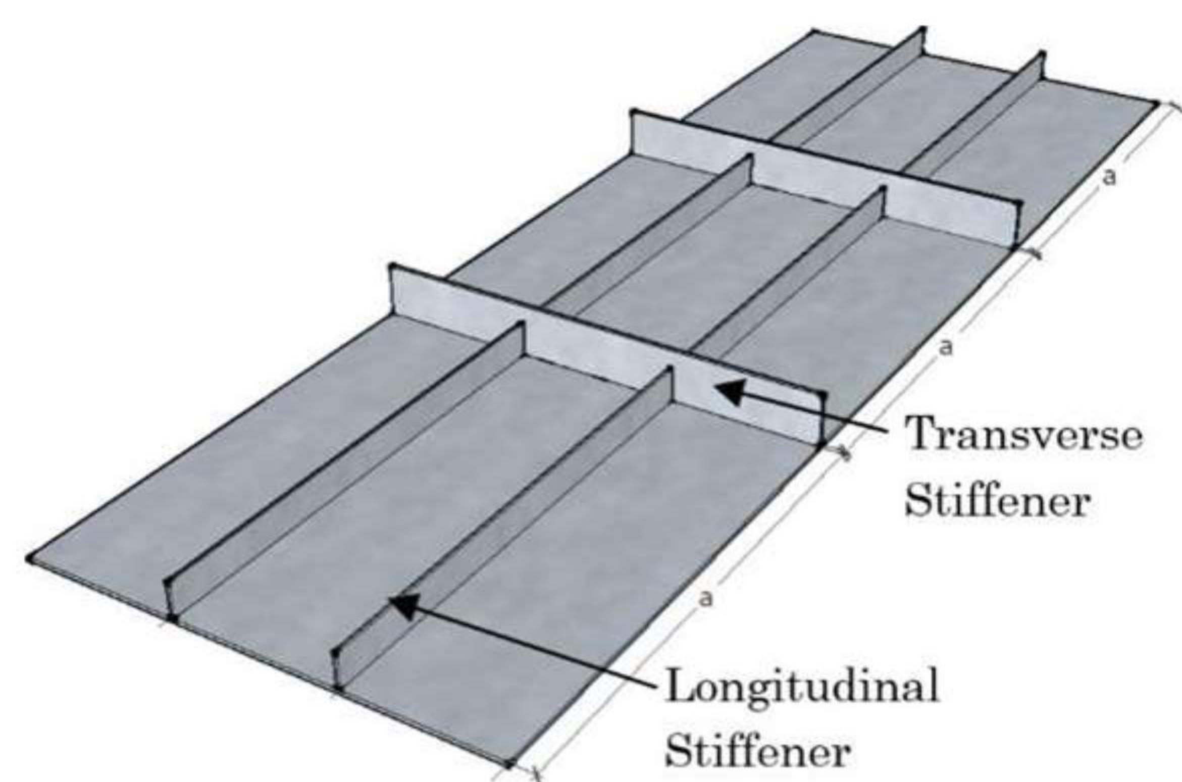
The strength of any primary plate can be increased by increasing its thickness uniformly along its length and breadth. As strength increases, the weight of the plate also increases — and hence this option is not recommended in ship construction, because it increases the light weight of the ship.
To overcome this problem, a variety of plates and stiffeners are welded to the primary plates along length and width, which increases the strength of the primary plating by adding only a minimum amount of weight.
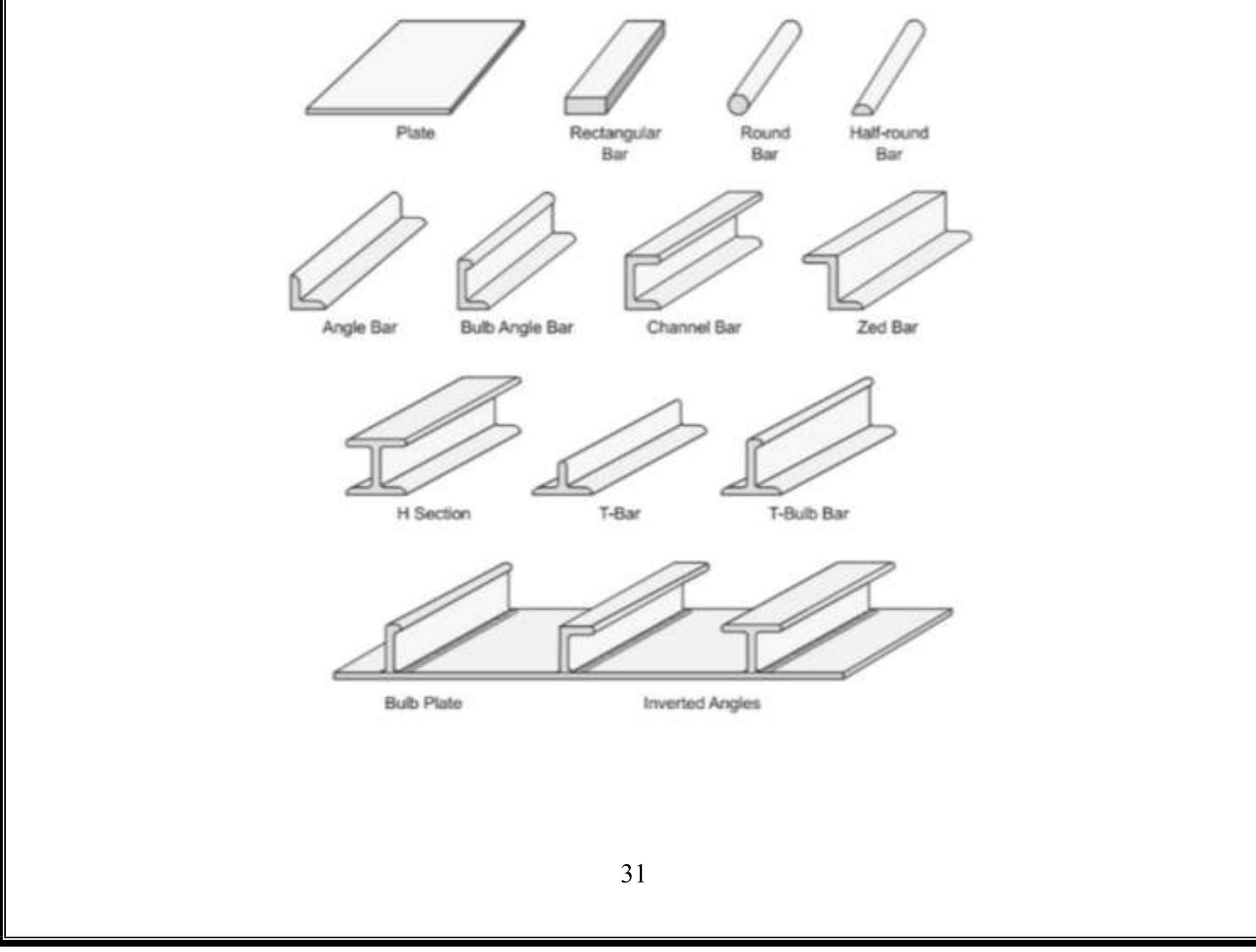
Stiffeners are secondary plates or sections which are attached to primary plating to stiffen them against bending to loads. The set of cross-sections used in shipbuilding:
| Group | Sections |
|---|---|
| Bars | Plate · rectangular bar · round bar · half-round bar |
| Angle and bulb | Angle bar · bulb angle bar · inverted angle |
| Other rolled sections | Channel bar · zed bar · H section · T-bar · T-bulb bar · bulb plate |
5.2.2 Flat bar stiffeners
A flat bar is a plain rectangular section, its depth being the dimension that resists the bending. It is the section used where the stiffener has only a short span to carry, or where the space behind it must be kept clear — the standard example being the plate floors, which are further stiffened by flat bar stiffeners.
The reason a flat bar is enough in that position is the one established in Part 4: the buckling strength of a stiffener is a question of its depth, and a flat bar is the least material that gives a given depth. What it lacks is lateral stiffness, which is why it is used where its unsupported length is short and where an angle strut or a bracket is provided to stop it warping.
5.2.3 Angle stiffeners
An angle bar is an L-section. Compared with a flat bar of the same depth it carries its material further from the plate, which gives it a greater section modulus for the same weight, and its flange gives it lateral stiffness that a flat bar does not have.
That is why the bracket floors are stiffened by angle struts to prevent warping, and the plate floors by flat bar stiffeners. The flat bar goes where the stiffener is short and only needs depth; the angle goes where the unsupported length is greater and the section would otherwise twist. An angle strut in this position is doing exactly the same job as a stiffener: it is holding two surfaces apart and preventing the panel between them from buckling.
The same reasoning runs through the whole ship. Small brackets and short spans take flat bar; long unsupported runs take angle; and where the span is longer again the section becomes a bulb angle, a T-bar or a T-bulb bar, because the bulb or the table of the T is what keeps the stiffener from tripping sideways when the plating it carries is under compression.
5.3 Welding
5.3.1 The three techniques and the whole method tree
The three main welding techniques used in a shipyard:
The tree is worth memorising as a tree, because the two branches under arc welding are distinguished by one thing only: what shields the arc from the air — slag, or an inert gas.
5.3.2 Arc welding — the principle and the circuit
The fundamental principle of arc welding is to connect a metal electrode to an electrical power supply, forming a closed circuit if the plate is touched with the electrode.
When the electrode is raised from the plate by a few millimetres, the electric current jumps the gap and an electrical arc is created at high temperature. This melts the parent metal and the metal in the electrode, allowing both metals to fuse.
The circuit is a generator with voltage control and current control, connected through an electrode to the workpiece, with the arc struck between electrode and plate.
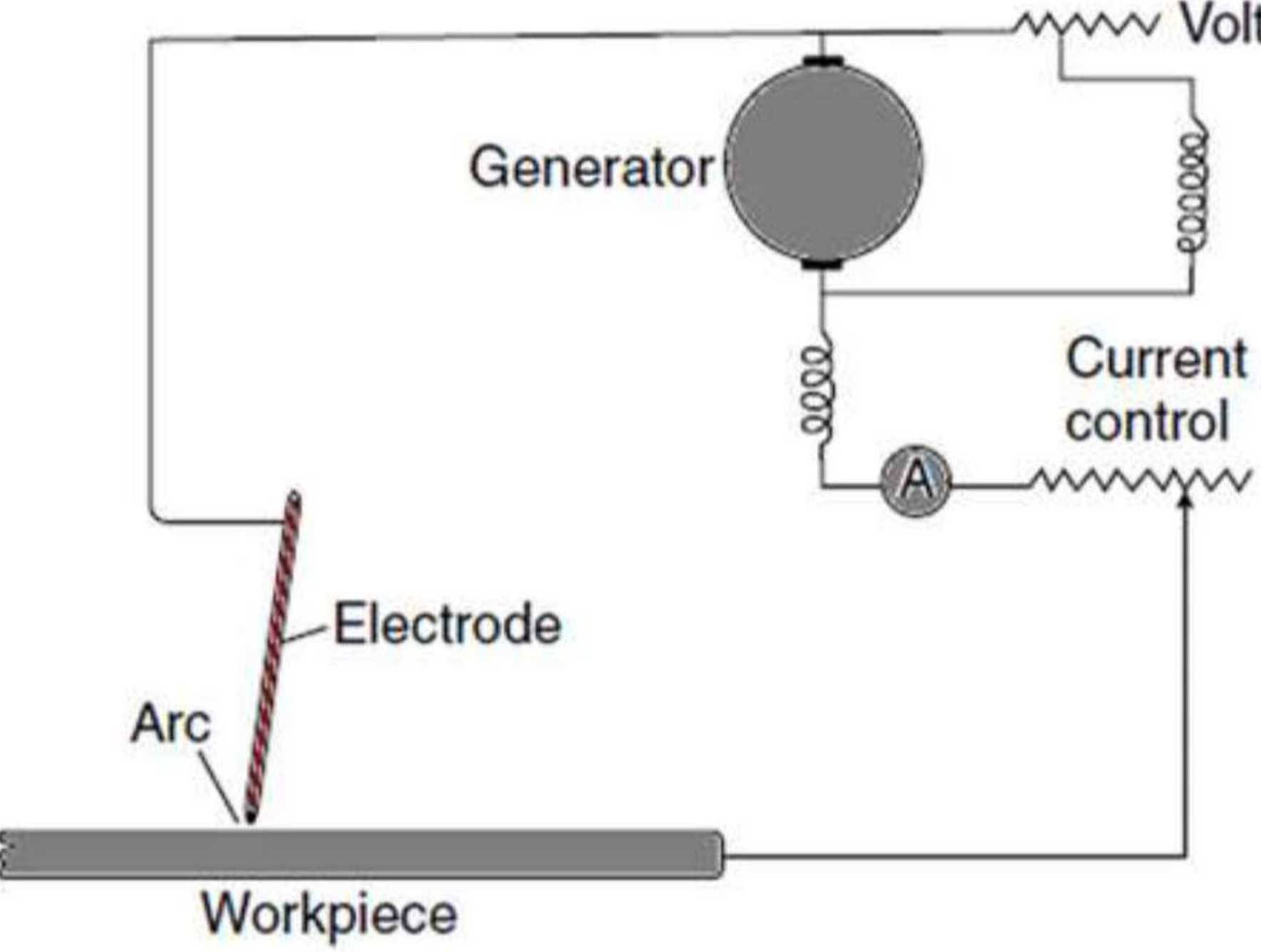
The two controls are doing different jobs, and they are the source of most welding defects. The current setting decides how much heat is put in, and therefore how deeply the parent metal melts. The voltage setting decides the length of the arc. Getting one of them wrong produces a defect with a name — which is why the defect list in §5.4 reads the way it does.
5.3.3 Arc shielding, and why oxidation must be prevented
Arc shielding is an important aspect of all arc welding processes. In order to prevent the oxidation of the fused metal, the arc is shielded from the ambient air, and contact with oxygen and water vapour is cut off.
Why it matters: at arc temperature the steel is molten and has a strong affinity for oxygen. If air reaches the weld pool, the oxygen combines with the metal and the result is oxide inclusions and gas pockets in the finished weld. The shield is therefore not protecting the welder — it is protecting the chemistry of the joint, and both the slag and the inert gas methods exist for that single reason.
The two mostly used shielding techniques used by shipyards are slag shielded arc welding and inert gas shielded arc welding.
5.3.4 Slag shielded arc welding
Slag is the residue left over after the parent metals and the electrode metal have fused. It forms a layer over the arc and the welded joint, protecting it from oxidation. The presence of slag also stabilises the arc, providing a better weld quality.
Three processes are used in shipyards.
5.3.4.1 Shielded metal arc welding (SMAW)
The filler metal of most electrodes used in the shipbuilding industry is mild steel. Mild steel drawn in the form of rods is coated with a mixture of mineral oxides, fluorides, silicates, hydrocarbons, and a liquefied binder which binds them together into a solid envelope around the filler metal. This coating forms the slag, stabilises the arc and prevents oxidation of the joint.
Shielded metal arc welding is used in the fabrication of panels, grillages, tank units and so on. It is used in manual arc welding, and can achieve welding in the different positions:
- Downhand welding.
- Overhead welding.
- Vertical welding.
The coating is the whole point of the process. The same rod both supplies filler and generates its own shield, which is why it is the portable process — no flux hopper, no gas bottle, no carriage — and why it is the one used for the positions a machine cannot reach.
5.3.4.2 Submerged arc welding (SAW)
The arc is struck and maintained under a blanket of granulated flux laid on the weld joint before the arc strikes. A hopper containing granulated flux runs along the length of the joint and deposits the blanket. The hopper is followed by a trolley carrying the filler metal electrode, which is continuously fed by rollers driven by a drive motor, the feed rate being set so that the electrode tip is always submerged within the flux. The arc is hence generated within the layer of flux, allowing complete insulation from the environment.
Three parameters are pre-decided according to the thickness of the plates, the material of the parent metal, and the quality of joint required: the speed of movement of the trolley, the feed rate of the electrode, and the amount of flux on the joint.
Submerged arc welding is the most commonly used downhand welding method in the shipbuilding industry, owing to its arc stability and quality of joint. Since most of the joints are welded on one side, a backing strip made of ceramic material is placed under the joint to prevent the flow of the weld bead from the other side.
The arc cannot be seen in this process, because it is buried in the flux — hence "submerged". That is also why it can be run at a far higher current than a coated rod without the heat escaping, and why it is the process for long straight seams on flat panels.
5.3.4.3 Stud welding
Used where a stud or bolt is to be welded to a parent metal. The stud is fixed at the muzzle of the stud welding gun. When the gun is fired, the stud is struck onto the metal; the high velocity of the stud together with the completed electric circuit generates the arc which fuses both metals. Once the stud has been driven into the metal the electrical supply is automatically cut off. Granular flux is contained at the end of each stud to provide insulation from the air and prevent oxidation of the weld pool.
This process is used for fastening insulation panels to bulkheads, and wooden flooring onto deck plates. It is not a structural welding process at all: it is a fixing method, and the studs it produces are the ones that later hold the ship's ceilings, linings and deck covering.
5.3.5 Inert gas shielded arc welding
Gas shielded arc welding processes use a blanket of gas, instead of flux, to insulate the arc against the ambient environment. They are used extensively in shipyards for welding the comparatively lighter structures.
5.3.5.1 Tungsten inert gas welding (TIG)
The arc is created between a non-consumable tungsten electrode and the parent metal plates. The tungsten electrode is surrounded by a nozzle that maintains a continuous flow of inert gas around the arc. This inert gas shields the arc from oxygen, hence stabilising it and preventing oxidation of the weld pool. A filler rod is introduced into the arc, which helps in the fusion of the two metals. The inert gas used is usually argon. TIG welding is preferred for plates of thickness usually less than 6 to 8 mm.
The electrode does not melt, so the filler is added separately and by hand: the welder controls heat and filler independently, which gives the cleanest weld of any process and the slowest deposition rate. That pairing is why it is kept for thin plate and for the work where quality matters more than speed, such as pipe joints and aluminium.
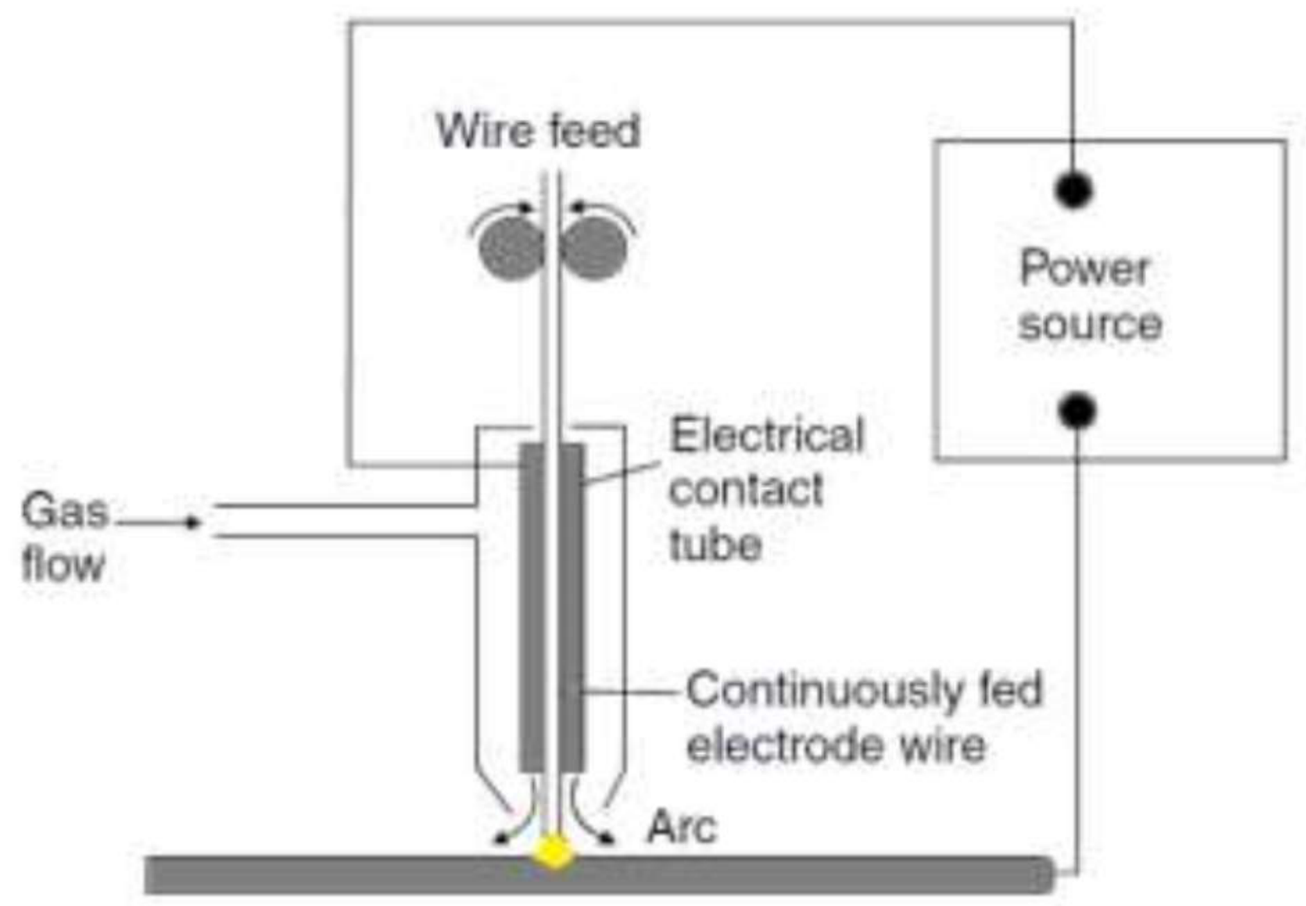
5.3.5.2 Metal inert gas welding (MIG)
Metal inert gas welding is, in a way, an advancement on TIG, where the electrode is a consumable metal wire.
The welding torch consists of an electrical contact tube which connects the electrode wire to the power supply. The electrode wire is continuously fed into the nozzle by a pair of driver rollers and passes through the electrical contact tube. The flow of an inert gas is maintained into the torch through a separate line, creating a blanket of inert gas around the stabilised arc.
Carbon dioxide is the most widely used inert gas for this purpose. MIG welding has been widely used in welding aluminium deckhouses and spherical membrane tanks in liquefied gas carriers.
5.3.6 Gas welding
In addition to arc welding, gas welding is named among the main techniques used in a shipyard, and it is the second heading under which the inert gas processes are set out, before TIG and MIG. In gas welding the heat comes from the combustion of a fuel gas with oxygen rather than from an electric arc, and no electrical circuit is involved. What matters for the oral is that it is one of the three, and that it is not the same thing as the gas shielded arc processes with which it shares a name.
5.3.7 The filler rod and its function
A filler rod is introduced into the arc. Its function is to supply the additional metal needed to fill the joint, and in doing so it helps in the fusion of the two metals.
It is the distinction from the electrode that is being examined here. In TIG the tungsten electrode is non-consumable and supplies no metal at all: the whole of the weld metal is the separately added filler rod. In MIG and in SMAW the electrode is consumable, so although a filler is fed into the arc it is the electrode wire or rod itself that is the filler. Either way the filler's job is the same — to bring the parent metals to a common pool and make good the joint.
5.4 Weld defects
Every weld joint is inspected by a team of trained inspectors for weld defects. Weld defects may arise due to lack of skill in welders, use of incorrect materials, or improper welding methods and ambient conditions.
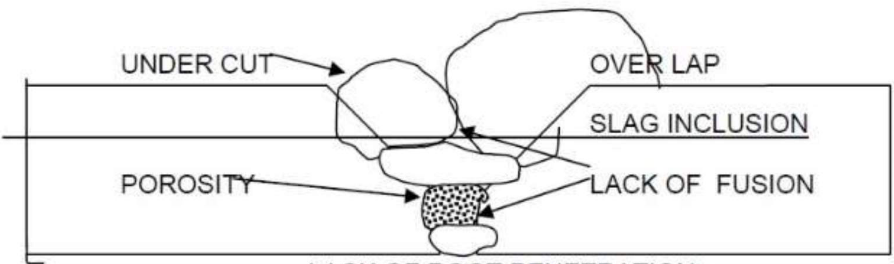
The most common weld defects:
Undercut · porosity · overlap · slag inclusion · lack of fusion · lack of root penetration.
Two more are named in the same section and belong to the same list for the oral: distortion, and centre line cracking.
5.4.1 Overlap
Overlap is an overflow of weld metal over the base metal without fusion. Failure of the joint is certain when the overlap is located at the toe of the weld. It is one of the serious welding defects on ships and should be avoided.
Causes:
| Cause | What it does |
|---|---|
| Low welding current | Not enough heat to melt the base metal under the deposited metal |
| Fast travel | The pool is laid down faster than the base metal can be brought to fusion |
| Improper electrode manipulation | Molten metal runs onto cold base metal |
The mechanism is the same in all three: molten weld metal is deposited on base metal that never reached its melting point, so there is a mechanical discontinuity rather than a weld. At the toe it is the worst possible place for it, because the toe is already the point of stress concentration.
5.4.2 Undercut
Undercut is a cutting away of the base metal surfaces at the edge of the weld. It decreases the thickness of the metal at that point. Any material reduction in the metal thickness also reduces the metal strength, thus causing joint failure, since the designed load of the joint is based on the original metal thickness.
The possibilities of failure at this point are increased when undercutting occurs at the toe of the weld, a point where there is high stress concentration.
Causes:
| Cause | What it does |
|---|---|
| Improper arc manipulation | The arc is held where it eats into the parent metal |
| Slow travel | The arc dwells too long at the edges of the joint |
| Excessive welding current | The arc is hot enough to gouge the parent metal |
Note that undercut and overlap come from opposite settings of the same two knobs — overlap from too little current and too fast travel, undercut from too much current and too slow. It is the pair that proves the point made in §5.3.2: the current and the travel speed are the two variables the welder is actually controlling, and a defect name tells you which way he got it wrong.
5.4.3 Porosity
Porosity is the presence of pockets containing gas in the welds. Excessive porosity in metal arc welds has a serious effect on the mechanical properties of the joint.
Causes:
- Overheating and under-heating of the weld metal.
- Too high a current.
- Too long an arc.
The gas has to come from somewhere, and it comes from the atmosphere the shielding failed to exclude, or from moisture and dirt on the joint. That is why porosity is the defect that points back to §5.3.3: it is the direct consequence of the shield not doing its job.
5.4.4 Slag inclusion
Slag inclusions are elongated or globular pockets of metal oxides and other solid compounds. They may be caused by the contamination of the weld metal by foreign bodies. In a multi-layer welding process, failure to remove the slag between layers causes slag inclusion.
Preparing the groove and the weld properly before each bead is deposited can prevent most slag inclusion, making sure that all slag has been removed and cleaned from the surface of the previous bead.
This is the defect that is peculiar to the slag shielded processes — the shield in §5.3.4 becomes the inclusion if it is trapped. The inert gas processes of §5.3.5 cannot produce it, having no slag to trap, which is one of the things the customer is paying for.
5.4.5 Lack of fusion
Lack of fusion is the failure of a welding process to fuse together layers of weld metal, or weld metal and base metal.
It is caused by failure to raise the temperature of the base metal, or of the previously deposited weld metal, to the melting point. Reasons for this failure:
- Too small an electrode.
- Too fast travel.
- Too close an arc gap.
- Too low a welding current.
This is generally referred to as overlap. Worth noting as an equivalence, because the two are not quite the same thing: overlap is a specific geometry of unfused metal at the surface, while lack of fusion is the general condition of the joint not having become one piece.
5.4.6 Lack of root penetration
This is the failure of the filler and the base metal to fuse together at the root of the joint. Lack of penetration will cause weld failure if the weld is subjected to tension or bending stresses.
Causes:
- Incorrect joint design.
- Fast travel.
- Electrodes too large.
- Current setting too low.
The root is the first pass, and on a single-sided weld with a backing strip it is the pass that decides whether the joint is one plate or two. A tension or bending load opens the root gap, which is why this defect is the one that matters most in the shell plating and in any joint carrying the longitudinal bending of Part 4.
5.4.7 Distortion
Distortion is caused by uneven heating and cooling, which involve the expansion and contraction of the base metal.
Methods of control:
| Method | How it works |
|---|---|
| Back-step welding sequences | Heat is distributed so that the contraction of one pass counteracts the next |
| Clamping into a fixture | The parts are held in their original position while the weld contracts |
| Single bead welding | Instead of making two or three passes with small diameter electrodes, one pass is made with a large electrode — less heat input, fewer contraction cycles |
Distortion can also be eliminated by increasing the welding speed and by closing the distance between the parts to be welded.
5.4.8 Centre line cracking
Caused by the inability of the base metal to move when the weld solidifies and contracts, and by using incorrect electrodes, an imbalance of base metal masses, or too high a carbon content in the base metal.
Elimination:
- Design the joint correctly.
- Preheat the parts to be welded prior to welding.
- Maintain the preheat temperature in the base metal during the process.
- Allow the base metal to move freely as the welding takes place.
- Stress relieve the welded parts as soon as the operation is completed.
The mention of high carbon content ties the defect back to §5.1.1: the steel specification holds carbon inside a band for a reason, and one of the reasons is this crack.
5.4.9 The defect table
| Defect | What it is | Classic cause | What it costs |
|---|---|---|---|
| Overlap | Weld metal overflowing the base metal without fusion | Low current, fast travel | Certain failure if at the toe |
| Undercut | Base metal cut away at the weld edge | High current, slow travel, poor arc manipulation | Reduced metal thickness at a stress concentration — the joint was designed for the original thickness |
| Porosity | Gas pockets in the weld | Over- or under-heating, too high a current, too long an arc | Serious effect on the mechanical properties of the joint |
| Slag inclusion | Pockets of metal oxides and solid compounds | Slag not removed between passes | Contamination of the weld metal |
| Lack of fusion | Layers, or weld and base metal, not fused | Small electrode, fast travel, close arc gap, low current | The joint is not one piece |
| Lack of root penetration | No fusion at the root | Incorrect joint design, fast travel, large electrode, low current | Failure under tension or bending stresses |
| Distortion | Permanent movement from uneven heating and cooling | Heat input and restraint | Loss of shape; the plating no longer fits |
| Centre line cracking | Crack along the centre of the weld as it solidifies | Restraint, wrong electrodes, high carbon, uneven masses | A crack in the joint, not beside it |
5.5 Non-destructive testing
5.5.1 The methods, taken as a set
Every weld joint is inspected by a team of trained inspectors. Because none of the defects in §5.4 can be put right after the ship sails, the inspection is not a formality: a weld defect is a defect built into the structure, and the only chance to find it is while the joint is still accessible.
The commonly used non-destructive methods of weld quality inspection:
| Method | What it finds | How |
|---|---|---|
| Visual inspection | Surface defects only | Trained inspector with the naked eye |
| Dye penetrant inspection (DPI) | Surface cracks | Dye seeps into the crack and stays there after the surface is cleaned, showing as a red line against the developer |
| Magnetic particle testing | Smaller surface cracks that DPI misses | Magnetic powder clusters where the magnetic field alters at a crack in a ferrous material |
| Radiographic testing | Subsurface defects | A beam of radiation through the test piece, recorded on a photographic plate on the far side |
The list is built on penetration capability, and that is how it should be answered: visual finds what is on the surface and visible; dye penetrant finds surface-breaking cracks too fine to see; magnetic particle finds them on ferrous material by a different physical route; radiography is the only one of the four that can see inside the weld.
5.5.2 Visual inspection
Carried out by a trained inspector, in which any surface defect is detected with the naked eye. Surface slag deposition, the incorrect shape of weld beads, incorrect alignment of plates and excessive reinforcement on the surface can all be detected this way.
All the under-surface defects, however, require the other methods. The value of visual inspection is that it is free, universal and cannot be avoided — a welder who can see a misaligned plate or an over-thick bead will not produce it. What it cannot do is find anything the surface does not betray.
5.5.3 Dye penetrant inspection — why it is done, and how
Why. This is the most common test method used to detect cracks in components on board ship. The defining property is that the penetrant is the same penetrating oil used to loosen a rusted nut and bolt, except it contains a dye which will find its way into the smallest of cracks, even those invisible to the naked eye.
Two forms of indication:
- Some are fluorescent dye, used in conjunction with an ultraviolet light, which makes the cracks glow green when ordinary lighting is reduced.
- Some are developer, which makes the dye stand out as a red line.
How. The usual form comes in three aerosols, and the sequence is the one to recite:
- Cleaner is sprayed on, and the component is allowed to dry.
- The penetrating dye is sprayed on, and after 5 minutes the excess coating on the surface is wiped off.
- The developer is sprayed on, which will highlight any crack present.
The same test is also given with the developer applied first, as a white layer to aid the eye, and the dye afterwards: the joint is cleaned to remove slag or unwanted material, a layer of developer is sprayed, then the dye, which is usually bright red because that is the most noticeable colour to the human eye. After a sufficient waiting time the surface is cleaned. The cleaning removes all the dye from the surface, but the layer of developer remains; where a crack is present the dye has seeped in, so the crack clearly appears red. The presence of any red lines indicates surface cracks, and corrective measures are then taken.
Both descriptions agree on the mechanism — dye in the crack, developer as the background that makes it visible — and they make the point that the developer is there for contrast, not for chemistry. Use the cleaner first, dry, penetrate for five minutes, wipe, develop, read.
5.5.4 Magnetic particle testing
Smaller cracks are not noticeable in DPI tests, but magnetic particle inspection reveals them clearly, due to the change in magnetic field at the cracks.
The magnetic powder is spread on the weld joint. The alteration in the magnetic field at a crack in a ferrous material causes the magnetic particles to accumulate along the length of the crack, forming clusters in its vicinity. This provides a clear indication of surface cracks.
The word to keep is ferrous. The method works by magnetising the part, and it therefore cannot be used on the aluminium superstructures of §5.1.3 — those are the province of dye penetrant, and of the radiography below.
5.5.5 Radiographic testing
The principle is the subjecting of the test piece to a beam of radiation from one side, and capturing or recording the emitted radiation on a photographic plate on the other side. This is where radiographic testing comes of great use in the detection of subsurface weld defects: any obstacle within the weld joint changes the radiation density in that area, which is reflected on the plate. Hence radiography is basically used to test the consistency of the weld metal.
The physical objection — a slag inclusion, a gas pocket, a crack — absorbs radiation differently from sound metal, so a defect appears on the film as a change of density. That is why radiography is the method of choice for the defects of §5.4 that lie inside the joint: lack of fusion, lack of root penetration, porosity and slag inclusion all show on the film, where no surface method can reach them.
5.5.6 Ultrasonic testing
For testing closing appliances, ultrasonic testing is the more accurate of the two main methods of testing the watertightness of a hold and its cover.
The equipment consists of two parts: an ultrasound multi-transmitter and a hand-held detector.
The procedure:
- An ultrasonic generator is kept inside a closed and intact cargo hold.
- A sensor of the unit is passed all over the compression joint, and any low-pressure area or point detected by the instrument can be a leakage point.
- The multi-transmitter is placed in the hold in a central position. It produces a uniformly distributed omnidirectional sound throughout the hold space.
- The sound energy is measured by the hand-held detector.
- The transmitter sound is produced in a narrow frequency (kHz) band, and the detector is tuned to filter out only this band. As inspectors wear headphones and read data off a digital display, they are not hampered by surrounding noise and can detect any leaks.
- The detector's built-in memory function records the dB values, making the data downloadable to a PC so that it can be safely logged for reports.
The test can be used for any opening on board a ship that needs to be sealed.
Drawbacks:
- The instrument is not normally kept on board.
- A qualified person is required to perform the test.
Note the two entirely different jobs done under the one name. Ultrasonic testing of a weld looks for internal defects by reflection; ultrasonic testing of a hatch cover looks for a leak by measuring the sound that escapes through the joint. What they share is only the sensor.
5.5.7 Hose water test
A water spray from a nozzle of 12 mm diameter is sprayed over the joint of hold and cover from a distance of 1 m to 1.5 m, with a pressure of 0.5 m/second water jet.
Limitations and drawbacks:
- It requires two persons.
- The hatch cover to be tested must be empty.
- Leakage which is very minimal cannot be identified by the naked eye.
- It cannot be performed in sub-zero or cold weather.
The last two are why it is being replaced by the ultrasonic method. Two men, an empty hold and a warm day are three prerequisites that a ship in service cannot always meet, and a leak too small to see is exactly the leak that ruins a cargo.
5.5.8 Chalk test
The oldest and most traditional method for testing hold cover compression — and it cannot test the watertight integrity of the hold. That limitation is the whole point of the test and the reason it is still worth reciting.
The method:
- A layer of chalk powder is applied all over the steel back of the hatch.
- The hatch cover is closed and tightened to its normal values.
- The impression of chalk on the rubber packing is studied to check for a lack of compression point, shown by a gap in the chalk marks.
It measures compression of the packing, not watertightness: a packing that shows a continuous chalk mark is being squeezed everywhere, but a packing that is old, cracked or perished can show a perfect chalk mark and still leak. Hence the classification above — chalk tests compression, hose and ultrasonic test integrity.
5.5.9 Testing a bulkhead and a tank for watertightness
The same principle appears on a larger scale in the structure itself:
- Watertight bulkheads are tested for watertightness by hosing them using a pressure of 200 kN/m². If the hose test is not practicable because of possible damage to machinery or electrical equipment insulation, it may be replaced by careful visual examination of the welded connection.
- Tanks intended to hold liquids, and forming part of the watertight subdivision, are tested for tightness and structural strength with a water head. The water head is in no case less than the top of the air pipes, or a level of 2.4 m above the top of the tank, whichever is greater.
- Where a hose test is not used, the alternative is a dye penetrant test or an ultrasonic test, and the test is carried out from the side on which the stiffeners are attached.
That last line is the detail that shows the test has been thought about: the surveyor stands where the weld is, not where the plating is, because the stiffeners tell him which side the seam was run from and where a defect would open up.
5.6 Fire testing of materials
5.6.1 Standard fire test
Standard fire test — the exposure of a material, or of a specimen, in a test furnace to a particular temperature for a certain period of time.
A longer version specifies the specimen: a standard fire test is a test in which specimens of the relevant bulkheads or decks are exposed in a test furnace to temperatures corresponding approximately to the standard time-temperature curve in accordance with the test method specified in the Fire Test Procedures. Specimen shall have an exposed surface not less than 4.65 m² and height 2.44 m, including at least one joint.
Both halves are needed to answer it properly: MOT gives the principle in one line, KS3 gives the furnace, the standard time-temperature curve, the reference to the Fire Test Procedures Code, and the size of the specimen. The specimen size is not arbitrary — a division is being tested with a joint in it, because the joint is where a fire finds its way through.
5.6.2 Class "A" divisions — also called thermal bulkheads
"A" class divisions are those divisions formed by bulkheads and decks which comply with the following criteria:
- They are constructed of steel or other equivalent material.
- They are suitably stiffened.
- They are insulated with approved non-combustible materials such that the average temperature of the unexposed side will not rise more than 140°C above the original temperature, nor will the temperature at any one point, including any joint, rise more than 180°C above the original temperature, within the time listed below.
| Class | Time |
|---|---|
| A-60 | 60 min |
| A-30 | 30 min |
| A-15 | 15 min |
| A-0 | 0 min |
- They are constructed so as to be capable of preventing the passage of smoke and flame to the end of the one-hour standard fire test.
The suffix is the insulation time, and the two temperature limits are the pass criteria: an average rise of not more than 140°C over the whole unexposed face, and a maximum at any one point of not more than 180°C. Two numbers, because a division can be locally hot at a joint while its average is acceptable — and the joint is where the fire gets through.
Note the asymmetry inside the class: A-60 is insulated for a full hour, while A-0 is not insulated at all — it is required to be steel, stiffened, and to hold back smoke and flame for the hour, but it carries no temperature-rise limit, which is what "0 min" means.
5.6.3 Class "B" divisions
"B" class divisions are those divisions formed by bulkheads, decks, ceilings or linings which comply with the following criteria:
- They are constructed of approved non-combustible materials, and all materials used in the construction and erection of "B" class divisions are non-combustible.
- They have an insulation value such that the average temperature of the unexposed side will not rise more than 140°C above the original temperature, nor will the temperature at any one point, including any joint, rise more than 225°C above the original temperature, within the time listed below.
| Class | Time |
|---|---|
| B-15 | 15 min |
| B-0 | 0 min |
- They are constructed so as to be capable of preventing the passage of smoke and flame to the end of the first half-hour standard fire test.
The differences from class "A" are the ones an examiner is listening for: the same 140°C average limit, a higher point limit of 225°C instead of 180°C, a half-hour instead of an hour for smoke and flame, and non-combustible construction throughout rather than steel.
5.6.4 Class "C" divisions
"C" class divisions are divisions constructed of approved non-combustible materials. They need meet neither requirements relative to the passage of smoke and flame nor limitations relative to the temperature rise.
5.6.5 Definitions used with the fire classes
Two definitions accompany the classes and are commonly asked together with them:
| Term | Definition |
|---|---|
| Non-combustible material | A material which neither burns nor gives off flammable vapours in sufficient quantity for self-ignition when heated to approximately 750°C, this being determined in accordance with the Fire Test Procedures |
| Flashpoint | The temperature in degrees Celsius (closed cup test) at which a product will give off enough flammable vapour to be ignited |
The 750°C of the first definition and the hour of the standard fire test are the same idea: the material is being asked what it does when the fire is already established, not when it is starting. The flashpoint is the other end of the same question — it is a property of a liquid and its vapour, it is measured in a closed cup, and it is the one that decides whether a cargo is a flammable liquid at all.
5.7 Summary — the material and joining decisions in one view
| Decision | What decides it |
|---|---|
| Mild steel, 0.15–0.23% C, S and P below 0.05% | Weldability and freedom from rolling cracks |
| High tensile steel at deck and bottom of large tankers, container ships and bulk carriers | The regions of highest longitudinal stress; scantlings can come down |
| Aluminium alloys 5083 plate, 6082 extrusion, for superstructures, deckhouses and hatch covers | Up to 60 per cent weight saving, corrosion resistance, non-magnetic — against 8–10 times the price and the need to insulate it from steel |
| Stiffened plate rather than thickened plate | Same strength for the least weight |
| Flat bar where the span is short, angle where it is longer, bulb or T where it is longer still | Bending depth against lateral stiffness and the weight that can be carried aloft |
| Slag shielded processes for the bulk of the hull | Portable, all positions, and the flux is part of the consumable |
| Submerged arc for long downhand seams | Arc buried in flux: stability and joint quality at high current |
| Inert gas shielded processes for thin plate and light structure | No slag to trap, cleanest weld, aluminium |
| The inspection method | What the defect is: surface, near-surface, or inside the joint |