
Fore End Structure: Panting, Pounding and the Stem
The end that meets the sea first: the panting and pounding arrangements in the fore peak, the bow forms from raked stem to bulbous bow, and the ground tackle hung on it.
Key Principles at a Glance 8 points
- Panting is the bellowing in and out of shell plating under a varying water pressure, accentuated forward, and it fails by fatigue rather than by overload.
- Panting is answered over about 15 per cent of the length from forward by side stringers at 2 m, panting beams at alternate frames and perforated flats at about 2.5 m.
- Pounding is the slamming of the forefoot as the bow lifts and re-enters, and it fails by buckling; it is answered over about 30 per cent of the length abaft the stem on ships over 65 m.
- Pounding arrangements differ by framing system: plate floors at every frame space in a transversely framed bottom, longitudinals at about 700 mm in a longitudinally framed one.
- Green water or wave slap loads the weather deck forward, and the answer is deck strengthening rather than more internal framing.
- Bow-flare slamming acts on the flared shell above the waterline and is answered by the flare plating and the framing behind it.
- A bulbous bow cancels part of the ship bow wave, so it reduces wave-making resistance at the design speed — but it gains nothing at low speed and costs wetted surface.
- Whipping is a transient hull girder vibration excited by a slam at the bow, so the protection is to control the slamming before it can propagate.
8.1 Arrangement and loads
The end that meets the sea first, and therefore the end with the most local stiffening. Part 4 established what the sea does to a ship's structure; this part is where the fore end answers it, in members.
8.1.1 The stresses encountered at the fore end
Before the structural arrangements can be understood, the loads they answer must be known. Four of them are localised at the fore end, and they are the four of Part 4 §4.3 restated with the fore end as the subject.
Panting refers to the contiguous bellowing-in and bellowing-out nature of the ship's hull plating, due to variable water pressure distribution caused as a result of waves. The effect is accentuated in the forward region when the ship surges headway through. The ship's bow region is the most affected area, because the entire vessel encounters the wave systems for the first time. The dynamic wave pattern has a variable hydrostatic pressure distribution point to point, which falls incongruous for a solid hull plate. Although panting is still said to exist throughout the entire length of the hull, the effect dies away as the wave system at the bow starts losing its energy from the bow shoulder onwards, towards the aft.
Green water, or wave slap. The waves encountered by a ship in rough sea states are highly unpredictable. These giant waves can go up to tremendous heights, and upon interaction with the ship's forward end may lash themselves onto the exposed weather deck, in an event marked as the wave slap / green water. However — and this is the structural point — more than the inner hull arrangements in the fore end, more concentration needs to be given to the deck strengthening in this case.
Pounding. These forces are induced by the slamming motion of the ship, triggered by heaving or high pitching motions. The situation is further aggravated in the case of empty or lightly ballasted conditions. The intense pounding stresses incident on the plating spread over a large area, extending a considerable length even behind the forward collision bulkhead. Slamming can mostly be bow-flare slamming, stern slamming or bottom slamming.
Whipping. Whipping loads are a class of low-cycle and high-frequency stress-inducing loads caused by the slamming motions of the ship as above. But they are said to be an outcome of impact loads, which are a resultant of the pounding loads.
8.1.2 Why the bow is the most affected region
The bow is the most affected area for one reason, and it is worth stating it on its own because it is the answer to "why there" for three of the four loads:
The ship bow region is the most affected area where the entire vessel encounters the wave systems for the first time.
Every wave the ship will meet over her whole length is met at the bow first. The pressure fluctuation is at its greatest there, the shell is at its flattest there — a fine bow is a relatively flat plate facing the sea — and the ship's forward end is the leading edge of every impact. From the bow shoulder aft the wave system has already begun to lose energy, which is exactly why the effect dies away as it travels.
The same statement explains why the fore end needs the most local stiffening, and why the stiffening is arranged in panels rather than as a general thickening: the loads are different in kind along a short length of ship, so each stretch of the bow is answering a different one.
8.1.3 The impact loads behind whipping
What impact loads are. Impact loads act all of a sudden and are of large intensity, in response to the natural structural response of the entire ship hull. The oncoming waves hitting the fore part of the hull generate a large amount of impact pressure, creating impact loads which in turn generate a pattern of rapid vibrations onto the material, in what we call whipping.
What decides them. Impact loads also depend on the relative motion between the vessel and the water surface. Thus, for suitable design, velocity constraints and surge direction are key determinants of the net effect of impact loads.
How whipping develops. In rough sea states the bow performs an oscillatory motion, as described under pounding: the fore bottom floor emerges from the water and again plunges into the sea. This incessant emergence and hitting the water may spark off a vibration in the hull girder. These high-frequency vibrations cause severe loading on the entire structure, and may sometimes exceed the wave-induced stress, and aggravate the situation when both are superimposed.
Whipping thus is a straightforward outcome of slamming, which can also induce higher girder bending moments and fatigue damage to the entire structure of the ship. Hence it is very much wise if this is controlled beforehand at the fore region, without allowing it to propagate .
The chain of causation, in one line, is the thing to be able to recite:
The last line is why whipping appears in a part about the fore end. It is generated at the bow, in a member no bigger than a plate panel, and it propagates down the whole hull girder as vibration. That is the reason the fore end is stiffened rather than merely thickened: the object is not to absorb the impact but to stop the vibration starting.
And at the other end:
Other effects due to vibrations caused by the ship's propeller and machinery aft spark off various unwanted local stresses in the stern. The fore and aft end constructions thus are needed to be taken special care of, as sometimes these loads can lead to massive structural failure.
8.1.4 The fore end arrangement as a whole
The essence of the fore end construction:
Despite the multitude of stresses localized in this region, most of its structural arrangements have been kept in line with the chief problems of panting and pounding, as these are the two gravest problems encountered in this case, proving to be the causal factors for most of the ship structural failures.
The segments comprising the fore end construction:
- Fore peak tank
- Stem
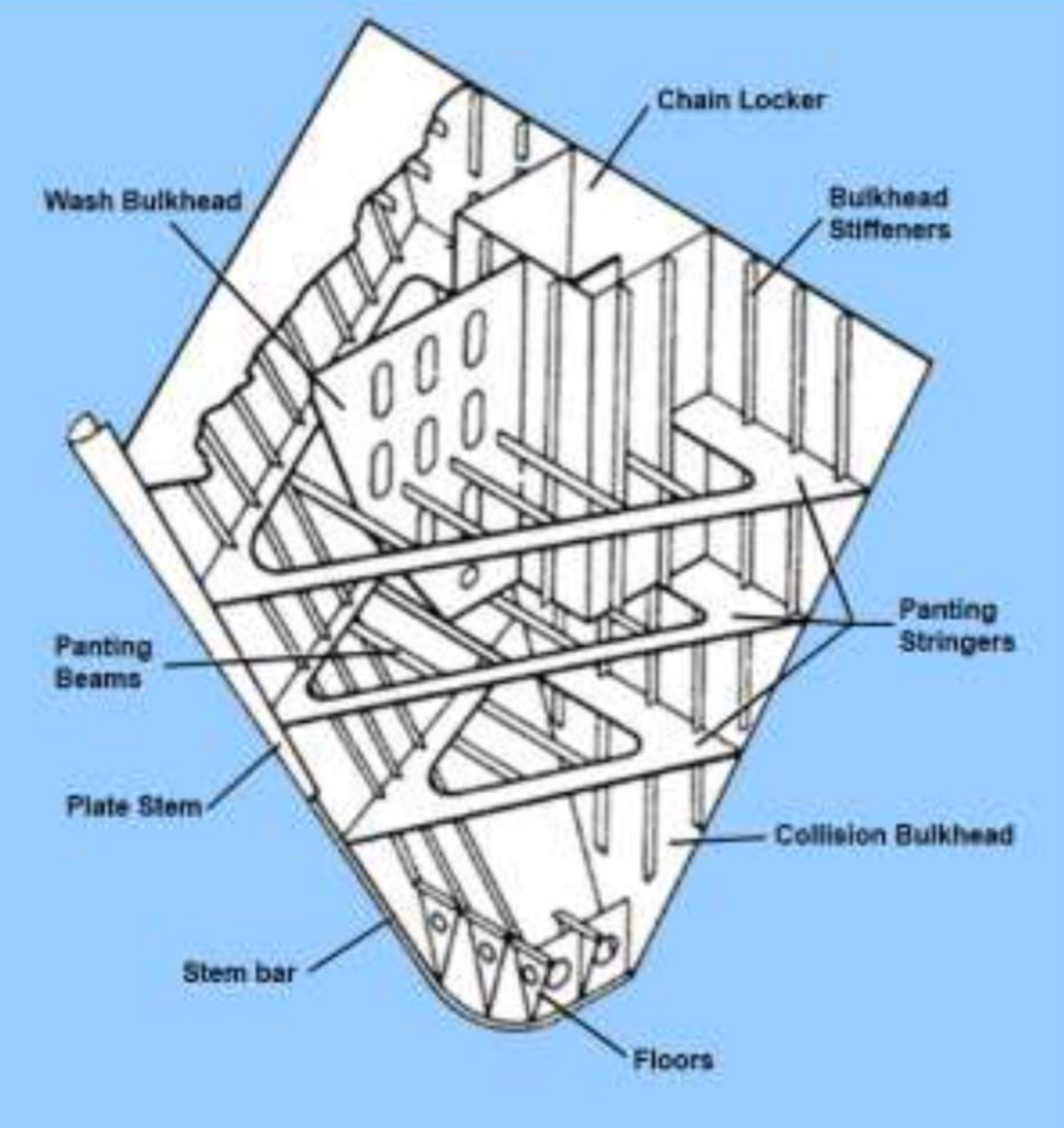
- Stiffening in the form of frames, breast hooks, wash plates, deep radius floors, pillars, panting stringers, panting beams, and a variety of stringers and girders. Their scantlings, material allowance and proper positioning dictate the "structural resilience" to all the localised loadings.
- Chain lockers
- Decks
- Bow — bulbous, clipper, X-bow and so on.
The principle of the arrangement. The designer's freedom at the fore end is not in whether to stiffen, but in where:
An essential feature of the fore arrangement are the deviation in scantlings and positions of the net panel-stiffening arrangement, in the light of its requisite strength to sustain these load-condition vagaries.
Why: as the load parameters are more pronounced in the fore part, and a stake of local as well as global stresses — especially panting and pounding — are highly unpredictable, the ship designer has to pay more attention to this part to make it more "fit". Furthermore, from the strength point of view, if the loading is hindered at this point, its effects on the remaining length of the ship become less domineering. The classification societies have prepared a consensus regarding the dimensional allowance that may be purported to these plate stiffening arrangements, for higher load-sustaining capacity.
That last sentence is the design argument for the whole part: the fore end is where the ship takes the sea's first hit, and everything aft of it is protected by how well the fore end takes that hit.
8.1.5 The specially applied stiffening measures
Taken one at a time, because each has its own duty.
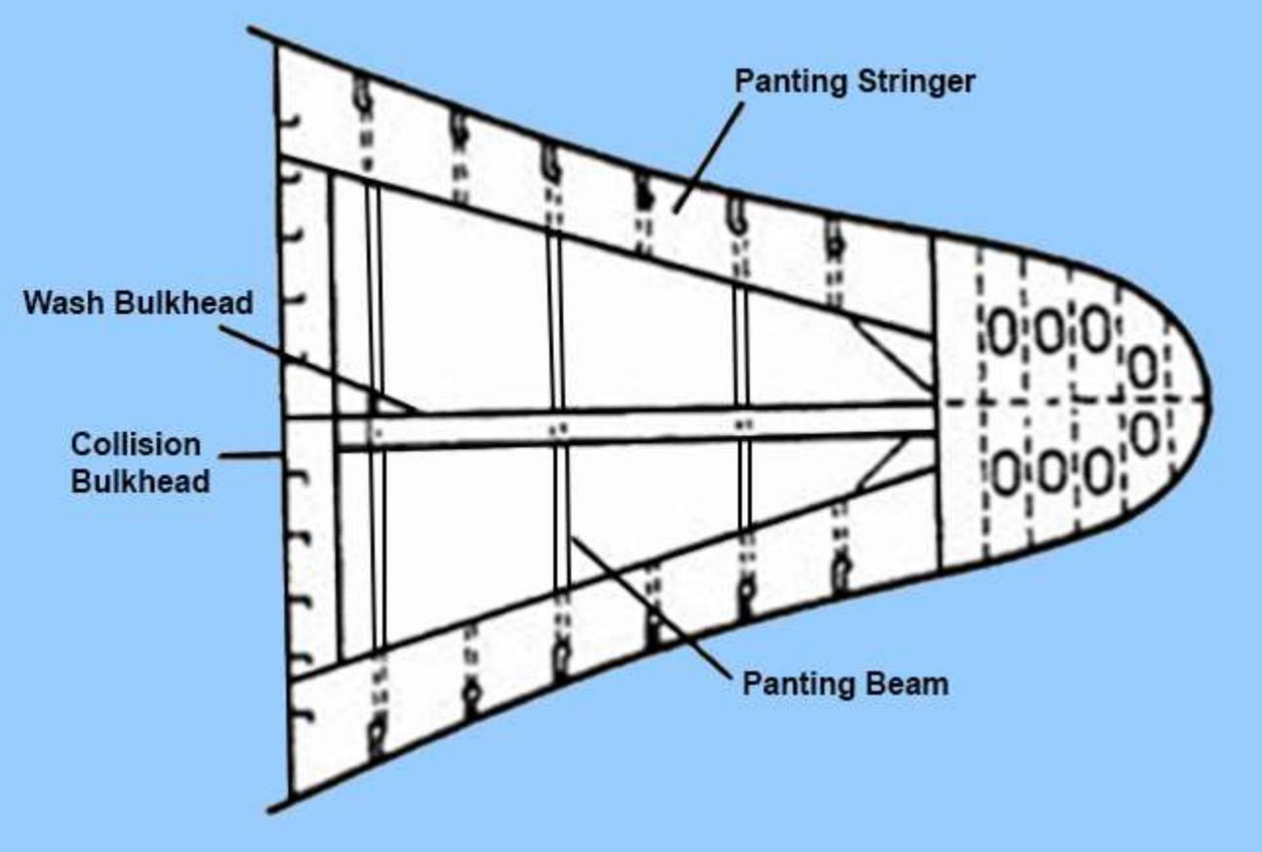
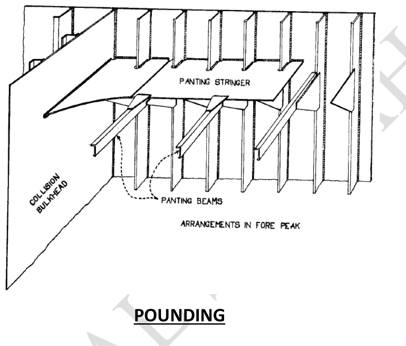
Panting stringers. Longitudinal stiffening members formed in a closed rounded-triangular shape (peak being the fore end) by the side stringers on both sides and the collision bulkhead at its end.
The description is geometric and it is worth drawing: the two side stringers converge towards the stem, and the collision bulkhead closes the base of the triangle. What has been built is a ring of stiffening around the fore peak tank, and it is closed because a ring is what resists a shell that wants to move in and out.
The perforated bulkhead at the centreline. A perforated bulkhead often exists at the centreline. Although its main function is dedicated to cargo storage and reduction of free surface effect, it adds to the longitudinal strength of the fore peak tank. Most of the time the angle pillars along with the panting beams are joined to the wash bulkhead, and they are very useful when the unsupported span of panting beams becomes large.
Perforated non-watertight flats. Sometimes, for fuller-form ships like bulk carriers, the fore part is stiffened by large perforated non-watertight flats to cater to enhanced transverse strength.
Breast hooks. Breast hooks stiffen the stem plate and behave as the support tip of the panting and side stringers. They also play the pivotal role of transverse strengthening of a large number of plates in the forward and side regions. However, the usability of breast hooks becomes pointless when there are tween decks.
Defined more briefly elsewhere: a breast hook is a triangular plate bracket joining structural members of the port and starboard sides at the stem.
That last clause about tween decks is the detail worth holding. A breast hook works by tying the port side to the starboard side at the stem, so it is only useful where there is a span to tie across. Fit a tween deck and the deck itself already does that job at each level, so the breast hook's transverse function is duplicated and it becomes pointless.
8.1.6 The full fore end stiffening set
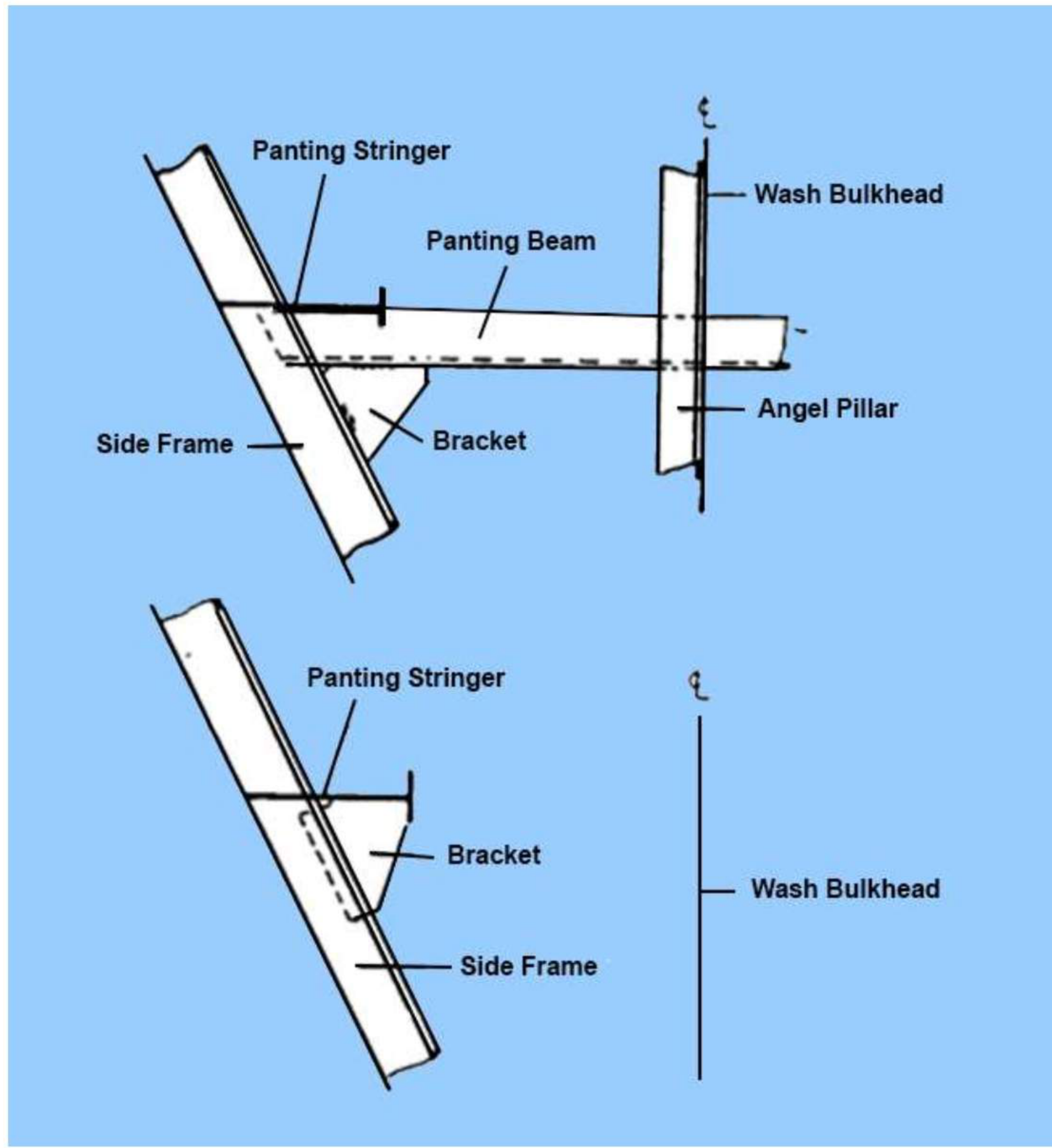
The transverse view assembles the whole arrangement, and the members in it are the ones to be able to name in a drawing:
| Member | Position and duty |
|---|---|
| Panting stringer | Horizontal, running fore and aft along the shell at intervals; the primary panting member |
| Panting beam | Transverse, at alternate frames below the lowest deck; stops the two sides moving independently |
| Wash bulkhead | At the centreline; reduces free surface, carries the pillars, supports long panting beams |
| Angle pillar | Between the panting beams and the wash bulkhead — the intermediate support the beams need |
| Side frame | The transverse framing of the shell itself, bracketed to the stringers |
| Bracket | The connection of the frames to the stringers and beams, where the load changes direction |
| Breast hook | Triangular, at the stem, tying port to starboard |
| Plate floor | At the bottom, forming the fore peak tank's lower boundary |
| Perforated flat | Where a full deck-level panel of transverse stiffening is needed, usually in fuller hulls |
8.1.7 Stiffening arrangements for hulls of higher Froude number
Although most of the measures above are sufficient to sustain high pounding loads, some extra modification ought to be made, especially with due respect to the bottom structures.
The forward bottom plating may be subject to buckling loads due to slamming / pounding. This effect is much more adverse in winter, and is the most pronounced in planing vessels — that is, having a higher Froude number. Thus while designing them, the stiffening arrangements are done in accordance with the speed-to-length relationships.
The burden of that is that the fore end scantlings are not a single fixed rule. They scale with how hard the ship drives into the sea, which is what the Froude number measures — the speed relative to the wave speed the hull length generates. A slow, full merchant hull and a fast, fine planing hull hit the same wave with entirely different energy, so they need different amounts of structure forward.
8.2 Panting and pounding arrangements
8.2.1 Panting and its resistance arrangements
The definition, in the form to quote:
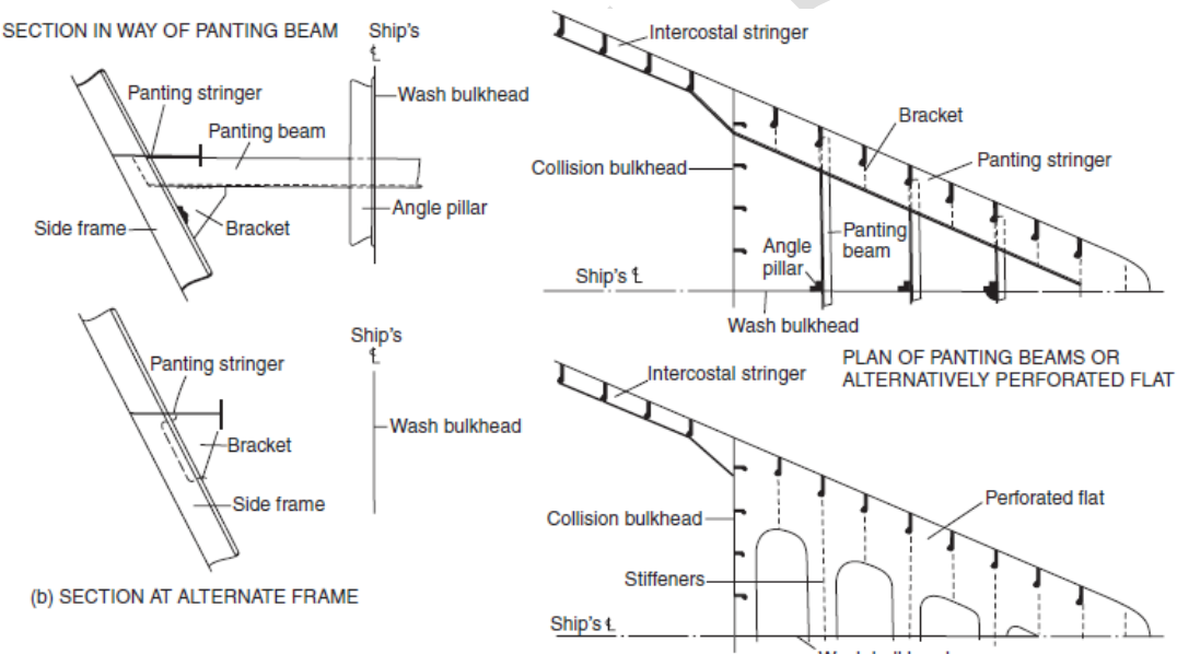
As the waves pass along the ship they cause fluctuations in water pressure which tend to create an in-and-out movement of the shell plating. The effect of this is found to be greatest at the ends of the ship, particularly at the fore end, where the shell is relatively flat. Such movements are termed panting, and, if unrestricted, could eventually lead to fatigue of the material, and must therefore be prevented. The structure at the ends of the ship is stiffened to prevent any undue movement of the shell.
The "relatively flat" clause is the mechanism of the fore end in three words. A shell that is curved resists a pressure change by membrane action — it arches. A shell that is flat has nothing but its own bending stiffness, so it deflects.
The extent. The structure of the ship is strengthened to resist the effects of panting from 15 per cent of the ship's length from forward to the stem, and aft of the after peak bulkhead.
The arrangement:
| Arrangement | Detail |
|---|---|
| Side stringers | Fitted to the shell at intervals of 2 m, below the lowest deck |
| Panting beams | Fitted forward of the collision bulkhead, below the lowest deck; connected to the beam knee; fitted on alternate frames |
| Beam spacing | Not more than 2 m apart vertically, and supported by pillars |
| Panting stringers | Laid on each beam |
| Perforated flats | Spaced not more than 2.5 m apart; perforations not less than 10 per cent of the total area |
| Wash bulkhead | A partial wash bulkhead at the centreline, supporting long panting beams |
8.2.2 Pounding and its resistance arrangements
The definition:
When a ship meets heavy weather and commences heaving and pitching, the rise of the fore end of the ship occasionally synchronises with the trough of a wave. The fore end then emerges from the water and re-enters with a tremendous slamming effect, known as pounding. While this does not occur with great regularity, it may nevertheless cause damage to the bottom of the ship forward. The shell plating must be stiffened to prevent buckling. Pounding also occurs aft in way of the cruiser stern, but the effects are not nearly as great.
The word synchronises is the operative one: it is a resonance condition, not a constant. And the failure mode is named — buckling, not rupture. That matches Part 6 §6.2.7 and Part 4 §4.2: the forward bottom is under compression as the hull hogs, and a thin plate in compression buckles.
The extent and the length threshold:
Pounding effect is expected in the bottom of the ship 30 per cent of ship length abaft the stem. So this 30 per cent area — the pounding region — is additionally strengthened in ships exceeding 65 m in length.
The arrangements, by framing system:
| Framing system | Requirement |
|---|---|
| Transversely framed | Plate floors fitted at every frame space, connected to the outer bottom plating by continuous weld. Longitudinal girders fitted 2.2 m apart, extending vertically from the shell to the tank top. Intermediate half-height girders fitted to the shell |
| Longitudinally framed | The spacing between longitudinals is reduced to 700 mm, and they are continued as far forward as practicable to the collision bulkhead. Transverse floors fitted at alternate frames. Side girders fitted not more than 2.1 m apart |
The comparison between the two columns is the answer to a question that is easy to get backwards. In a transversely framed bottom, the floors are the primary members, so they are doubled in frequency — every frame space instead of every three or four — and the girders stay where they are at 2.2 m. In a longitudinally framed bottom, the longitudinals are the primary members, so it is their spacing that is reduced, from the normal to 700 mm, while the floors stay at alternate frames and the girders tighten slightly to 2.1 m. Each system thickens the member that is already carrying the longitudinal bending.
Shell and double-bottom details in the pounding region: the four strakes of shell plating either side of the keel are generally increased in thickness in the pounding region; the cellular double bottom arrangement of the rest of the ship is discontinued in the fore peak tank; and the centre and side girders are extended forward for a few floors to resist distortion of the bottom due to slamming, and discontinued as the width of the bottom gets narrow. Panting stringers forward of the collision bulkhead are fitted not more than 2.0 m apart, bracketed to the shell frames, with panting beams on alternate frames under each stringer.
8.2.3 The two extents, side by side
The two local loadings are defined by different extents, and holding them apart is what stops the answer becoming a blur:
| Panting | Pounding | |
|---|---|---|
| Region | 15% of L from forward to the stem, and aft of the after peak bulkhead | 30% of L abaft the stem in the bottom (from 5% abaft the stem where the forward edge is stated) |
| Fails by | Fatigue of the material | Buckling of the bottom plating |
| Worst in | Fine-bowed ships (flat shell) | Full-bowed ships; light or ballast condition; winter; higher Froude number |
| Threshold | — | Ships exceeding 65 m in length |
| Primary members | Side stringers at 2 m, panting beams at alternate frames, perforated flats at 2.5 m, wash bulkhead | Floors, side girders and shell plating of the forward bottom |
Note where the two overlap. Both extend forward from the stem, but the pounding region is the bottom and the panting region is the shell. That is why the transverse drawing of the fore peak shows panting stringers along the sides and plate floors across the bottom of the same compartment, and why both sets of members appear in the one picture.
8.2.4 Deep horizontal stringers as additional stiffening
The deep horizontal stringer can provide additional stiffening to the shell plating if required.
The deep stringer is the heavy member of the same family as the panting stringer — it runs fore and aft along the shell, but its depth is considerably greater. It is provided where the ordinary stringers are found to be insufficient, and it therefore belongs to the high-load cases of §8.1.7 and to the fuller hulls. Part 10 takes up where deep stringers are fitted in general; at the fore end they are one more panel-breaking member in the panting arrangement.
8.3 Bow form
8.3.1 Stem construction
The stem is the front-most part of the boat or ship's bow, and it is the structural member that closes the shell forward, running from the keel to the deck and taking the first of everything the sea delivers. In the fore end arrangement drawing the stem appears in its two parts: the plate stem, which is the plating of the stem itself, and the stem bar, the solid bar at its forward edge that takes the wear and the impact.
The stem bar is the same idea as the bar keel of Part 6 §6.7.3 and the ground bar under the bilge keel of Part 6 §6.7.6: a renewable, replaceable solid member put where a ship meets something hard, so that the thing that gets worn away is not the shell. Part 1b gives the stem and the forward perpendicular as reference points; here it is the structure that actually takes the load.
8.3.2 Bow waves and their formation
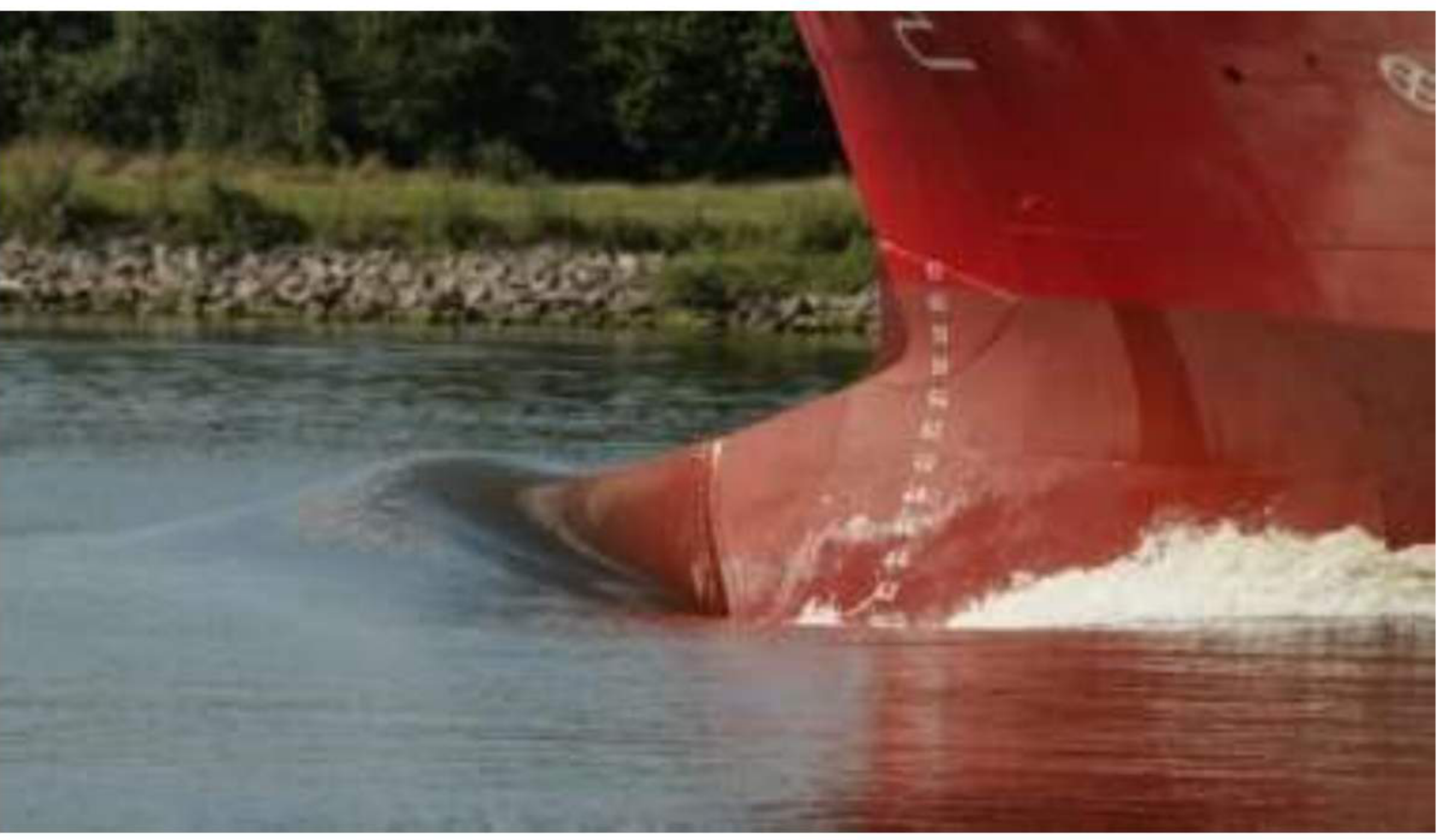
Why a bow wave forms. Consider a ship without a bulbous bow. As the ship moves forward, the water particles move towards the stern along the entire length of the ship. But the water particle which is incident right at the centreline of the stem has instantaneous velocity zero — that point is called the stagnation point, and the pressure at this point will be higher, which gives rise to the crest of a wave. This wave is called the bow wave. And, crucially: we are wasting a part of the engine power in generating this wave.
The stagnation point is the whole mechanism. At the very front of the stem the water is brought momentarily to rest against the hull, all of its kinetic energy becoming pressure; that pressure peak raises the free surface, and the raised surface is the bow wave. The energy in that wave came out of the engine, and it is never recovered — it is the wave-making component of resistance.
Where bow waves are prominent, and where they are not:
Wave making is a significant characteristic of finer hull forms. That is why you notice prominent Kelvin waveforms in cruise ships, liners, yachts and naval cruisers. If you notice a bulk carrier or an oil tanker (fuller hull forms), it is evident that these hull forms do not show prominent Kelvin wave patterns.
And the reason the fuller hull does not show them is not that it has less resistance:
Because the waterline width at the stem itself is so large — in other words, the discontinuity inflow is higher — that the pressure rises to a level such that the bow wave height exceeds the threshold up to which a wave holds its properties. In this case, the wave breaks right at the bow itself, even before it travels along the ship's length. So, are fuller hull forms more energy efficient in this respect? No. Do fuller hull forms have high wave-making resistance? No. Do fuller hull forms have high wave-breaking resistance? Yes. With this application, bulbs were also introduced in bulkers and tankers to reduce their wave-breaking resistance.
That three-question sequence is the sharpest thing on this subject, and it is worth answering it exactly as put. A full hull has not escaped the cost of the bow wave by being blunt — it has merely converted wave-making resistance into wave-breaking resistance. The energy is still spent; it is spent making white water at the stem instead of making a clean Kelvin pattern. That is why the bulb applies to full ships too, and why the benefit there is a different one.
8.3.3 Destructive interference and reduced wave-making
The design idea:
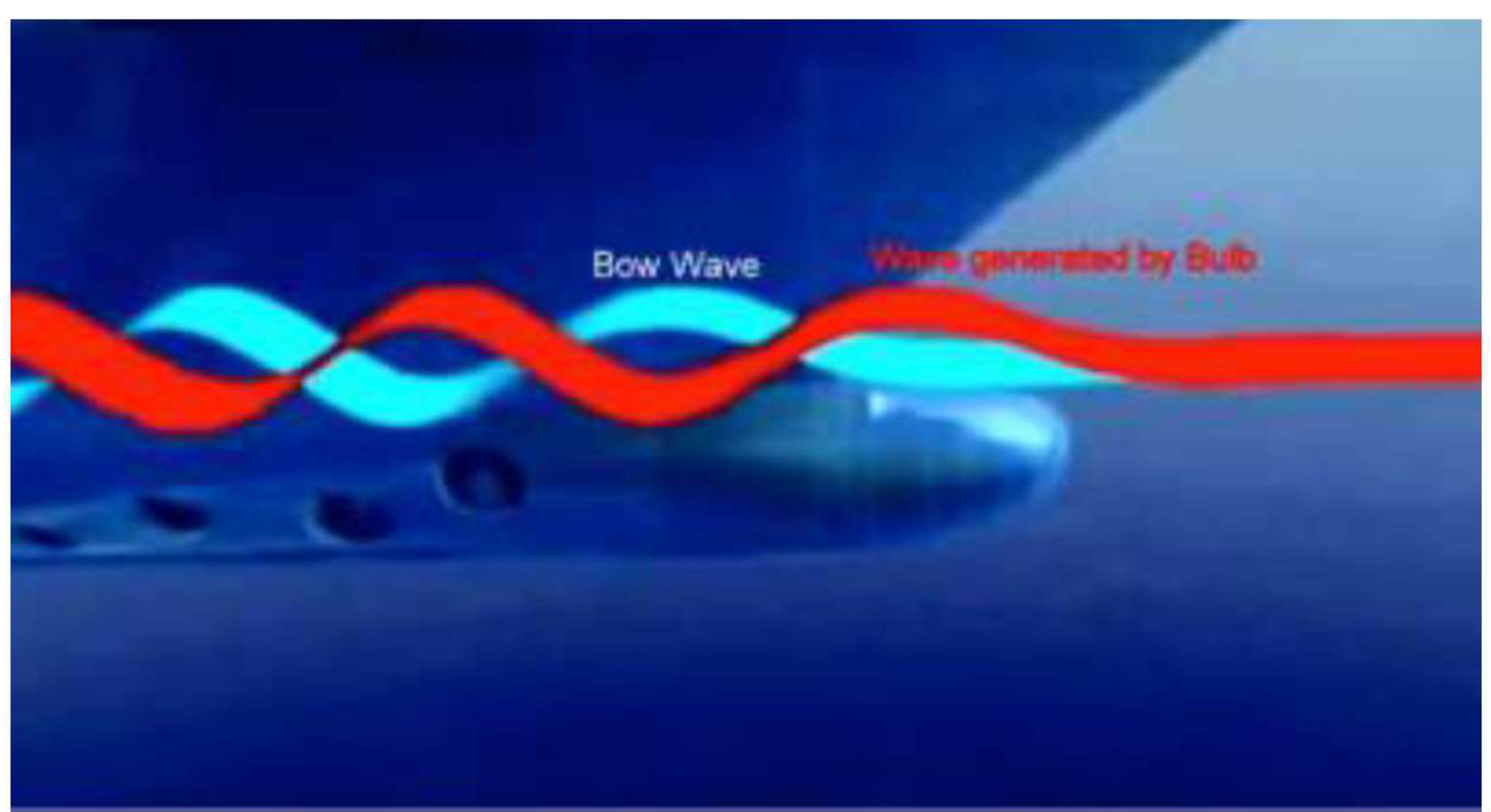
What if we can design the shape and position of the discontinuity in such a way that the bow wave and the wave created by the discontinuity result in a destructive interference? That is pretty much the principle behind the design of a bulbous bow. The destructive interference results in reduced wave-making of the ship, and which further reduces the wave-making drag of the hull form.
What the bulb is, and what it does:
A bulbous bow is an extension of the hull just below the load waterline. It is of bulb-like shape. The basic purpose is to create a low-pressure zone to reduce or eliminate the bow wave and reduce the resulting drag. A ship with a bulbous bow requires far less propulsive power and has considerably better resistance characteristics than the same ship without one. The principle of the bulbous bow is that it is sized, shaped and positioned so as to create a wave system at the bow which partially cancels out the ship's own bow wave system, so reducing wave-making resistance.
And in the shipping-practice form:
Location: just below the water line and in front of the ship's hull. Work: it reduces the hull wave-making resistance of a ship, which is the major residual resistance of a ship. When water is cut by the bulbous bow, two types of wave are generated. The primary wave, formed by the bow just in front of it, cuts the secondary wave formed by the ship's hull and reduces the drag. So hull wave-making resistance is reduced, so more efficient and lesser fuel oil consumption.
The chain, in one line:
What decides whether it works:
| Parameter | What it controls |
|---|---|
| Position of the bulb | Significantly affects the phase difference between the bow wave and the bulb wave |
| Volume of the bulb | A deciding factor of the amplitude of the resultant wave |
So the two things the designer is choosing are the phase and the amplitude. Position sets whether the two waves cancel or reinforce; volume sets how much cancellation there is to be had. Getting the position wrong does not merely fail to help — it can put the two waves in phase and make the resistance worse, which is the physical reason the bulb is always designed for a particular service speed and draught.
8.3.4 The other advantages of a bulb
The bulb was developed for wave-making resistance, but that is not all it has come to do:
| Advantage | How |
|---|---|
| Increased propulsion efficiency | Reduced wave-making resistance |
| Reduced fuel oil consumption, increased range | Follows from the efficiency gain |
| Increased ship speed | The same power gives more speed, or the same speed less power |
| Reduced pitching | The bulb is ballasted (see below), increasing the pitch period |
| Increased stability | The bulb's volume adds buoyancy low and forward |
| Increased buoyancy | Displacement of the bulb volume |
| Reduced drag | The destructive interference |
| Works as a "bumper" in the event of collision | The bulb is the first thing to meet an impact, forward of the shell proper |
| Allows a bow thruster at a foremost position, making it more efficient | The bulb provides the volume in which the athwartships tunnel can be housed forward |
| Extra protection against panting and pounding | The bulb's own structure stiffens the fore end |
The two unusual ones are worth explaining, because they are not obvious from the interference principle.
Reduced pitching, by increasing the pitch period:
Another advantage of the bulb is that it reduces the dynamic effects of the pitch motion of a ship. In most ships the interior of the bulb is used as a fore-peak ballast tank. In the case of high pitching, the forepeak tank is often ballasted to reduce the effect of pitching. Why? The time period of pitching is directly proportional to the longitudinal distance of weights from the LCG of the ship. When the fore peak is ballasted, it increases weight at a larger distance from the LCG of the ship (which in most ideal cases is abaft the midship). In other words, the pitch radius of gyration increases, therefore increasing the pitch period of the ship. Increased period of pitching results in less dynamic effects of pitch motion.
It is the same relationship as the roll period in Part 3 §3.8, applied to the other axis: period grows with radius of gyration, and a longer period means a slower, gentler motion. The bulb gives the ship a place to put ballast that is far from the LCG, which is exactly what lengthens the period.
Ice navigation and SONAR:
- In the case of ice navigation, the bulb allows broken ice to glide along the hull with its wet side against the hull. The wet side of the ice has a lower coefficient of friction, which reduces the overall drag on the ship.
- In naval ships that use high-frequency underwater acoustics like SONAR, bulbous bows act as protective housing, in addition to their positive effects on drag reduction.
8.3.5 Why a bulb is ineffective at low Froude number
The finding:
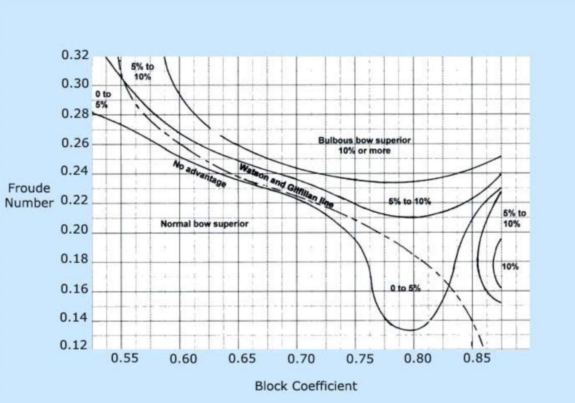
After repeated model testing procedures of a wide range of hull forms and bulb shapes, it has been found that bulbs are not efficient at all service speeds — relate it to Froude numbers. In very low Froude numbers, bulbous bows have been found to increase the drag.
Why:
Because a bulb is only effective when it makes its own wave, along with the bow wave. But at very low Froude numbers, wave-making hardly occurs. But the bulb, still being below the waterline, increases the total wetted surface area of the ship, therefore contributing to increasing its skin friction resistance.
This is the cleanest trade-off in the part, and it follows from the two components of resistance:
| High Froude number | Low Froude number | |
|---|---|---|
| Wave-making | Significant — the bulb has a wave to cancel | Hardly occurs — there is nothing to cancel |
| Wetted surface | The bulb's extra area is a small price | The bulb's extra area is the whole cost |
| Net effect of the bulb | Benefit | Increased drag |
The bulb pays for itself only where wave-making resistance is large enough that cancelling part of it exceeds the skin-friction penalty of the extra wetted surface. At low speed that condition never arises, so a bulb on a slow ship is pure loss. That is why the bulb is not fitted to every hull, and why the Froude-number/block-coefficient chart is drawn as a map of which bow is superior where rather than as a single recommendation.
8.3.6 Bulbous bow limitations
The published limitations of the bulb, gathered from the physics above:
- Ineffective at low Froude numbers — it increases drag below the speed at which wave-making becomes significant.
- Tuned to a particular condition — performance depends on the position (phase) and volume (amplitude) of the bulb, both set for a design speed and draught; off that condition the benefit diminishes.
- Adds wetted surface — a permanent skin-friction penalty against a speed-dependent benefit.
- Adds structure and weight forward — the bulb is a fabricated structure enclosing a tank, and it must itself resist panting, pounding and, on some ships, ice.
- Adds a projection from the hull — which is why its own structure is strengthened, and why the classification society rules for the fore end apply to it.
8.3.7 Bow flare and its contribution to slamming
Flare is the spreading out of the hull form from the centre vertical plane, usually in the fore body above the waterline. In Part 1 it is defined as the outward curvature of the shell at the forward end of the ship, with the purposes of increasing the reserve of buoyancy at the forward end to give better seaworthiness when pitching, and of dispersing water away from the ship when lightly pitching.
Structurally, flare is one of the three named forms of slamming — bow-flare slamming — and it is the one that strikes the flared shell above the waterline as the bow pitches down and the flare enters the water broadside-on. This is the connection between the three forms together: slamming can be mostly bow-flare slamming, stern slamming or bottom slamming.
The mechanism is worth stating as the reason flare is a trade rather than a pure benefit. Flare buys reserve buoyancy and a drier deck, which is why every ship has some. It also presents a large, broadly inclined surface to the water, and each impact of that surface sends a lateral and vertical shock into the shell and the deck structure — which is why the fore end of a flared ship needs the stiffening of §8.1.5, and why too much flare is as much a structural decision as a seakeeping one.
8.3.8 Bow form and rake
The bow designs in existence: the bulbous bow, a normal bow without a bulb, and other special bows.
The rake. A normal bow has developed from its predecessor, which was a vertical bow. The angle at which the ship's stem makes with the waterline is called the rake.
| Bow form | Character | Consequences |
|---|---|---|
| Plumb bow | A vertical, unraked bow having a straight edge | Maximum waterline besides an X-bow or inverted bow. This length of the waterline allows for a greater hull speed |
| Raked bow | Stem inclined to the waterline | Used in conjunction with flare; benefits below |
| Clipper bow | Traditionally the raked form | As for the raked bow |
| Spoon bow | Resembles a spoon, giving a concave appearance at the stem and deck line | These forms often have chining and curvature at the waterline, creating their characteristic wake pattern, which brings wave-making resistance into the picture |
What the rake buys:
- Bow rakes are used in conjunction with flares. Flaring has its own benefits, like keeping water off the decks, and also eases the pitching motions.
- Some raking also sets up what is called "crumple zones", allowing safety against collisions before the submerged portion comes in contact with it.
- Stability-wise, it raises the centre of buoyancy, which in turn increases the GM — one of the pillars of ship stability.
The crumple zone is the structural point and it is the same principle as the collision bulkhead of Part 7 §7.4: the raked, flared bow above the waterline is structure that is expected to be sacrificed in a collision before the watertight envelope below and behind it is reached. The bulb's "bumper" role in §8.3.4 is a variation on the same theme.
The stability effect is worth noting as well because it inverts the usual intuition about weight forward: rake raises the centre of buoyancy by shifting immersed volume, and since GM depends on the separation between B and G, a higher B raises the GM. That improvement comes without adding ballast.
8.3.9 Forecastle
The forecastle is the forward raised deck of the ship, and in the fore end arrangement drawing it appears as the fo'c'sle deck above the upper deck, carrying the windlass and the chain locker access.
The forecastle is a structural and operational feature rather than only a space:
- It is a raised deck at the fore end, which increases the freeboard and hence the reserve buoyancy where the ship is most likely to be immersed by pitching — the same duty as sheer, and often provided instead of sheer on modern ships.
- It houses the ground tackle: the windlass, the chain stoppers, the spurling pipes, and in many arrangements the chain locker itself, which is fitted between the upper and second decks, below the second deck, or in the forecastle.
- Where the chain locker is fitted in the forecastle, the bulkhead may be used to support the windlass.
8.3.10 Freeing port area and well deck length
Freeing ports are an opening in the lower portion of a bulwark, which allows deck water to drain directly overboard. Some freeing ports have hinged gates that allow water to drain overboard but that swing shut to prevent seawater flowing inboard.
The rules for their area and arrangement:
- The area of the freeing port on each side depends on the length of the well deck.
- The lower edge of the port must be as near to the deck as possible.
- The openings are to be protected by rails spaced approximately 230 mm apart.
- When hinged flaps are fitted, the hinges must be of non-corrodible material.
How a freeing port differs from a scupper:
| Freeing port | Scupper | |
|---|---|---|
| Position | An opening in the lower portion of a bulwark | A system of gravity deck drains and connected piping |
| Discharge | Directly overboard through the bulwark | From scupper wells to the side shell of the ship, or to the bilge system |
| Construction | An aperture, sometimes with a hinged gate | Pipes and a well |
The well deck is the deck area enclosed between two raised decks — typically between the forecastle and the bridge — from which water cannot run off freely along the ship's length, because the raised decks at either end block it. That is the reason the freeing-port area scales with the well deck's length: the longer the well, the more deck water it collects and the more aperture is needed to clear it.
The 230 mm rail spacing and the hinge material are the two small details that show what the requirement is guarding against. The rails stop a person going overboard through the opening; the non-corrodible hinges stop the hinged gate from seizing open, which would leave an unguarded hole in the bulwark exposed to any sea that comes aboard.
8.4 Ground tackle and the fore end
8.4.1 Chain locker — location and construction
Location:
- Fitted between the upper and second deck, below the second deck, or in the forecastle.
- Usually forward of the collision bulkhead.
- It is not carried out to the ship side.
- It must have sufficient volume to allow adequate head room when the anchors are in the stowed position.
Connection and construction:
| Item | Detail |
|---|---|
| Spurling pipe (chain pipe) | Connects the chain locker to the deck |
| Hawse pipe | Runs from the deck to the hull of the ship. When the anchor chain is recovered from the sea, mud will stick to it, so a fire hose line is fitted in the hawse pipe to clean the anchor chain |
| Canvas sleeve | At the top of the chain or spurling pipe, to keep water from entering the chain locker |
| Drainage | Any fluid accumulated in the chain locker is removed by eductor for direct discharge overboard |
| Chain stopper | Fastened with a hinged lever, used to lock the chain in any desired position, and it releases the load from the windlass either when the anchor is out or stowed |
| Cable lifter | Arranged over the spurling pipe, to ensure a direct lead for the cable onto the locker |
| Bitter end | The end of a chain secured in the chain locker, attached to the hull by a quick-release mechanism known as the bitter end |
| Stiffeners | Existing stiffeners are fitted to the fore side of the collision bulkhead, with two similar sections fitted horizontally back to back, riveted to the bulkhead and welded to the stiffeners |
| Stiffener position | Fitted outside the locker, to prevent damage from the chains |
| Securing the end link | A space is allowed between the horizontal bars to allow the end link of the cable to slide in and be secured by a bolt |
| Centreline division | Fitted to separate the two chains, port and starboard |
| Locker in the forecastle | If the locker is fitted in the forecastle, the bulkhead may be used to support the windlass |
| Access | A hinged door is fitted in the forward bulkhead, giving access to the locker from the store space |
| False floor | The locker is fitted with a false floor to allow drainage of water and mud, with the help of a drain plug in the forward bulkhead |
Why the locker is forward of the collision bulkhead, and why it is not carried out to the ship's side. The locker must be as far forward as possible so that the weight of the cable lands where the cable hangs, keeping the lead from the windlass to the hawse pipe straight. And it must be inboard of the shell because a grounding or a light impact at the bow that opened a shell plate into a chain locker would put the collision bulkhead's protection to no purpose — the locker must survive the same damage the bulkhead is designed to contain.
The bitter end is the detail that turns the locker from a store into a safety item: it is an attachment the crew can release from inside the ship, so that if the cable must be slipped — in an emergency, or because the anchor is fouled beyond recovery — the whole cable can be let go from a point inside the hull rather than cut at the windlass.
8.4.2 Chain locker inspection
Chain locker is an enclosed space, so an enclosed space permit is to be obtained and complied with.
The inspection, in order:
- Drop anchor and enter chain locker.
- Clean chain locker, remove mud and silt deposit.
- Check mud box pumping system.
- After cleaning, check for signs of corrosion.
- Check the bitter end of the chain for signs of damage.
- Repaint chain locker with protective coating.
Two entries in that list carry more weight than the others. The permit comes first because a chain locker is a closed, poorly ventilated, unlit space reached through a small hatch — it is a classic enclosed space entry. And the anchor is dropped before the locker is entered because with the cable stowed the locker is full of chain and there is no room to work; the chain has to be paid out to expose the space at all. The bitter end check then follows directly from §8.4.1: it is the one part of the ground tackle that is never inspected from the deck, and it is the part the ship depends on if the cable ever has to be released.
8.4.3 Hawse pipe and spurling pipe
Spurling pipe:
A steel pipe or tube through which an anchor chain passes to the chain locker below the forecastle deck of a ship.
Hawse pipe:
A pipe which guides the chain from deck level to outside the shell plating. The hawse pipe should be constructed to a size large enough to accommodate the smooth running of the chain and to provide secure stowage of the anchor, permitting it to drop freely when released without jamming or risking damage to the hull structure.
The two pipes, compared:
| Spurling pipe | Hawse pipe | |
|---|---|---|
| Runs from | Deck, down into the chain locker | Deck level, out through the shell |
| Carries | The chain from the windlass to the locker | The chain from the deck to the water |
| Other names | Chain pipe | — |
| Fittings | Canvas sleeve at the top to keep water out of the locker | Fire hose line to wash the mud off the chain as it comes inboard |
The two names are easy to swap and the direction of each is the way to keep them apart: the spurling pipe spurts the chain down into the locker, the hawse pipe takes it out of the ship through the hawse. The canvas sleeve and the washing line are each fitted to the one that needs them — water must be kept out of the locker, and mud must be washed off the chain before it gets there.
8.4.4 Windlass
A windlass is a machine used for hoisting or lowering the anchor.
The retrieval is powered from the same place as the rest: the ship retrieves the anchor by hoisting the chain with an anchor windlass, which has a great deal of torque. The chain stopper in §8.4.1 exists precisely so that this load is taken off the windlass once the anchor is secured — the windlass hoists, the stopper holds.
8.4.5 Devil's claw
A devil's claw is a stretching screw with two heavy hooks or claws. It is used to secure the anchor in the hawse pipe.
The name describes the device exactly: a turnbuckle with a hook at each end. One claw goes into the anchor's shackle or the cable, the other onto a lug or a deck fitting, and the screw is tightened to pull the anchor hard up into its hawse pipe. The purpose is stowage at sea: an anchor left to swing in its pipe would work against the structure at every pitch, so it is pulled up tight and held.
8.4.6 How an anchor holds the ship
The force is mostly the cable, not the anchor:
The primary force holding an anchored ship in place is the weight of the chain lying on the bottom and its friction with the bottom of the sea. The anchor does help, as the flukes are designed to dig into the bottom as well. When properly anchoring a ship, the amount of anchor chain paid out is 5 to 7 times the depth of the water, as a rule of thumb. The type of bottom is a contributing factor, with mud being the best holding and rock being the worst. The ship retrieves the anchor by hoisting the chain with an anchor windlass, which has a great deal of torque.
That first sentence is the one that is usually answered wrongly. The anchor's job is to be a point of attachment; the holding force is the catenary of chain lying along the seabed, whose weight and friction absorb the pull. This is why the scope ratio of 5 to 7 times the depth matters: short scope lifts the chain off the bottom and puts the whole load onto the anchor alone, which is also why the holding is a matter of the seabed material — mud best, rock worst — since it is the chain's friction with the bottom that is doing the work.
8.4.7 How the anchor cable is attached to the ship
Anchor is attached to the ship by the bitter end in the chain locker.
One line, and it is the answer to a question that expects exactly this. The chain is not shackled to the windlass, to a deck fitting or to the hawse pipe; the ship's end of the cable is the bitter end, secured inside the chain locker by the quick-release mechanism of §8.4.1. Everything between the bitter end and the anchor is the cable, and everything the ship feels through the cable arrives at that one attachment.
8.4.8 Material of an anchor
Material of anchor: galvanised steel.
The galvanising is the part worth noting: the anchor is immersed continuously, is dragged through sand and mud that removes whatever coating it has, and is the most heavily worked piece of ground tackle on the ship. It is the same argument as the stem bar in §8.3.1 and the ground bar under the bilge keel — a sacrificial member at the point of contact with the seabed.
8.4.9 Gypsies and wildcats on the windlass
The chain-handling wheel on a windlass is termed a "gypsy" (in the United Kingdom) or a "wildcat" (in North America).
The same answer gives the rest of the windlass terminology, and it is worth having together:
| Part | Definition |
|---|---|
| Gypsy / wildcat | The chain-handling wheel on the windlass |
| Warping head | The line-handling wheel |
So the windlass carries two kinds of wheel, and they are not interchangeable: a gypsy or wildcat is whetted — its rim is shaped with pockets to take the links of the chain and hold them without slipping, which is why it is named after a toothed animal. A warping head is smooth, because it is for wires and ropes that are taken round it by friction. The same distinction runs through Part 8's ground tackle: chain is driven positively, line is held by friction.
8.5 Bow thruster and fore peak
8.5.1 Bow thruster — position and function
Position:
Bow thrusters are manoeuvring devices fitted in an athwartship tunnel near to the bow and aft of the collision bulkhead. They give additional manoeuvring ability.
Function:
- Many ships are fitted with bow thrust units to improve their manoeuvrability.
- They are an obvious feature in ships working within, or constantly in and out of, harbour, where close control is obtained without the use of tugs.
- They have also proved to be of considerable benefit to larger vessels such as oil tankers and bulk carriers, where the tug requirement has been reduced.
Construction:
- In all cases the necessity to penetrate the hull forward causes an increase in ship resistance and hence in fuel costs, although the increase is small.
- A popular arrangement is to have a cylindrical duct passing through the ship from side to side, in which is fitted an impeller which can produce a thrust to port or to starboard.
- The complete duct must lie below the waterline at all draughts, the impeller acting best when subject to a reasonable head of water, and thus reducing the possibility of cavitation.
- The impeller may be of fixed pitch with a variable-speed motor which is reversible or has reverse gearing. Alternatively a controllable-pitch impeller may be used, having a constant-speed drive.
- Power may be provided by an electric motor, a diesel engine or a hydraulic motor.
Why it sits aft of the collision bulkhead. This is the question the position statement is answering, and the reason is Part 7 §7.4.3. The collision bulkhead's watertightness rule bans doors, manholes, access hatches, ventilation ducts or any other openings on it below the bulkhead deck, with only one carefully controlled piercing allowed for the forepeak ballast pipe. A bow thruster tunnel is a direct path from one side of the ship to the other, and its machinery must be reachable for maintenance. Putting the tunnel aft of the bulkhead keeps it inside the protected part of the ship, leaves the one permitted piercing in the bulkhead for the ballast pipe alone, and lets the duct be inspected and worked on without breaking the fore peak's integrity.
The depth requirement is the other constraint: the duct must be below the waterline at all draughts, including the lightest condition the ship will ever be in. That is why the tunnel sits low and forward, where the hull is deepest in the ballast condition.
The bulb connection is worth noting: the bulbous bow allows the installation of the bow thruster at a foremost position, making it more efficient. The bulb provides the volume, forward and low, in which a tunnel can be placed further forward than the hull form alone would allow — and the further forward the thruster, the greater its turning moment about the ship's pivot point.
8.5.2 Fore peak tank
The fore peak tank, as the name suggests, forms the foremost watertight tank, principally used for ballasting.
It is the compartment bounded by the collision bulkhead aft, the shell plating forward, the stem at its point, and the bottom structure below. It is the after boundary of the whole fore end structure: everything in §8.1 is arranged around it, and the collision bulkhead is its after wall.
Why it does more than ballast:
Fore peak tank, as the name suggests, forms the foremost watertight tank principally used for ballasting. But more than that, it serves a range of other purposes.
The others, gathered from the part as a whole:
| Purpose | Detail |
|---|---|
| Ballast | The principal use; fills the fore end to trim the ship by the head or to increase draught forward |
| Reducing pitching | Ballasting the fore peak tank increases the pitch period by increasing the pitch radius of gyration — the mechanism of §8.3.4 |
| Bulb tank | In ships with a bulbous bow, the interior of the bulb is used as a fore-peak ballast tank |
| Structural stiffening | The tank's own boundaries — panting stringers, panting beams, angle pillars, breast hooks, perforated flats and the centreline wash bulkhead — are what resist panting and pounding |
| Chain locker location | The chain lockers are usually fitted at the aft portion of the fore peak, at a higher level; the collision bulkhead forms the aftermost portion of the fore peak tank |
| Bow thruster housing | The forward part of the fore peak is where the thruster tunnel sits |
The chambers within it are bounded by members that also stiffen it, and the fore peak stringers are numbered from the bottom up — the transverse sections show stringers No. 1 to No. 4, the crown of the fore peak tank, transverse web, W.T. flat, pillars, deck girder and breast hooks. That is the whole fore end arrangement seen in section: the tank is not a void with stiffeners around it, the stiffeners form it, and its shape — narrowing forward and upward — is the shape the panting and pounding loads dictated.
The chain locker within the fore peak:
Collision bulkhead forms the aftermost portion of the fore peak tank. Usually port and starboard chain lockers are fitted at the aft portion and at a higher level. Anchor chains are stowed here and their bitter ends are secured at the chain locker bulkhead which can be released in case of emergency. They must be marked properly.
That "released in case of emergency" is the bitter end of §8.4.1 in its operational context, and the instruction to mark the bitter end properly is what makes the release possible: a cable that has to be slipped in an emergency is slipped in the dark, in a hurry, and the connecting link has to be identifiable by hand.
8.6 Summary — what the fore end has to answer
| Load | Fails by | Where it acts | What answers it |
|---|---|---|---|
| Panting | Fatigue | Shell over 15% of L from forward, and aft of the after peak | Side stringers at 2 m, panting beams at alternate frames, panting stringers on each beam, perforated flats at 2.5 m, centreline wash bulkhead, pillars |
| Pounding | Buckling | Bottom over 30% of L abaft the stem, ships over 65 m | Plate floors at every frame (transverse), longitudinals at 700 mm (longitudinal), side girders at 2.2 / 2.1 m, thickened shell strakes |
| Green water / wave slap | Structural damage to the deck | Exposed weather deck forward | Deck strengthening — more than the inner hull arrangements |
| Bow-flare slamming | Local shell and frame damage | Flared shell above the waterline | Flare plating and the framing behind it |
| Whipping | Fatigue and excess girder bending moment | The whole hull girder, excited at the bow | Control of slamming at the fore end before it can propagate |
| Impact from collision | Shell rupture, flooding | The bow forward of the collision bulkhead | Collision bulkhead at 5–8% of L (Part 7); crumple zones in the raked, flared bow; the bulb as a bumper |