
Decks, Openings and Watertight Closing Appliances
Every hole cut through the deck is a hole in the watertight envelope — how hatch covers, doors, ports and freeing ports close it again, and how each closure is proved.
Key Principles at a Glance 8 points
- A deck beam bracketed to the side frame at each end is a tie across the ship, and the closed ring it forms with the sides and bottom is what resists racking.
- A hatch coaming raises the hatch opening above the deck so that the cover seats above the level of water that will lie on the deck.
- Hatch cover weathertightness is proved by a hose test, an ultrasonic test, or a chalk test for compression of the packing.
- Watertight doors in a watertight bulkhead are sliding and positive closing, or hinged where they stand more than 2.2 m above the waterline; they are proved by a pressure tank test or a hose at 2 bar from 1.5 m.
- A weathertight door keeps out water that may lie on the deck and is proved from the outside; a watertight door keeps out the sea and is proved from the inside.
- Deadlights are hinged steel covers over a port or scuttle, and the rubber packing is inspected for cracks and fissures because it is the whole seal.
- Freeing ports drain the bulwark, and their gates must move freely — a seized shutter turns a bulwark into a tank that holds water on deck.
- The conditions of assignment of freeboard are the structural conditions a ship must meet to be given her freeboard at all; closing appliances are the largest part of them.
10.1 Deck structure
Everything cut through the deck is a hole in the watertight envelope. This part is about how the holes are closed and how the closures are proved. Part 7 divided the ship with bulkheads; this part is where those divisions are deliberately breached — for cargo, for access, for ventilation and for drainage — and where each breach has to be answered.
10.1.1 Deck beams
A deck beam is a transverse member running across the ship under a deck, supporting the deck plating and holding the two sides of the ship together at that level.
Its connection at each end is the part that matters:
A bracket between the deck beam and the side frame, together with a bracket between the side frame and the tank top, forms the standard end connection.
That pair of brackets is the same detail as the beam knee of Part 4 §4.3.2, and it is doing the same duty: it is the member that closes the corner of the picture frame and resists racking. A deck beam bracketed to the side frame at each end is a tie across the ship; the deck, the two sides and the bottom then form a closed ring at that station, and the ring is what stops the section folding sideways when the ship rolls.
10.1.2 Half beams
Transverse beams which are cut at the hatch side coamings are termed half beams.
The definition is entirely geometric and it explains itself: a deck beam normally runs right across the ship, but where a hatch opening interrupts it the beam can no longer be continuous. The length of beam on each side of the hatch is the half beam. It runs from the side frame to the hatch side coaming, and that is why the coaming in §10.1.3 is a structural member rather than merely a raised lip around a hole.
10.1.3 Hatch side coaming and its structural role
The vertical plating bounding a hatch, for the purpose of stiffening the edges of the opening and resisting entry of water to the ship's hull.
There are three duties in that one sentence and they are worth separating, because the coaming is doing all three at once:
| Duty | How |
|---|---|
| Stiffen the edges of the opening | The coaming is the support at the inboard end of the half beams of §10.1.2 |
| Resist entry of water | It is raised above the deck, so water on deck has to climb it to get into the hold |
| Support the hatch cover | It is the seating face against which the cover's packing is compressed |
Its scantlings and dimensions in the general arrangement are given in Part 10 §10.2.2.
10.1.4 Collar plate at the hatch corner
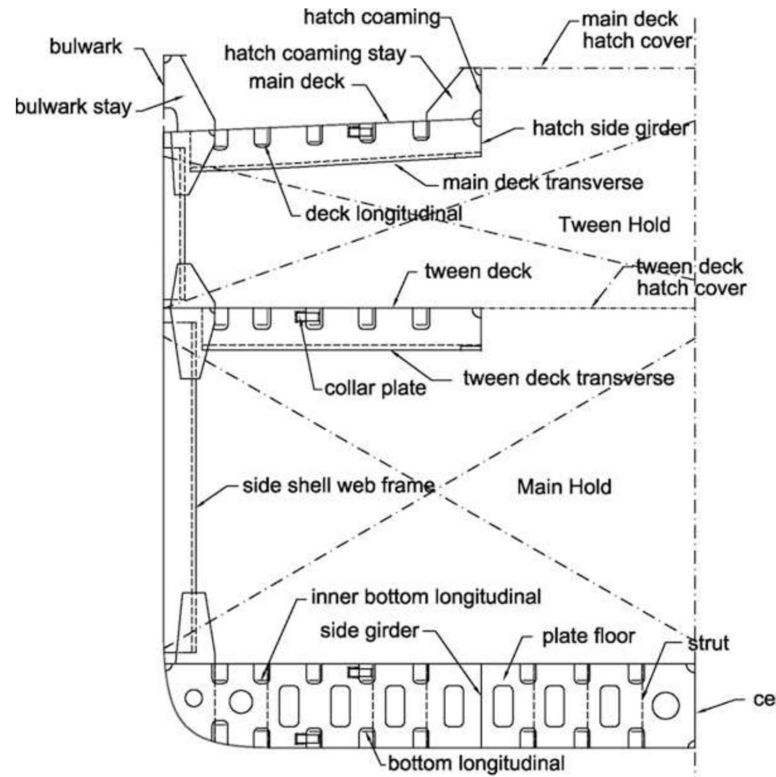
The collar plate appears in the midship sections of the general cargo carrier and the bulk carrier, drawn at the hatch corner where the hatch side coaming meets the deck.
The corner is the point of the whole arrangement that has to be looked at, because a rectangular opening in a deck creates four re-entrant corners, and a re-entrant corner is a stress concentration in a plate that is being worked by the longitudinal bending of Part 4. The collar plate is the local thickening — a doubler plate fitted at the corner — that carries the concentrated stress out into the surrounding deck plating rather than letting it start a crack at the corner itself.
It is the same idea as the doubling plate under the rudder carrier bearing (Part 9b §9b.2.12) and the doubling plate around the stern tube (Part 7 §7.4.5): where a structure is interrupted, or where a load is concentrated into a small area, the local material is increased rather than the whole member being made heavier.
10.1.5 Tween deck transverse framing
The tween deck is the deck between the main deck and the tank top, provided for facilitating cargo segregation and stowage.
The framing arrangement, as the general cargo carrier's midship section states it:
These vessels are of single skin type with double bottom, and generally have at least one tween deck … Decks and double bottom are longitudinally stiffened, whereas the side shells are transversely stiffened.
That is the compact answer to the framing question for a general cargo ship, and the reasoning is the one established in Part 6 §6.1.3. In a general cargo ship of moderate length the side shell is carrying local water pressure and needs only transverse frames; the decks and the double bottom are the members doing the work of the hull girder's flanges, and they are therefore stiffened longitudinally. The ship is a hybrid, and the hybrid is deliberate — each surface gets the framing its own duty requires.
The same section shows what goes into a tween deck: tween deck transverse members, hatch side girder, main deck transverse, deck longitudinal, side shell web frame, tween deck hatch cover, and at the hatch, the collar plate.
10.2 Hatch covers
10.2.1 Hatch cover and hatch coaming explained
The function of a hatch cover:
- Cargo holds are fitted with hatch covers to prevent the contact of cargo with the outer atmosphere — air, moisture, weather and water — and to avoid cargo getting wet.
- Another important function of a hatch cover is to maintain the watertight integrity of the ship at all sea-going conditions, by not allowing any ingress of water inside the cargo hold and disrupting the stability of the ship.
- Large hatches must be fitted in the decks of dry cargo ships to facilitate loading and discharging of cargo.
So the hatch cover is doing two jobs that are normally separated elsewhere in the ship: it is a cargo protection device and it is part of the watertight envelope. The second is the one that puts it in this part, and the phrase "disrupting the stability of the ship" is the reason — a hatch cover is a large area of the deck's watertight boundary, and any water that gets past it arrives high up and off the centreline, which is the worst place for it to arrive.
Why a coaming at all:
The hatches are framed by means of hatch coamings, which are vertical webs forming deep stiffeners. The heights of the coamings are governed by the International Load Line Rules.
| Position | Minimum coaming height |
|---|---|
| On weather decks | At least 600 mm at the fore end, and either 450 mm or 600 mm aft, depending upon the draught of the ship |
| Inside superstructures and on lower decks | No particular height specified |
And the rail requirement that follows from it:
It is necessary, for safety considerations, to fit some form of rail around any deck opening to a height of 800 mm. It is usual, therefore, at the weather deck, to extend the coaming to a height of 800 mm.
And the construction of that taller coaming:
- The weather deck hatch coamings must be 11 mm thick, and must be stiffened by a moulding at the top edge.
- Where the height of the coaming is 600 mm or more, a horizontal bulb angle or bulb plate is fitted to stiffen the coaming, which has additional support in the form of stays fitted at intervals of 3 m.
There are three heights in play and they should be kept apart, because the question is usually asked as "how high is a coaming" and the answer depends on which requirement is being satisfied:
| Height | What sets it |
|---|---|
| 450 mm or 600 mm | Load Line Rules — watertightness, aft, depending on draught |
| 600 mm | Load Line Rules — watertightness, at the fore end; also the threshold at which the bulb stiffener and 3 m stays become necessary |
| 800 mm | Crew safety — the height of the rail a person cannot fall over |
The 800 mm is not a load line requirement at all; it is a safety rail height, and the ship gets it by extending the coaming rather than by adding a separate rail, because a coaming already that tall is a rail.
10.2.2 Hatch sizes and their reasons
- It is usual to provide one hatch per hold or tween deck, although in ships having large holds, two hatches are sometimes arranged.
- The length and width of the hatch depend largely upon the size of the ship and the type of cargo likely to be carried.
- General cargo ships have hatches which will allow cargoes such as timber, cars, locomotives and crates of machinery to be loaded.
- A cargo tramp of about 10 000 tonnes deadweight may have five hatches, each 10 m long and 7 m wide, although one hatch, usually No. 2 hold, is often increased in length.
- Large hatches also allow easy handling of cargoes. Bulk carriers have long, wide hatches to allow the cargo to fill the extremities of the compartment without requiring trimming manually.
The general cargo carrier follows the same rule from the other direction:
Each hold is provided with one hatch opening, having hatch width somewhat less than half the deck width. For improving cargo loading and unloading, there can be multiple hatch openings in each hold. However, this adds to the production cost of the ship.
The "somewhat less than half the deck width" figure is the one that connects this section back to §10.1.2. A hatch of half the deck width leaves two half beams each of roughly a quarter of the ship's breadth — long enough to be a real structural span, and that is why the coaming they land on must be a deep stiffener and not a raised lip.
10.2.3 Maintenance of hatch covers
The materials:
- Hatch covers of cargo holds are generally made from lightweight steel or high tensile steel.
- They are fitted over a steel bar of the hold with a rubber packing inserted in between them to avoid water ingress.
The routine maintenance to be performed by a qualified officer:
| Check | Detail |
|---|---|
| Examination of the hatch cover | and hatch beams for corrosion, cracks and material failure |
| Cleats | Keep in operational condition at all times |
| Hauling wire, rollers, chains and wedges | In operational condition at all times |
| Cleanliness | Keep hatch cover tops and all drainage holes clear |
| Gaskets | Look for any broken or missing gasket and replace it immediately. The length of a renewed gasket must be a minimum of 1 m |
| Steel-to-steel | Before renewing a rubber gasket, check and rectify any steel-to-steel fault |
| Gasket type | Gasket rubber to be of a type approved by class |
| Greasing | Grease all the moving parts |
| Hydraulics | Check for any hydraulic system leakage if the cover is oil operated, and oil test to be performed for the hydraulic system |
| After repair | Call the surveyor after any major repair in the cover and its concerned parts |
Two of those entries carry more than their length suggests.
The one metre minimum length for a renewed gasket is a rule about joints, not about gaskets. A joined gasket has two ends meeting somewhere, and every joint is a potential leak path. Setting a minimum length for a replacement length of gasket reduces the number of joints over a given perimeter — and it prevents the practice of patching a small length in, which would add two joints to fix a damaged section.
Rectify the steel-to-steel fault before renewing the gasket is the rule that stops the gasket being wasted. If two steel faces are in hard contact somewhere along the seating, that contact will crush or cut the new gasket at the same point the old one failed. Replacing the gasket without dressing the steel reproduces the failure.
10.2.4 Testing of hatch covers — the three methods
After the maintenance procedure, it is advised to test the watertight integrity of the hatch cover by different methods. The three methods to check the watertightness of hold covers are.
10.2.4.1 Hose water test
In this test, a water spray from a nozzle of 12 mm diameter is sprayed over the joint of hold and cover from a distance of 1 m to 1.5 m, with a pressure of 0.5 m/second water jet.
Limitations and drawbacks:
- It requires two persons, and the hatch cover to be tested must be empty.
- The leakage, if very minimal, cannot be identified by the naked eye.
- It cannot be performed in sub-zero or cold weather.
10.2.4.2 Ultrasonic test
The ultrasonic testing is a more accurate method of testing the watertightness of hold and its cover. In this system an ultrasonic generator is kept inside a closed and intact cargo hold .
The equipment consists of two parts: an ultrasound multi-transmitter and a hand-held detector.
The procedure:
- A sensor of the unit is passed all over the compression joint, and any low-pressure area or point detected by the instrument can be a leakage point.
- An ultrasonic test is carried out using type-approved, efficient and reliable testing equipment.
- The multi-transmitter is placed in the hold in a central position. It produces a uniformly distributed omnidirectional sound throughout the hold space.
- The sound energy is measured by the hand-held detector.
- The transmitter sound is produced in a narrow frequency (kHz) band, and the detector is only tuned to filter out this band. As inspectors wear headphones and read data off a digital display, they are not hampered by surrounding noise and can detect any leaks.
- The detector's built-in memory function also records the dB values, making the data downloadable to a PC, so that it can be safely logged for reports.
- For swift, clean and easy testing, ultrasonic technology can be used to check any opening on board a ship that needs to be sealed.
Drawbacks:
- The instrument is not normally kept on board.
- A qualified person is required to perform this test.
10.2.4.3 Chalk test
This is the oldest, or most traditional, method for testing hold cover compression, but it cannot test the watertight integrity of the hold.
The method:
- A layer of chalk powder is applied all over the steel back of the hatch.
- The hatch cover is closed and tightened to its normal values.
- The impression of chalk on the rubber packing is then studied, to check for a lack of compression point, shown by a gap in the chalk marks.
10.2.4.4 The three methods compared
| Hose water test | Ultrasonic test | Chalk test | |
|---|---|---|---|
| What it actually tests | Watertightness — the real thing | Watertightness — the real thing | Compression of the packing — not watertightness |
| How | Water sprayed on the joint from outside | Sound transmitted inside the hold, leakage measured from outside | Chalk transferred from hatch back to packing |
| Prerequisites | Two persons; the hold must be empty; warm weather | Type-approved equipment; a qualified person; the instrument is not normally on board | None |
| Sensitivity | Minimal leakage cannot be seen by eye | More accurate — narrow band, headphones, dB values logged | Finds only compression gaps |
| Records | None | dB values recorded and downloadable for reports | None |
The one thing to be able to say about the chalk test is why it is still done at all despite not proving watertightness. It is the only one of the three that can be done by the ship's own crew, with no equipment and no surveyor, and it finds the fault that matters most often — a cover that is not being compressed evenly because a cleat is slack, a wedge is missing or the steel seating is distorted. A packing compressed everywhere will not leak from compression; where the chalk shows a gap, the surveyor already knows where to look with the ultrasonic set.
10.2.5 Locking bars, locking pins and hatch ventilators
Locking bars, locking pins and hatch ventilators must be checked, de-rusted and operated for free movement.
The three items are grouped because they share one failure mode: a mechanism that has seized is a mechanism that is not holding the cover down. A locking bar that will not move cannot be brought to its correct tension; a pin that will not seat is a pin that is not carrying; and a hatch ventilator that will not close is a hole in the cover. None of them shows as a defect until it is operated, which is why the instruction is to operate them rather than to look at them.
10.2.6 Tarpaulins and their condition
Tarpaulins, if used to cover hatches, must be in top condition and of an approved material and standard.
The instruction to use an approved material and standard is the part worth noting, because a tarpaulin is a closing appliance in the load line sense and not merely a covering. Where a hatch is closed by tarpaulin and battens, that tarpaulin is the watertight boundary of the ship at that opening, and it therefore has to be a specified material rather than whatever sheet is available.
10.2.7 Watertightness of manholes, scuppers and similar parts
Check manholes, scuppers and other similar parts enabling water flow for watertightness. The manholes must be screwed tight using the T wrench as far as possible. Scuppers often get clogged over time and restrict the outlet of water, in which case they should be cleaned. Also, plugs of the exact dimensions as the outlet should be used for closing.
All three items are the small openings of the deck, and the survey note treats them as one problem with three faces:
- A manhole must be screwed tight, with the proper T wrench — because a manhole cover not fully tightened is a watertight joint that is not watertight, and the wrench is what delivers the torque the cover was designed for.
- A scupper must be clear — because a blocked scupper does not leak, it ponds: water accumulates on deck, adds weight high up, and reduces freeboard.
- A plug must be the right size — because a plug that is too small does not seal and a plug that is too large does not seat, and either way the opening is left open.
10.2.8 Ensuring proper working of non-return valves
The non-return valves must be checked for working efficiency with respect to overboard discharge. Most authorities are rather stern when it comes to this.
A non-return valve on an overboard discharge is the one fitting that stops the sea coming back in through a pipe that is meant to be one-way. The survey point is blunt: this is an item that surveyors inspect closely, because a seized-open non-return valve turns a discharge line into an inlet.
10.3 Doors and ports
10.3.1 Watertight doors
A watertight door is fitted to any access opening in a watertight bulkhead. Such openings must be cut only where necessary for the safe working of the ship, and are kept as small as possible — 1.4 m high and 0.75 m wide being usual.
| Item | Specification |
|---|---|
| Material | Mild steel, cast steel or cast iron |
| Type | Vertical or horizontal sliding, the choice usually related to the position of any fittings on the bulkhead |
| Means of closing | Must be positive — that is, must not rely on gravity or a dropping weight |
The positive closing requirement is the direct consequence of Part 7 §7.1.1. A bulkhead is designed for the case where the compartment in front of it is already flooded, and a watertight door that closes by gravity fails in exactly that case — because a ship flooded on one side is almost certainly heeled, and a dropped weight does not fall where it should on a heeled ship.
And the openings that must be designed for:
The after engine room bulkhead is penetrated by the main shaft, which passes through a watertight gland, and by an opening leading to the shaft tunnel. This opening must be fitted with a sliding watertight door. When pipes or electric cables pass through a bulkhead, the integrity of the bulkhead must be maintained.
10.3.2 Vertical sliding watertight doors
- These are closed by means of a vertical screw thread which turns in a gunmetal nut secured to the door.
- The screw is turned by a spindle which extends above the bulkhead deck, fitted with a crank handle allowing complete circular motion.
- A similar crank must be fitted at the door.
- The door runs in vertical grooves which are tapered towards the bottom, the door having a similar taper, so that a tight bearing fit is obtained when the door is closed.
- Brass facing strips are fitted to both the door and the frame.
- There must be no groove at the bottom of the door to collect dirt, which would prevent the door fully closing.
- An indicator must be fitted at the control position above the bulkhead deck, showing whether the door is open or closed.
Three of those details are responses to the same problem — the door must close properly on a ship that is not upright, and the officer must know that it has:
| Detail | What it solves |
|---|---|
| Tapered grooves and a matching taper on the door | The door wedges into its frame as it comes down, so the seal tightens with the closing movement instead of relying on a parallel fit |
| No groove at the bottom to collect dirt | Dirt in the seating would prevent the door fully closing, which is the failure the wedge is designed to prevent |
| The indicator at the control position above the bulkhead deck | The door may be closed from a place where it cannot be seen, so its position has to be reported |
And the two cranks — one above the bulkhead deck and one at the door — are the requirement that the door can be operated from the deck above by someone who does not have to go through it, and at the door by someone who does.
10.3.3 Horizontal sliding watertight doors
- It is operated by means of an electric motor, which turns a vertical shaft.
- Near the top and bottom of the door, horizontal screw shafts are turned by the vertical shaft through bevel gears.
- The door nut moves along the screw shaft within the nut box until any slack is taken up or the spring is fully compressed, after which the door moves along its wedge-shaped guides on rollers.
- The door may be opened or closed manually at the bulkhead position by means of a hand wheel, the motor being automatically disengaged during this operation.
- An alarm bell gives warning 10 seconds before the door is to close, and whilst it is being closed.
- Opening and closing limit switches are built into the system to prevent overloading of the motors.
- A de-wedging device may be fitted to release the door from the wedge frame, and to avoid overloading the power unit if the door meets an obstruction.
- As the door-operating shaft turns, the spring-loaded nut engages a lever which comes into contact with a block on the door frame. As the nut continues to move along the shaft, a force is exerted by the lever on the block, easing the door out of the wedge. Should a solid obstruction be met, the striker lifts a switch bar and cuts out the motor.
The alarm bell 10 seconds before closing is the requirement that exists because the door is power-operated and remote-controlled in a space people may be in. It is the same principle as the CO₂ alarm before release, and the same as the alarm on a watertight door in a passenger ship: the machine must announce itself before it acts.
The de-wedging device and the striker and switch bar are the two protections against the one danger a motorised wedge has: if something is trapped in the closing door, the motor would drive the wedge harder rather than stop. The spring-loaded nut, the lever and the block are the mechanical arrangement that pulls the door back out of its wedge before the motor can overload, and the striker cuts the motor entirely if the obstruction is solid.
10.3.4 Hinged watertight doors
It may be fitted to watertight bulkheads in passenger ships, above decks which are 2.2 m or more above the load waterline. Similar doors are fitted in cargo ships to weather deck openings which are required to be watertight. The doors are secured by clips, which may be fitted to the door or to the frame. The clips are forced against brass wedges. The hinges must be fitted with gunmetal pins.
The 2.2 m above the load waterline condition is the whole substance of the rule, and its reason is the one from Part 7 §7.4.3: a hinged door is a swinging member, and a swinging member cannot be relied upon to hold against a head of water. It is therefore allowed only where the head of water it might ever see is small — high above the waterline, where the only water arriving is green sea or a standing wave, not a flooded compartment. A door that must hold against a genuine head of water is a sliding door, because only a sliding door can be wedged.
10.3.5 Watertight door against weathertight door
| Watertight door | Weathertight door | |
|---|---|---|
| What it resists | Prevents the passage of water when exposed to a head of water | Water pressure from one side — the outside |
| Typical head | 3–10 metres, tested up to 20 metres resistance | A small head, generally no higher than the height of the door |
| Where | Below decks, in watertight bulkheads | On the deck of a ship above the waterline, where it is subject to the adverse weather conditions experienced offshore |
| Design case | A flooded compartment | Brief submersion from green seas |
| How tested | Using a pressure tank, where a hydrostatic pressure can be applied to the door | With a high-pressure hose, directed at the seal |
| Direction of test | Generally pressurised from the inside, as this is the worst-case scenario | From the outside |
The distinction is the same one Part 7 §7.9 draws for bulkheads, applied to the closure rather than the division, and the test direction is the detail that proves it. A watertight door is tested from the inside, because the case it exists for is the compartment inboard of it being flooded; a weathertight door is tested from the outside, because the only water it will ever meet comes from outboard.
10.3.6 Watertight door construction
Some suitable packing is fitted round the door to ensure that it is watertight, six clips being fitted to the frame.
The six clips and the packing are the two elements. The packing is the sealing element and, as in §10.2.3, it is only as good as the steel it seats against; the clips are the means of applying the load, forced against brass wedges as in §10.3.4, so that tightening the clip compresses the packing rather than merely holding the door shut.
10.3.7 Checking watertight door tightness by the chalk method
Watertight hatch covers and watertight doors' tightness can be checked by the chalk method or the hose method. Chalk method — apply chalk to the watertight flat sealing continuously. Close the door tightly, then open. Check the watertight door sealing. The chalk must be continuous around the watertight sealing; if it is, it has watertightness.
This is the same test as §10.2.4.3 applied to a door, and it shows why the chalk test has lasted: it requires nothing but a stick of chalk. The pass criterion is stated in the form that makes it checkable — the chalk must be continuous all the way round — and a gap in the chalk is a point where the door and its frame did not touch, which is a point where the packing was not compressed.
10.3.8 Checking watertight door tightness by the hose method at 2 bar from 1.5 m
Close the watertight door or watertight hatch cover tightly. Hose it with a water jet at a pressure of 2 bar, directed to the sealing edges, from 1.5 m. There must be no water leak through the other side. That door or hatch is then good in order for watertightness.
The three figures in the title — 2 bar, 1.5 m, at the sealing edges — are the whole specification, and each has a reason:
| Figure | Why |
|---|---|
| 2 bar pressure | Enough to drive water into a joint that is not properly compressed; not enough to damage the packing or the paint |
| From 1.5 m | The stand-off distance that makes the jet strike the seal rather than blast it away, and that can be measured by the man holding the hose |
| Directed at the sealing edges | The test is aimed at the seal, not at the door — the plate does not leak, the joint does |
A watertight door is tested at a higher pressure than this in a test tank; the 2 bar hose is the shipboard check that can be done at sea with a fire hose, and it is the same principle as the hose test on a bulkhead in Part 7 §7.1.9.
10.3.9 Deadlight
A deadlight is a strong shutter or plate fastened over a ship's porthole to keep out light and water — or, in the fuller form, a hinged steel cover, which is part of a port or scuttle.
The two definitions give the two things a deadlight is, and both matter:
| Definition | What it emphasises |
|---|---|
| A strong shutter or plate fastened over a porthole | It is a separate closure applied to an existing opening — a cover over a cover |
| A hinged steel cover, which is part of a port or scuttle | It is a permanent fitting, attached to the port rather than carried to it |
The duty in both is the same and it is stated in the first: to keep out light and water. That is why it is in this part — a glass port is a hole in the shell, and glass is the one material in the ship that will not survive an impact. The deadlight is the steel that closes the hole when the glass cannot be relied upon.
10.3.10 Side scuttles below the freeboard deck
Side scuttles below the freeboard deck and deadlights must be checked for watertight integrity. The rubber packing around the deadlights is of paramount importance and must be thoroughly inspected for cracks and fissures.
The requirement is a survey point rather than a construction rule, and it falls in the same group as the gaskets of §10.2.3: the rubber packing is the member that makes the closure watertight, it is the member that perishes, and it is on a fitting that stands open to the weather. The reason the inspection is called out specifically for below-the-freeboard scuttles is that a scuttle below that line is opening into the part of the ship whose watertightness the freeboard was calculated on.
10.3.11 Ports below the freeboard deck and their watertight integrity
All ports under the freeboard deck must be strictly checked for their watertight integrity.
And the cargo port is named among the items that contribute to watertight integrity in the condition of assignment.
The principle is the same as in Part 7 §7.4.3 for the collision bulkhead and Part 8 §8.3 for the bow: below the freeboard deck, every opening is a hole in the part of the ship the freeboard depends on. The freeboard was calculated assuming the shell below that line is continuous, and every port in it is therefore controlled by rules rather than left to the designer's discretion.
10.4 Bulwark drainage
10.4.1 Freeing port — area, position and the rail spacing
A freeing port is an opening in the lower portion of a bulwark, which allows deck water to drain directly overboard. Some freeing ports have hinged gates that allow water to drain overboard but that swing shut to prevent seawater flowing inboard. Part 8 §8.3.10 already gives the rules; they are restated here in the closing-appliance context because a freeing port is a closing appliance, in the sense that its hinged gate is a closure that must work.
| Rule | Detail |
|---|---|
| Area | The area of the freeing port on each side depends on the length of the well deck |
| Position | The lower edge of the port must be as near to the deck as possible |
| Protection | The openings are to be protected by rails spaced approximately 230 mm apart |
| Hinged flaps | When hinged flaps are fitted, the hinges must be of non-corrodible material |
The condition of a freeing port at survey:
Any and every freeing port should be moving freely. Inspect that shutters, hinges and pins are not corroding, and are well lubricated and have free movement.
The hinged gate is the appliance and the hips and pins are the mechanism, and the survey point is the same as §10.2.5 for a hatch locking bar: a gate that is seized open leaves an unguarded opening; a gate that is seized shut cannot drain. Both states defeat the purpose, and neither is visible without operating the gate.
10.4.2 Freeing port and bulwark — construction and purpose
The freeing port:
- It is situated below the bulwark.
- It is provided to minimise the free surface effect and also to minimise the dynamic heeling effect.
- It is provided for drainage of a large amount of water on deck.
Those three purposes are the reason a freeing port belongs in a part about closing appliances, and the middle one is the one that is usually missed. Water standing on a deck is not only weight — it is free surface, and on a deck the surface is at the widest part of the ship, where a free surface does the most damage to stability. The freeing port is therefore a stability fitting as much as a drainage one.
The bulwark:
| Item | Detail |
|---|---|
| What it is | A solid wall-like structure fitted on the ship's side above the upper deck, to protect crew members from falling into the sea — a barrier fitted at the deck edge to protect passenger and crew, and to avoid the loss of items overboard while the ship rolls excessively |
| Position | Above the freeing port |
| Attachment | It is connected to the deck via a doubler — a small metal piece connected to deck via doubler |
| Purpose | Protection of the crew during bad weather, and against a man going overboard |
| Height | At least 1 metre high on the exposed freeboard and superstructure deck. However, a reduced height may be allowed if this interferes with the operation of the ship |
| The critical construction rule | Bulwark should not be welded to the sheer strake over the half length amidships, as this is liable to cause the plating to crack. This can be done by riveting the bulwark to the sheer strake, or by using a floating bulwark |
| The floating bulwark | Has the advantage that the space or gap between it and the edge of the deck serves as a freeing port |
The rule about not welding the bulwark to the sheer strake amidships is the most interesting line in the section, and its reason is Part 4 §4.2. The sheer strake is the top flange of the hull girder. Amidships, that flange is working at its highest stress — in compression when hogging, in tension when sagging — and it is flexing with every wave. A bulwark welded hard to it over the half length amidships would be a stiff member welded to a member that must deflect: the bulwark would restrain the sheer strake locally, the restraint would set up a stress concentration, and the plating would crack. Riveting instead of welding allows relative movement, and so does a floating bulwark, which by design is not attached to the sheer strake at all — it stands clear of it, and the gap between them becomes a freeing port.
How it differs from the bulwark in Part 1: the Part 1b definition gives the bulwark as a solid wall extending above the weather deck or any other deck exposed to weather, fitted for the safety of the crew, at least 1 m in height, with stays spaced not exceeding 1.2 m on the forecastle. The two accounts agree on the metre and add different supporting details — the stays there, the doubler here.
10.4.3 How a freeing port differs from a scupper
| Freeing port | Scupper | |
|---|---|---|
| What it is | An opening in the lower portion of a bulwark | A system of gravity deck drains and connected piping |
| Discharge route | Directly overboard through the bulwark | From scupper wells to the side shell of the ship, or to the bilge system |
| Construction | An aperture, sometimes with a hinged gate | A well plus piping |
| Where the closing appliance is | The hinged gate, if fitted | A plug of the exact dimensions as the outlet |
The distinction is the one the survey comment in §10.3.7 already implies. A freeing port relies on gravity and an opening; a scupper relies on gravity and a pipe, and a pipe can be blocked — which is why the survey instruction is to clean scuppers that have become clogged and to use a plug of the exact size rather than whatever is at hand.
10.4.4 Condition of freeing ports, gunwale, bulwark, manholes and scupper plugs
Two items from the load line survey list, taken together:
Repair fractures:
Fractures in guardrails and bulwarks must be repaired. In fact, irrespective of an impending survey, these areas ought to be in mint condition, since they mean so much to personnel safety.
Keep the deck clear:
Portable beams must be checked for efficiency and securing. Also, a habit must be inculcated of squaring up of used equipment, because it reflects well on the ship to have a deck free from unnecessary tools lying about.
And the gunwale: the upper edge of a ship's side, where the sheer strake meets the deck plating. It is named here because it is the member the bulwark and the sheer strake meet at, and the member whose condition the surveyor checks when he looks at the deck edge.
10.5 Access openings
10.5.1 Access points at enclosed structures
Access points at enclosed structures should be checked. All movable parts — clamps, dogs and so on — should be well greased. Gaskets and watertight packings should be checked for cracks and repaired accordingly. Rubber packings are integral in maintaining the watertight integrity of an enclosed structure.
The note names the two kinds of member that make an access opening watertight, and the two ways each fails:
| Member | How it fails | What the check is |
|---|---|---|
| Movable parts — clamps, dogs | They seize, so the closure cannot be brought fully home | Grease them, and operate them |
| Gaskets and packings | They crack and perish | Inspect for cracks and repair accordingly |
The last sentence is the principle the whole part runs on: the rubber packing is what makes the structure watertight. Steel holds the load and the packing stops the water, and a survey that examines only the steel will pass a closure that leaks.
10.5.2 Ventilators and air pipes, and their closing arrangements
Ventilators and air pipes — openings — should be provided with closing mechanisms. Check the installation if already provided, and repair any damages. Often, heavy rusting eats up most of the flaps, in which case they should be replaced.
A ventilator is a deliberate hole in the deck or the side, put there so that a space can breathe. It is in this part because, being a hole, it needs a closing arrangement — and the survey note gives the failure mode plainly: the flaps rust away, and a rusted-away flap is a closed vent that does not close.
The same requirement appears from the structural side, in defining where the closing mechanism has to be: in the fore peak, panting beams are fitted forward of the collision bulkhead below the lowest deck and the structure is stiffened from 15 per cent of the ship's length from forward (Part 8 §8.2.1) — and it is these spaces, and the ballast tanks, whose air pipes must be closed at deck. The reason for the rule is the one the condition of assignment gives in §10.6.
10.5.3 Machinery space openings on deck
All machinery space openings on deck must be thoroughly inspected. Keep the general appearance clean at these sections, for they generally have patches of oil and other dirt.
The machinery space opening is named among the conditions of assignment in §10.6, and the survey note gives the practical hazard: the same oil and dirt that makes the space look bad is on the coamings, the seating faces and the gaskets of the sky lights, the funnel casing and the engine room access. An opening that cannot be seen to be clean cannot be seen to be closed.
10.5.4 Guardrails and bulwarks — repair of fractures
Covered in §10.4.4 above. The requirement stands on its own in the survey because it is a personnel safety item as much as a survey item, and the note says so: these areas ought to be in mint condition irrespective of an impending survey.
10.5.5 Access to the different cells of the double bottom for inspection and upkeep
Lightening holes: large apertures cut in floor plates, side girders, and tank bracket plates. In double bottom vessels they provide access to the different cells for inspection and upkeep, besides taking weight off the structure, which is their principal object.
The double bottom is the parent part for this item (Part 6 §6.6.2), and it belongs in this list because access is itself an opening: every cell of the double bottom must be enterable for the thickness gauging and tank inspection that follow a survey, and the manholes and lightening apertures that make that possible are holes in members that divide tanks. The rule that makes them safe is the one already stated — a flanged manhole is cut and stiffened so that a cover can be bolted and the tank kept watertight, and its seating and gasket are then subject to exactly the same check as every other access closure in this part.
10.6 The condition of assignment
The whole of this part is governed by one load line concept, and it is worth ending with it because it is the answer to why every one of these openings is controlled.
What the condition of assignment is:
These are the conditions which must be met before freeboard is assigned to a ship and a load line certificate is issued, following a load line survey. Freeboards are computed assuming the ship to be a completely enclosed and watertight / weathertight envelope. The convention then goes on to recognise the practical need for openings in the ship, and prescribes means of protection and closure of such openings. These are called conditions of assignment, since the assignment of the computed freeboard is conditional upon the prescribed means of protection and closure of openings such as hatchways, doorways, ventilation, air pipes, scuppers and so on.
The four conditions to be met:
- Enough structural strength should be possessed.
- Enough reserve buoyancy should be possessed.
- Safety and protection of crew.
- Prevent entry of water through the hull.
And the enforcement: ships are to be surveyed annually to ensure that they fulfil the conditions of assignment.
Who it applies to and the eleven items:
Most of the conditions of assignment are concerned with the watertight integrity of the ship. Hull construction should meet the highest standard laid down by the classification society. This ensures protection against flooding of the ship. The superstructure and bulkheads must be strengthened sufficiently. Some of the conditions of assignment which contribute towards watertight integrity are:
| Item | |
|---|---|
| 1 | Hatchways |
| 2 | Machinery space openings |
| 3 | Details of openings in the freeboard |
| 4 | Details of openings in the superstructure deck |
| 5 | Ventilators |
| 6 | Cargo ports |
| 7 | Air pipes |
| 8 | Scuppers |
| 9 | Side scuttles |
| 10 | Inlets and discharges |
All the above parameters ensure watertight integrity and protection against flooding of the compartment. If the above are not watertight, then during rough weather water can enter into the areas below the main deck, causing a reduction of freeboard. So the condition of assignment very much contributes towards the water integrity of the ship. Also, if the green sea effect is not reduced and water is being accumulated on the deck, it can cause freeboard to reduce and add free surface effect. In rough weather, if any longitudinal or transverse girder gives way it can cause structural failure and water can enter the area below the main deck. Because of this, the coaming height of hatchways, the height of sounding pipes and vent pipes are prescribed in the M.S. load line rules.
That paragraph is the whole part in one place, and it is worth reading as the answer to the question every item in Parts 6 to 10 eventually reduces to. The freeboard was earned by an assumption; every opening is a place where the assumption is deliberately broken; and the condition of assignment is the set of rules that says how the break is to be made good.
The three consequences named are the reason the rules are as detailed as they are:
| Consequence | The rule it produces |
|---|---|
| Water entering below the main deck reduces freeboard | Every item in the table must be watertight |
| Water accumulating on deck reduces freeboard and adds free surface effect | Freeing ports must be adequate and clear (§10.4) |
| A girder giving way lets water below the main deck | Hull construction to classification society standard; fractures repaired (§10.4.4) |
And the closing line explains why the dimensions in this part are statutory numbers rather than design choices:
Because of this, the coaming height of hatchways, the height of sounding pipes and vent pipes are prescribed in the M.S. load line rules.
Every height, thickness and spacing quoted in this part — the 600 mm and 450 mm coamings, the 11 mm coaming plate, the 3 m stays, the 800 mm rail, the 230 mm rail spacing on a freeing port, the 1 m bulwark — exists because a freeboard was calculated on the assumption that those openings would be closed to that standard. They are not rules about openings. They are rules about the freeboard.
10.7 Summary — the closing appliances of a ship
| Appliance | Opening it closes | How it is closed | How it is proved |
|---|---|---|---|
| Hatch cover and coaming | Hatchway in a weather deck | Cover on packing against the coaming, cleats, wedges and locking bars | Hose test, ultrasonic test, or chalk test for compression |
| Tarpaulin | Hatchway, where used | Approved tarpaulin and battens | Inspected in condition |
| Watertight door | Access opening in a watertight bulkhead | Sliding (vertical or horizontal), wedged, positive closing; or hinged above 2.2 m above the waterline | Pressure tank (from inside); chalk or hose at 2 bar from 1.5 m at sea |
| Weathertight door | Weather deck opening | Hinged, clips against brass wedges, gunmetal pins | High-pressure hose, from outside |
| Deadlight | Port or scuttle | Hinged steel cover over the glass | Rubber packing inspected for cracks and fissures |
| Manhole | Access to a tank or double bottom cell | Bolted flanged cover with packing | Screwed tight with the T wrench; examined for pressure tightness |
| Ventilator, air pipe | Deliberate breathing hole | Closing mechanism, flap | Flap operated and inspected for rust |
| Non-return valve | Overboard discharge line | Spring or weighted flap | Operated for working efficiency |
| Freeing port | Bulwark, for deck drainage | Open aperture, or a hinged gate | Gate moved freely; hinges, pins and shutters inspected |
| Scupper and plug | Deck drain | A plug of the exact dimensions as the outlet | Scupper cleared; plug examined for fit |
| Bulwark | Deck edge | Solid wall, doubler connection, not welded to the sheer strake over the half length amidships | Tested by hose along seams and stays; fractures repaired |
| Collar plate | The corner of a deck opening | Local thickening at the hatch corner | Thickness gauging with the structure |