
Ship Bulkheads: Watertight, Corrugated and Fire
How the hull is divided and what the division buys — flooding, fire containment and transverse strength, from the collision bulkhead forward to the fire class boundaries aft.
Key Principles at a Glance 8 points
- A watertight bulkhead is specified by the condition after damage, not before it — that is why the plating is thickest at the bottom and the stiffeners most closely spaced there.
- The collision bulkhead sits 5 to 8 per cent of the length abaft the forward perpendicular, and its job is to limit head-on damage to the fore peak.
- The after peak bulkhead encloses the stern tube, and its plating is doubled around the tube to resist vibration.
- Transverse watertight bulkheads are typically 7 mm of plating at the top to 12 mm at the bottom with stiffeners at about 760 mm, and are proved by a hose test or a head of water.
- A corrugated bulkhead does the same duty as a stiffened one with fewer welded joints and a smooth tank surface, and the corrugation runs at about 45 degrees.
- Longitudinal watertight bulkheads subdivide a compartment and, where continuous, add to longitudinal strength; their corrugations run horizontally.
- Fire class A divisions contain smoke and flame for one hour and are graded A-60, A-30, A-15 and A-0; class B gives half an hour and is graded B-15 and B-0.
- A void space is an empty closed compartment kept clear so that a leak from one side cannot reach the other, and it is inspected and vented rather than ignored.
7.1 Purpose and classification
How the hull is divided, and what that division buys you: buoyancy, fire containment and transverse strength. Everything in Part 6 was one continuous girder; this part is where the girder gets cut into compartments — and where each of those cuts has to earn its place.
7.1.1 Watertight bulkheads — the definition
Watertight bulkheads are vertically designed watertight divisions or walls within the ship's structure, provided to avoid the ingress of water into the compartment if the adjacent compartment is flooded due to damage in the ship's hull.
That single sentence contains the whole design idea, and it is worth separating its parts:
| Phrase | Why it is there |
|---|---|
| Vertically designed | The bulkhead is a wall in the vertical plane of the ship's section, not a deck |
| Watertight divisions | Not merely partitions — they are part of the ship's watertight envelope |
| Avoid the ingress of water into the compartment | The duty is to the compartment behind the bulkhead, not to the one in front of it |
| If the adjacent compartment is flooded | The design case is a damaged ship, not an intact one |
The last line is the one that distinguishes a bulkhead from any other wall on the ship. A bulkhead's specification is set by the condition after damage, which is why its plating is thickest at the bottom, why its stiffeners are closely spaced, and why its openings are the subject of their own rules in §7.4.
7.1.2 Purpose of bulkheads, taken as a list
The purpose is given as four items:
- Increase the structural rigidity of the vessel.
- Limit the flooding by preventing loss of buoyancy.
- Divide functional areas into rooms and compartments.
- Prevent spreading of fire.
The four are worth holding in the order given, because they run from structural to statutory:
7.1.3 Functions of a watertight bulkhead, in full
The fuller list, which is the answer to give at the oral:
- They divide the ship into watertight compartments, and thus restrict the volume of water which may enter the ship if the shell plating is damaged.
- In passenger ships, complicated calculations are carried out to ensure an arrangement of bulkheads which will prevent the ship sinking if she is damaged to a reasonable extent.
- The watertight compartments also serve to separate different types of cargo, and to divide tanks and machinery spaces from the cargo spaces.
- In the event of fire, the bulkheads reduce the rate of spread to a great extent.
- The transverse strength of the ship is increased by the bulkheads, which have much the same effect as the ends of a box.
- They prevent undue distortion of the side shell and reduce racking considerably.
And in constructional terms:
- Longitudinal deck girders and deck longitudinals are supported at the bulkheads, which therefore act as pillars, while at the same time they tie together the deck and tank top, and hence reduce vertical deflection when the compartments are full of cargo.
It is found that a bulkhead required to withstand a load of water in the event of flooding will readily perform the remaining functions.
That last line is the organising principle of the whole part, and it is the reason the watertight requirement comes first in every account of bulkheads. A bulkhead is designed and scantled against water pressure; and once it is strong enough and stiff enough to hold water, it is automatically stiff enough to do everything else on the list — carry the deck, resist racking, divide the cargo. The reverse is not true, and that asymmetry is why the whole subject is set by the intact-ship case in reverse.
7.1.4 Bulkheads as an element of transverse strength against racking
Watertight bulkheads are an important element of transverse strength, particularly against racking stress.
The mechanism belongs with Part 4 §4.3.2: when a ship rolls, the deck tends to move laterally relative to the bottom structure and the shell on one side to move vertically relative to the other — the picture-frame collapse called racking. Racking stress comes mainly on the corners of the ship, at the tank side brackets and beam knees.
The bulkhead is the member that closes the picture frame. Because it is a plane of plates welded to the shell, the tank top and the deck all round, it resists the shear that racking would otherwise impose on the corners. Hence the finding from Part 4: transverse bulkheads primarily resist the transverse deformation, the side frames' contribution being insignificant provided the transverse bulkheads are at their usual regular spacings.
The "ends of a box" comparison is the clearest way to say it. A box with ends is rigid; a box without them would fold flat. Multiply that along the length of a ship and each transverse bulkhead is one of the ends.
7.1.5 The classification of bulkheads
Bulkheads are different types according to their purpose, position or construction. The tree is the thing to be able to draw:
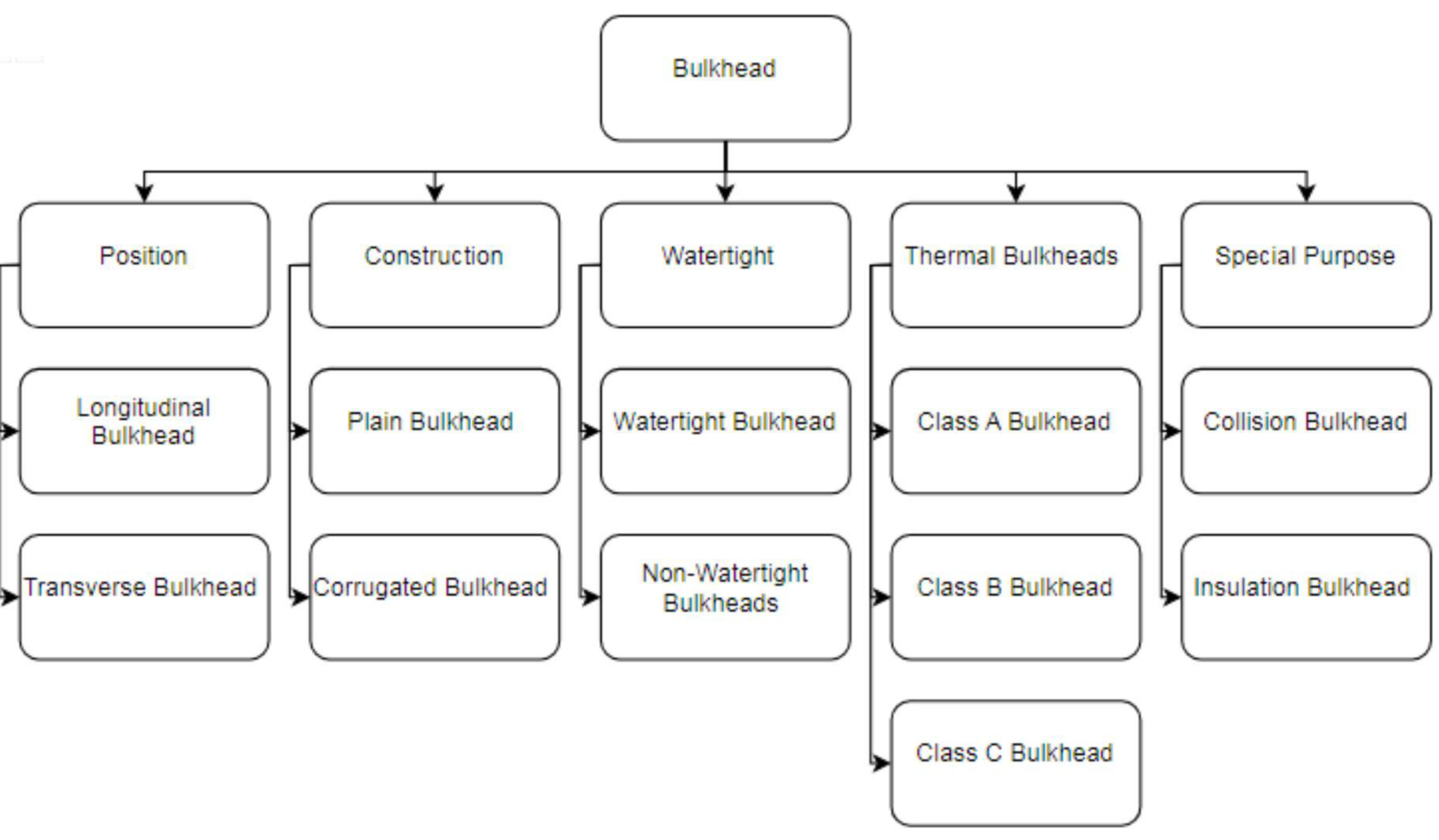
The important thing about the tree is that the four branches are independent. A given bulkhead has a position, a construction, a watertightness and possibly a special purpose, and all four apply at once. The collision bulkhead, for example, is transverse, plain, watertight and of special purpose — and answering with only one of those is answering a quarter of the question.
7.1.6 Transverse and longitudinal bulkheads
Though most watertight bulkheads are transverse in orientation, some ships also have longitudinal watertight bulkheads within a compartment for longitudinal compartmentalisation within a compartment. Other than watertightness, the transverse bulkheads also add to the transverse strength of the ship.
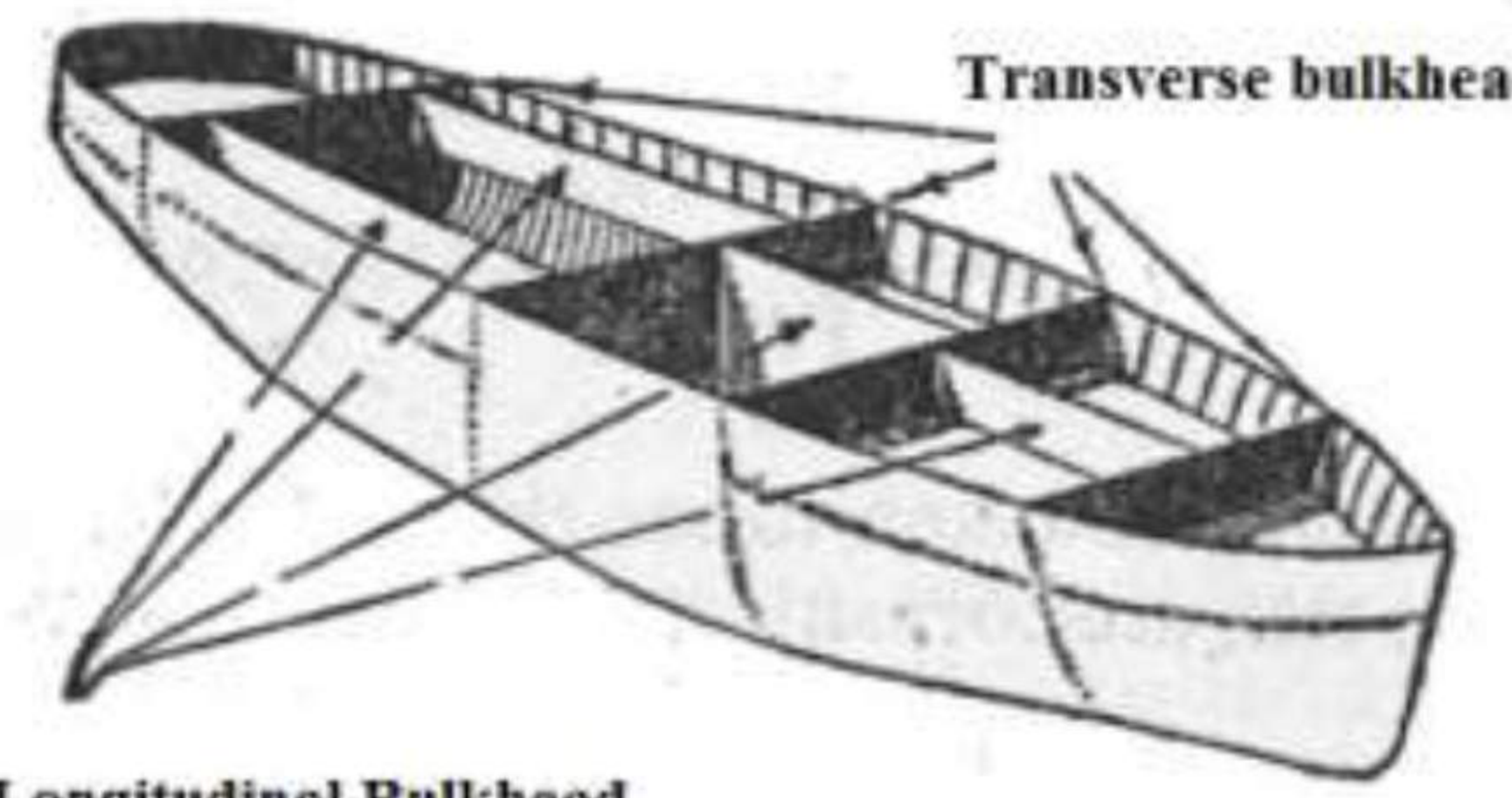
The two orientations are doing different jobs, and this is the comparison worth making:
| Transverse bulkhead | Longitudinal bulkhead | |
|---|---|---|
| Direction | Across the ship | Along the ship |
| Divides the ship | Into fore-and-aft compartments | Into port and starboard compartments |
| Structural contribution | Transverse strength — against racking | Longitudinal strength — where continuous, it adds to the hull girder |
| Racking resistance | The primary member | Contributes, but is the more common cause of the problem when discontinuous |
Where a longitudinal bulkhead is fitted, it is also a load the ship must be designed around: an off-centre longitudinal division, when one side is flooded, produces a heeling moment, which is why the longitudinal bulkheads in a tanker are paired symmetrically about the centreline. The tanker's centreline and wing bulkheads of Part 1 §1.1.2 are the familiar example.
7.1.7 Non-watertight bulkheads
Any bulkhead which does not form part of a tank or part of the watertight subdivision of the ship may be non-watertight.
Where they are fitted:
- Many are fitted in a ship, forming engine casings and partitions in accommodation.
- 'Tween deck bulkheads fitted above the freeboard deck may be of non-watertight construction, while many ships are fitted with partial centreline bulkheads if grain is to be carried.
- Centreline bulkheads and many deck-house bulkheads act as pillars supporting beams and deck girders, in which case the stiffeners are designed to carry the load.
- The remaining bulkheads are lightly stiffened by angle bars or welded flats.
The grain-feeder bulkhead is one of the more interesting rules and it is a reminder that the trigger for bulkheading is not always water. Grain is a dense free-flowing cargo that can shift bodily when the ship rolls, so a partial centreline bulkhead at the top of the hold reduces the free surface of the cargo in the same way that a wash plate reduces the free surface of a liquid.
There is one design idea running through that list and it is the reason the stiffener sizes vary so much between non-watertight bulkheads: a non-watertight bulkhead is not designed against a pressure at all, it is designed against the loads that come into it. Where it carries a deck girder it acts as a pillar and the stiffeners are sized for that compression; where it is only a partition the stiffeners are angle bars or welded flats installed to keep the panel flat and nothing more.
7.1.8 Watertight bulkhead in detail — the requirements
The full set, in the form the oral wants it:
| Item | Requirement |
|---|---|
| Number | Depends upon the length of the ship and the position of the machinery space. In ships more than 90 m in length, additional bulkheads are required, the number depending on the length |
| Whether the structure is kept watertight | It is essential. If it is found necessary to penetrate the bulkhead, precautions must be taken to ensure that the bulkhead remains watertight |
| The after engine room bulkhead | Penetrated by the main shaft, which passes through a watertight gland, and by an opening leading to the shaft tunnel. That opening must be fitted with a sliding watertight door |
| Pipes and cables | When pipes or electric cables pass through a bulkhead, the integrity of the bulkhead must be maintained |
The worked numbers for the number of bulkheads:
Thus a ship 140 m long will require a total of 7 bulkheads if the machinery is amidships, or 6 if the machinery is aft, while a ship 180 m in length will require 9 or 8 bulkheads respectively.
Read as a table against the SOLAS minimum in §7.4.4, that gives the shape of the rule: an additional bulkhead roughly every 20 m of length above 90 m, and the machinery case costs one more than the machinery-aft case because the machinery space has a bulkhead at each of its ends.
The specific bulkheads that must exist:
- A collision bulkhead, at least one twentieth of the ship's length from the forward perpendicular, and continuous up to the uppermost continuous deck.
- The stern tube must be enclosed in a watertight compartment formed by the stern frame and the after peak bulkhead, which may terminate at the first watertight deck above the waterline.
- A bulkhead must be fitted at each end of the machinery space, although if the engines are aft the after peak forms the after boundary of the space — in certain ships this results in the saving of one bulkhead.
- The list in MOT's own terms: collision bulkhead or fore peak bulkhead, after peak bulkhead, and one bulkhead at each end of the machinery space.
How they are built:
- These bulkheads must extend to the freeboard deck, and should preferably be equally spaced in the ship.
- The bulkheads are fitted in separate sections between the tank top and the lowest deck, and in the 'tween decks.
- Watertight bulkheads are formed by plates which are attached to the shell, deck and tank top by welding.
- Since water pressure increases with the head, and the bulkhead is to be designed to withstand such a force, the plating on the lower part of the bulkhead is thicker than that at the top.
- The bulkheads are supported by vertical stiffeners spaced 760 mm apart. Any variation in this spacing results in variations in the size of the stiffeners and the thickness of the plating.
- The ends of the stiffeners are usually bracketed to the tank top and deck, although in some cases the brackets are omitted, resulting in heavier stiffeners.
The 760 mm spacing and the bracket-or-no-bracket choice are the same trade stated twice: the stiffener is a beam, and its scantling depends on its span and on how its ends are fixed. A bracketed end is close to a fixed end and reduces the bending moment; omit the bracket and the stiffener must be heavier to carry the same load. The two statements are describing one design decision.
Testing watertight bulkheads — the subject of §7.6.
7.1.9 Testing the bulkheads: hose test, water head, and the alternatives
The hose test. Bulkheads are tested for watertightness by hosing them, using a pressure of 200 kN/m². If the hose test is not practicable — because of possible damage to machinery or electrical equipment insulation — it may be replaced by careful visual examination of the welded connection.
The water head test. Tanks intended to hold liquids, and which form part of the watertight subdivision of the ship, shall be tested for tightness and structural strength with a water head. The water head is in no case less than the top of the air pipes, or a level of 2.4 m above the top of the tank, whichever is greater.
The alternatives. Where a hose test is not used, the test can be done by dye penetrant test or an ultrasonic test, and the test is carried out from the side on which the stiffeners are attached.
The pressure test as the oral describes it:
After installation of the bulkheads, they are to be tested for their integrity and watertightness. Since it is not feasible to fill all the cargo holds or compartments with water for this purpose, the test is done by a pressure hose. In this process, the bulkhead is subjected to a prerequisite water pressure from a hose for a fixed period of time, after which the structural integrity of the bulkhead is inspected — checks are done for buckling and other deformations. Leak tests can also be done by pressurising the air in a compartment and checking for leakage of air to the other compartment.
The reason a hose is used instead of filling the compartment is the one that governs every test in this part: filling a cargo hold with water to prove the bulkhead is a static load the structure was never designed for, and would itself damage the ship. The hose applies the local pressure that the weld will actually see, and the surveyor inspects for what the test is really for — not only leaks, but buckling and deformation.
The instruction to test from the stiffener side is the detail that shows the test is understood: the stiffeners tell the surveyor which side of the plate the seams were run from, so he is standing where a defect in the weld would open towards him rather than being masked by the stiffener behind the plate.
7.2 Plain bulkheads
7.2.1 How a plain bulkhead is built
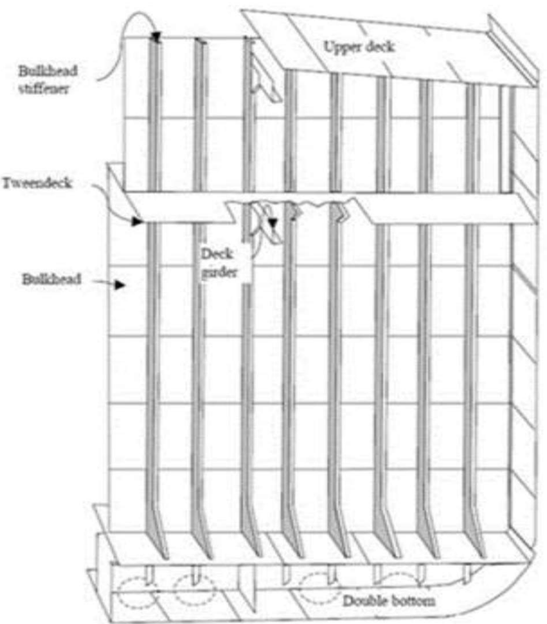
In small ships, a transverse bulkhead may be constructed from a single plate. For larger ships, the plating of a transverse bulkhead usually consists of a series of horizontal strakes, welded together.
The thickness of these strakes increases with depth, in order to strengthen the bulkhead against the maximum hydrostatic pressure in case the compartment is fully flooded. So prior to erection, two-dimensional strakes are first cut out from plates of different thicknesses.
The word hydrostatic in the phrase "maximum hydrostatic pressure" is the key to the direction of the increase: water pressure rises with head, that is with depth below the waterline, so the plate is thickest at the bottom where the head is greatest, and thinnest at the top where it is least. The strakes are cut before erection because the bulkhead is assembled from plates of different thickness and the sequence has to be known at the cutting stage.
In practice plate thickness could range from 7 mm at the top to 12 mm at the bottom.
7.2.2 Why plate thickness and stiffener size are linked
Also from the same account:
- Bulkheads are constructed of plates joined together and stiffened by vertical and horizontal stiffeners.
- As the water pressure increases with depth, the thickness of the plating in the lower part needs to be increased accordingly.
- The thickness of the plates used in the construction will also depend on the size of the stiffeners used to stiffen the bulkhead plating.
The third line is the one to be careful with, because it is the reverse of the intuitive direction. The plate and the stiffener are not independent: a bigger, stiffer stiffener supports a wider strip of plate between stiffeners, and a wider strip carries a greater total load, so the plate has to be thicker to span between the stiffeners. Increase the stiffener and the plate must follow; reduce it and it may be reduced. Designing one therefore settles the other.
7.2.3 Stiffening a plain bulkhead
The bulkhead plate itself is not resistant enough against large-scale transverse forces like shear forces. So they are stiffened, either vertically or horizontally. But we usually go for vertical stiffening instead of horizontal.
Why vertical rather than horizontal:
Because horizontal stiffening in ships with high beam would require stiffeners of long span, which would also increase the scantling and weight of the stiffener, affecting usable cargo volume. However, with vertical stiffening, the span — and hence the scantling — of the stiffener can be kept low by introducing a stringer at mid-depth (a stringer acts as a fixed end, therefore reducing the span).
The argument is the same span argument as Part 6 §6.2.1, applied to the other direction, and it is worth seeing it as one principle rather than two rules:
| Horizontal stiffener | Vertical stiffener | |
|---|---|---|
| Span | The breadth of the ship — long, and growing with beam | The height of the bulkhead — short |
| Consequence | Bigger scantling, more weight, less cargo volume | Smaller scantling |
| How to control it further | — | A stringer at mid-depth acts as a fixed end and halves the span |
The stiffener runs the short way, and the stringer is the device that makes the short way even shorter. A bulkhead spanning 12 m athwartships with no intermediate support needs a very heavy stiffener; the same bulkhead with vertical stiffeners spanning 4 m in height, halved again by a stringer at mid-depth, needs two much smaller ones.
Which sections are used. The sections used for stiffening bulkheads are usually flat bars, angles or bulb bars, depending upon the required section modulus — the same set as Part 5 §5.2.1, chosen by the same criterion.
7.2.4 The end conditions of bulkhead stiffeners
An important aspect of the design of bulkhead stiffeners is meeting the end conditions. In order to meet the boundary conditions so that the stiffeners respond as per the theoretical calculations, their end supports must be designed accordingly:
| Desired condition | How the support is made |
|---|---|
| Hinged end | The stiffener is attached to the underside of the deck plating with brackets |
| Fixed end | The stiffener is welded directly to the deck plate and the stringer |
This is the detail that turns the stiffness calculation from arithmetic into design. A stiffener's bending moment under the same load differs by a factor of two between a simply-supported end and a fixed end, so the analysis is only valid if the detail at the end actually delivers the condition assumed. A bracket gives rotation but not moment — hinged; a direct weld gives both — fixed. Which one is used is decided by the scantling calculation, and this is one of the very few places where the connection detail of a member is stated as a design input rather than a consequence.
7.3 Corrugated bulkheads
7.3.1 How a corrugated bulkhead is formed
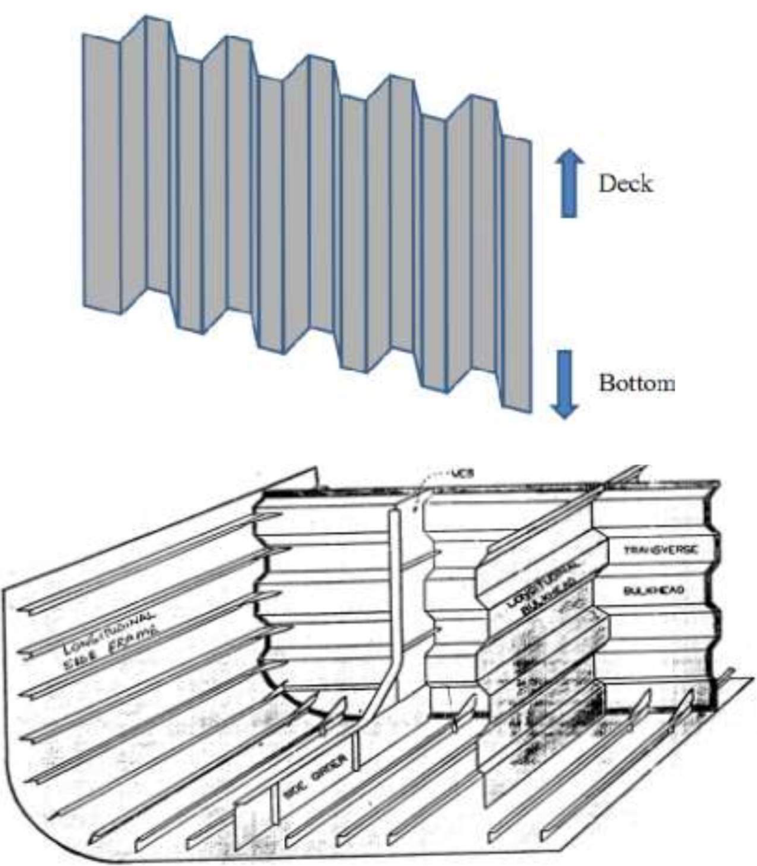
Most modern-day ships use an advanced technology to achieve the required strength of bulkhead plates. They use corrugated bulkheads instead of stiffened ones. The corrugations are in the vertical direction, except when the breadth of the bulkhead is significantly low.
The trade-off:
Since the corrugations are provided on the bulkhead plate right in the early fabrication stage, corrugated bulkheads are made of plates having uniform thickness — that is, the thickness equal to the lowermost strake in the case of a conventional bulkhead. This increases the weight of the bulkhead when compared to a conventionally stiffened bulkhead. In spite of this, the usage of corrugated bulkheads comes in handy due to ease in fabrication and reduction of welded joints on the bulkhead.
That trade-off is the answer to "why corrugate", and it is a straight comparison of two costs:
| Plain stiffened bulkhead | Corrugated bulkhead | |
|---|---|---|
| Material | Strakes of increasing thickness with depth; separate stiffeners | One uniform plate thickness, equal to the deepest strake of the plain bulkhead |
| Weight | Lighter | Heavier — the upper part has more material than it needs |
| Fabrication | Plates plus a large number of stiffeners to line up and weld on | Corrugations formed in the plate itself; fewer welded joints |
| Result | Minimum weight, more work | More weight, less work |
7.3.2 Corrugated bulkhead in detail
The purpose of the corrugation:
- Corrugations (or swedges) are formed on a corrugated bulkhead to eliminate the need to fit the vertical stiffeners, as in those of the plain bulkhead.
- The elimination of vertical stiffeners also results in saving in steel weight and cost of stiffeners.
- The angle of corrugation is normally about 45 degrees.
- The troughs are vertical on transverse bulkheads, but must be horizontal on continuous longitudinal bulkheads, which form part of the longitudinal strength of the ship.
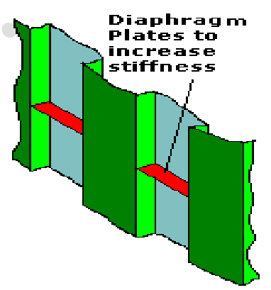
- Diaphragm plates or horizontal stringers are fitted on the bulkhead to keep the corrugation in place.
- This bulkhead forms a very smooth surface in oil tanks, allowing improved drainage and ease of cleaning.
Why the corrugation works: a corrugated plate is stronger than a flat plate if subjected to a bending moment or pillar load along the corrugations.
That is the whole structural principle in one line. A flat plate under pressure bends across its thickness, and its resistance is only its own section modulus. Corrugate it and the plate's material is now arranged out of the plane of the wall — the folds give it depth in the direction of the load, exactly as a rolled section gives a stiffener its depth. The corrugation is the stiffener, formed out of the plate itself.
The orientation rule follows directly from the same principle and is the detail most often got wrong:
| Bulkhead | Trough direction | Why |
|---|---|---|
| Transverse bulkhead | Vertical | The load is water pressure from one side; vertical troughs give depth against that pressure and let the corrugations stand on the tank top |
| Continuous longitudinal bulkhead | Horizontal | The bulkhead is part of the longitudinal strength of the ship, so the corrugations must run across the ship's bending direction to add to the hull girder |
A longitudinal bulkhead corrugated the other way would be a series of vertical folds in a fore-and-aft wall — strong against water pressure across the ship, but contributing nothing to the lengthwise bending it is there to share.
Where they are fitted:
Corrugated bulkheads are used as the bulkhead of the cargo hold compartment of some kinds of vessels, for:
- easier maintenance,
- easier loading and unloading,
- more flexible shape in shrinkage and expansion by thermal load compared to the flat stiffened bulkhead.
They can be commonly seen in bulk carriers, product oil carriers and chemical tankers. Instead of stiffeners the bulkhead may be corrugated or swedged. Corrugations are centred over the DB girders and placed over a watertight DB tank floor. A horizontal diaphragm plate is used in the trough to strengthen the bulkhead.
And their benefit in the terms of the loading trade: reduced weight, smooth surface helps in cleaning cargo residues from bulkheads. Can withstand bending moments and pillar loads. In the case of corrugated bulkheads, the stiffening of the flange is made by the corrugation web.
Note the two reasons that are both worth carrying: the thermal load — the corrugation tolerates the shrinkage and expansion of a cargo that is loaded hot, which a flat stiffened bulkhead does not — and the smooth surface, of which the oil-tanker drainage benefit and the cargo residue cleaning benefit are the same property used in two trades.
7.3.3 Corrugated against flat, and where each is used
Reading the two accounts together:
| Corrugated | Plain, stiffened | |
|---|---|---|
| Strength built in | Inherently formed in construction — the corrugation is the stiffener | Requires a lot of extra strengthening to be added to withstand hydrostatic pressure |
| Weight | Large reduction in weight from omitting stiffeners, but a uniform plate thickness slightly heavier than the straked plate | Strakes of varying thickness, optimised for head |
| Where used | Mostly dry cargo ships, often in oil tankers; common in bulk carriers, product oil carriers and chemical tankers | Where the weight saving matters most, and where simple fabrication is not decisive |
| Benefit in tanks | Very smooth surface — improved drainage, easier cleaning | Stiffeners trap residue |
The comparison to give is therefore not "corrugated is better" but which cost is being traded. A corrugated bulkhead buys fabrication simplicity, a smooth tank surface, few welded joints and thermal tolerance at the price of plate weight. It is bought where the cargo is dirty (oil, chemicals), where cleaning matters, or where the bulkhead has to put up with thermal cycling; it is not bought where minimum weight is the governing requirement.
7.3.4 The "T" deck and bulkhead intersections
Where a bulkhead meets a deck the two structures intersect, and the intersection has a name and a figure of its own: the T deck.
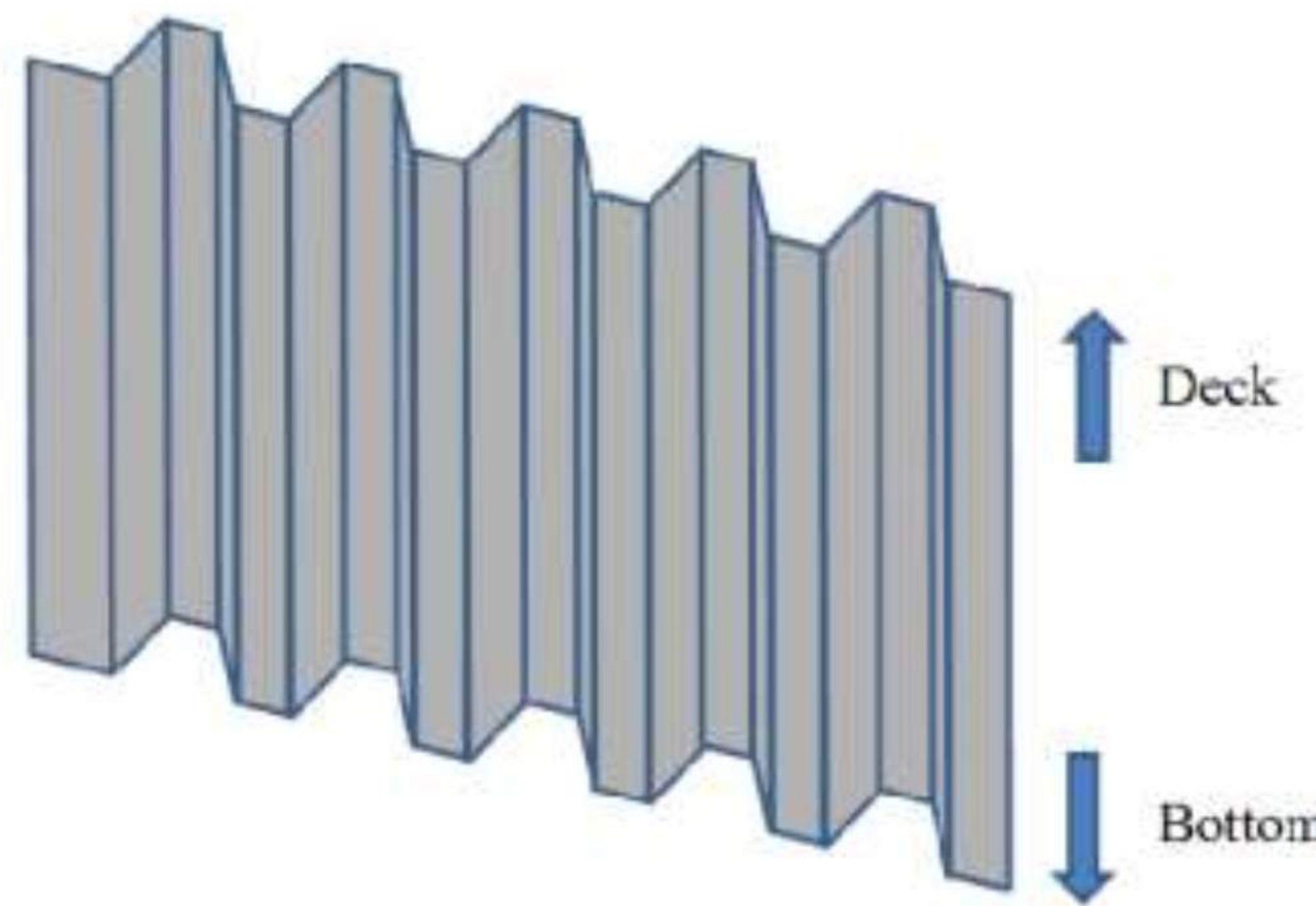
The geometry is what the name describes: the deck plate runs out horizontally on both sides of the bulkhead, and the bulkhead plate runs through it vertically, so the section at the intersection looks like a T with the bulkhead as the stem. Drawing it in section is the standard way to show that the two members are continuous through the intersection rather than one being interrupted by the other — the same point Part 6 §6.4.1 makes about the centre girder and the plate floors, where the plate floor is cut and welded either side of the girder rather than the other way round.
7.4 The two special bulkheads
7.4.1 Collision bulkhead — position and purpose
A collision bulkhead is the forward-most bulkhead in a ship. It is a heavy-duty bulkhead in the forepart of the vessel, to withstand damage after impact from a collision — a forepeak watertight bulkhead, its purpose to protect against foundering and against racking stress.
The purpose, stated fully:
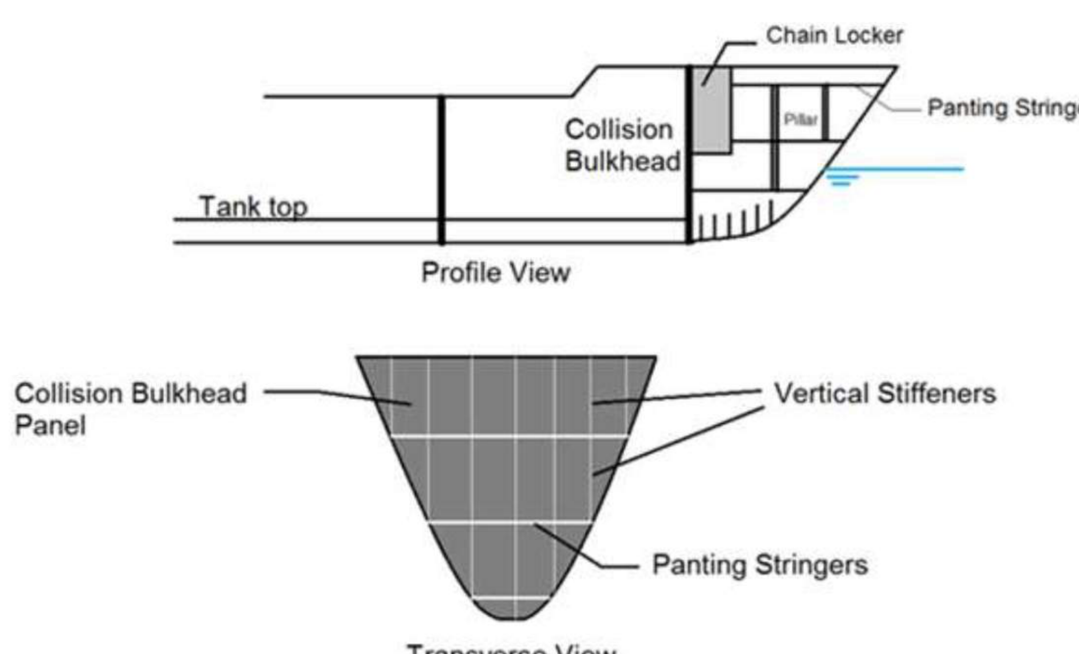
The collision bulkhead is a heavily strengthened structure, its main purpose being limiting the damage of a head-on collision to the part of the bow forward of it. To limit the damage to its forward region also means that the collision bulkhead is a watertight bulkhead. It is usually vertically stiffened with sections of scantlings higher than those on the surrounding structures. It is also stiffened by triangular stringers of higher scantling, called panting stringers. Panting stringers are usually provided at every 2 metres from the bottom, forward of the collision bulkhead.
Everything the bulkhead is doing follows from "forward of it". The bulkhead is the after boundary of the fore peak — the one compartment the ship is prepared to lose to a head-on impact — and the whole of the structure forward of it is arranged on the assumption that the plating there may be torn open. That is the reason it is the heaviest bulkhead on the ship, and the reason its stiffening is stated as being of higher scantling than the surrounding structures rather than by a dimension.
7.4.2 Collision bulkhead — the position rules
There are three factors that determine the position of the forward collision bulkhead, and the final position is decided so that it takes into consideration all of them:
| Factor | Basis |
|---|---|
| Factor 1 | Position based on floodable length calculations |
| Factor 2 | Position based on the classification society code books — most have an allowable range of distance from the forward-most point of the hull, usually a function of the length of the ship and the shape of its bow |
| Factor 3 | Position based on the SOLAS rule |
The SOLAS rule (Factor 3):
The collision bulkhead should be located aft of the forward perpendicular at a distance not less than 5 per cent of the ship's length, or 10 metres, whichever is less. The distance must also not exceed 8 per cent of the ship's length.
And the practical override, which is the fourth constraint in practice:
However, the position of the collision bulkhead should be such that maximum cargo storage volume is achieved.
The MOT version of the same rule:
It is fitted not less than 5 per cent or not more than 7 per cent of the ship's length aft of the stem at the load waterline. It must extend to the upper deck. Stiffeners may be spaced 600 mm apart.
The two accounts differ on the upper limit — 8 per cent against 7 per cent — and on the lower reference point, which is given as the forward perpendicular in one and the stem at the load waterline in the other. Both are quoted above. The lower bound is the same in all three.
The subdivision reason behind the position — this is the derivation the oral is usually after:
- In the event of collision and grounding, the standard of subdivision has to give a good chance that the ship remains afloat under such emergencies.
- Transverse bulkheads are reliable in this case, and the classification society requires a watertight collision bulkhead within a reasonable distance from forward.
- If the ship is supposed to have a wave trough amidships, there will be excess weight amidships and excess buoyancy at the ends, hence the ship will be sagging.
- If the ship is supposed to have a wave crest amidships, there will be excess weight at the ends and excess buoyancy amidships, hence the ship will be hogging.
- By "trochoidal theory", the wave height from trough to crest is 1/20 of the wavelength.
- Therefore maximum shearing force usually occurs at about L/20 of the ship from each end.
- For this reason the collision bulkhead is located L/20 of the ship length.
So L/20 is not a round number chosen for convenience. It is the point where the shear force in the hull girder peaks as a wave passes, and the bulkhead is placed there because that is where the structure is working hardest and needs the transverse stiffness most. Note that L/20 is 5 per cent — the same as the SOLAS lower bound — which is what makes the two rules agree.
7.4.3 Collision bulkhead — the openings rule
As per SOLAS rules:
- The collision bulkhead must be watertight up to the bulkhead deck. A bulkhead deck is the deck level up to which all the watertight bulkheads are extended.
- For access to the chain locker room and the forward part of the bulkhead, steps may be provided on the collision bulkhead. However this must not violate Factor 3 — that is, the steps must not push the bulkhead outside the 5–8 per cent band.
- There must be no doors, manholes, access hatches, ventilation ducts or any openings on the collision bulkhead below the bulkhead deck. However, the bulkhead can be allowed to have only one piercing below the bulkhead deck, for the passage of one pipe to cater to the fluid flow to the forepeak ballast tank. The passage of the pipe must be flanged and must be fitted with a screw-down valve which can be remotely operated from above the bulkhead deck. This valve is usually located forward of the collision bulkhead; however, the classification society certifying the ship may authorise a valve aft of the bulkhead, provided it is easily serviceable at any condition and is not located in the cargo area.
- In case of ships having superstructures at the forward region, the collision bulkhead is not terminated at the bulkhead deck. It must be extended to the deck level next to the weather deck. This ensures sufficient structural continuity and keeps the shear forces within safe limits.
- If the collision bulkhead is extended above the freeboard deck, the number of openings on the bulkhead should be restricted to a minimum, in order to ensure sufficient buckling strength. All the openings should be watertight.
The one-piercing rule is the clearest example in the whole part of how a bulkhead's watertightness is graded rather than absolute. The bulkhead is not required to be a perfect wall — it is required to be a wall with exactly one carefully specified hole in it, for a pipe that the forepeak ballast tank cannot do without, closed by a valve the officer can work from the deck above. Everything else — doors, manholes, hatches, ventilation ducts — is banned below the bulkhead deck, because each one is a potential path for water into the ship from the compartment the bulkhead exists to sacrifice.
7.4.4 The minimum number of bulkheads
As per Lloyd's Register:
| Length of ship (m) | Machinery amidships | Machinery aft |
|---|---|---|
| 90–105 | 5 | 5 |
| 105–115 | 6 | 5 |
| 115–125 | 7 | 6 |
| 125–145 | 8 | 6 |
| 145–165 | 9 | 7 |
| 165–190 | — | 8 |
The pattern in the table is the one §7.1.8 states in words: the count rises with length, and the machinery-aft arrangement needs one fewer bulkhead in the middle ranges because the after peak already serves as the after boundary of the machinery space. Note that the two columns converge at the shortest lengths — a 90–105 m ship needs 5 whether the machinery is amidships or aft.
7.4.5 After peak bulkhead
The after peak bulkhead encloses the stern tube in a watertight compartment.
Its extent:
This bulkhead need only extend to the first deck above the load waterline, if it forms a watertight flat.
That is the one place in this part where a watertight bulkhead is allowed to stop short. The rule is not an exception to the principle but an application of it: the bulkhead exists to keep water out of the after body if the stern is damaged, and once the deck above the waterline is itself watertight, carrying the bulkhead any higher buys nothing.
Its scantlings:
Plating in the after peak bulkhead must be doubled or thickened around the stern tube, to resist vibration.
The reason is the one established in Part 4 §4.5: this bulkhead is immediately forward of the propeller and the rudder, and it is penetrated by the shaft. The doubling is not for water pressure — it is for the vibrating load the propeller puts into the structure around the shaft, and for the stress concentration the penetration itself creates.
The connection to the rest of the after end: the stern tube must be enclosed in a watertight compartment formed by the stern frame and the after peak bulkhead, which as noted may terminate at the first watertight deck above the waterline.
7.5 Thermal and fire boundaries
7.5.1 Thermal class bulkhead
Thermal bulkheads are one of the classifications under special purpose in the bulkhead tree. The name describes the duty: a thermal bulkhead is a division whose classification is set by what it does to heat rather than to water, and it is therefore specified in terms of temperature rise on the far side and time rather than in terms of heads of liquid.
That is the difference between the two ways of specifying a bulkhead, and it is worth stating plainly because the two systems share the same letters:
| Watertight bulkhead | Thermal / fire class bulkhead | |
|---|---|---|
| Designed against | A head of water | A fire, for a stated time |
| Specified by | Plate thickness against depth, stiffener spacing, water test | Insulation and temperature rise limits over a stated time |
| Classification | Watertight or non-watertight | A-60, A-30, A-15, A-0; B-15, B-0; C |
7.5.2 Fire class of bulkheads — A, B and C
In order to prevent the propagation of fire from one compartment to another, all watertight bulkheads are also provided with fire-resistant panelling. However, depending on the extent to which bulkheads can retain the fire and smoke to the affected side, they are classified into three categories.
Class A panel
- All watertight bulkheads are Class A type.
- Bulkheads of Class A must be constructed of steel or equivalent material, and should pass the standard fire test, preventing the passage of fire or smoke to the unaffected side for at least one hour.
- With Class A bulkheads in use, the average temperature on the unaffected side must not exceed 120°C.
- Added to that, there are three categories of Class A panels depending on the time up to which the temperature at any point on the bulkhead must not rise above 160°C:
| Panel | Time |
|---|---|
| A-60 | 60 minutes |
| A-30 | 30 minutes |
| A-15 | 15 minutes |
| A-0 | 0 minutes |
Class B panel
- Bulkheads of Class B are constructed of materials approved by SOLAS and classification societies as incombustible materials, and should pass the standard fire test, preventing the passage of fire or smoke to the unaffected side for at least thirty minutes.
- With Class B bulkheads in use, the average temperature on the unaffected side must not exceed 120°C.
- There are two types of Class B panels, depending on the time up to which the temperature at any point on the bulkhead must not rise above 206°C:
| Panel | Time |
|---|---|
| B-15 | 15 minutes |
| B-0 | 0 minutes |
Class C panel
Class C bulkheads and decks are constructed of materials approved by SOLAS and classification societies as incombustible, but they are not required to meet any requirements related to rise in temperature or passage of smoke and flame to the unaffected side.
Where each panel class is used
Class A and B panels are used adjacent to most of the enclosed spaces within the ship — for example cargo holds, control stations, stairways, lifeboat embarkation stations, galleys, machinery spaces, tanks, public spaces and accommodation areas. Class C panels are mostly used in open decks and promenades, where the requirement of fire safety is minimum. They can also be used between two similar spaces if they are not separated by a watertight bulkhead, in which case a Class A panel is mandatory.
That last clause is the one worth holding: the watertight bulkhead governs the fire class, not the other way round. Where a division is watertight it must be Class A, whatever the two spaces either side of it are, because the watertight bulkhead runs the full depth of the ship and a fire in one compartment would otherwise have a path past the deck.
The two temperature criteria
Every class above is specified by the same pair of numbers, and the pair is the point:
| Average rise on the unexposed side | Maximum rise at any one point | |
|---|---|---|
| Class A | 120°C | 160°C |
| Class B | 120°C | 206°C |
Note the asymmetry, which mirrors the same asymmetry in the KS3 account of the same classes: the average limit is the same for both classes, while the point limit is much more generous for Class B. The average is what governs the survivability of the space behind; the point limit is what governs whether the division holds locally, at a joint or a penetration.
7.5.3 The same classes in the SOLAS form
The same three classes are also set out in the SOLAS form, and the numbers differ. Both sets are given here, because the question may be put either way:
| Class A | Class B | |
|---|---|---|
| Construction | Steel or other equivalent material, suitably stiffened | Approved non-combustible materials throughout |
| Average temperature of the unexposed side | Not more than 140°C above the original temperature | Not more than 140°C above the original temperature |
| Maximum at any one point, including any joint | Not more than 180°C above the original temperature | Not more than 225°C above the original temperature |
| Smoke and flame | To the end of the one-hour standard fire test | To the end of the first half-hour standard fire test |
| Grades | A-60, A-30, A-15, A-0 | B-15, B-0 |
And Class C: divisions constructed of approved non-combustible materials, which need meet neither requirements relative to the passage of smoke and flame nor limitations relative to the temperature rise.
The conflict, stated plainly. The two sets give different figures for the same statutory classes, and the difference is not trivial:
| One set of figures | The SOLAS figures | |
|---|---|---|
| Class A average rise | 120°C | 140°C |
| Class A point rise | 160°C | 180°C |
| Class B average rise | 120°C | 140°C |
| Class B point rise | 206°C | 225°C |
The SOLAS figures are the ones to quote for a statutory question. The other set appears to be a paraphrase, and its 120°C/160°C/206°C set should not be used for a class question without checking against the convention. The structural content of both accounts agrees completely — the same A-60/30/15/0 and B-15/0 grades, the same construction requirements, the same one-hour and half-hour smoke and flame periods.
7.5.4 The standard fire test as the basis of the classification
Every one of the classes above is defined by reference to one test, and the test has its own definition:
A standard fire test is a test in which specimens of the relevant bulkheads or decks are exposed in a test furnace to temperatures corresponding approximately to the standard time-temperature curve, in accordance with the test method specified in the Fire Test Procedures. The specimen shall have an exposed surface not less than 4.65 m² and height 2.44 m, including at least one joint.
The shorter form: the exposure of a material, or of a specimen, in a test furnace to a particular temperature for a certain period of time.
The classification is therefore empirical throughout. "A-60" is not a description of how a bulkhead is built — it is the result of an actual test: this specimen, in this furnace, on this time-temperature curve, held for sixty minutes, with the temperature rise on the far side measured and compared against the limits. The two numbers in §7.5.2 are the measure, the grade is the outcome, and the one joint required in the specimen is there because the joint is where a fire gets through.
7.5.5 The FTP Code and its significance
FTP Code (International Fire Test Procedure Code):
- It contains fire test procedures for fire-safe constructions and materials used on board ships.
- It uses a fire test which covers non-combustibility, fire resistance, flammability, spread of flame, smoke and toxicity of constructions and material.
- The significance of the FTP Code is that it will set higher fire safety requirements and thereby improve the protection of ships against catastrophic fires.
The Code is what makes the phrase "in accordance with the Fire Test Procedures" in §7.5.4 a defined term rather than a general reference. Without it, each administration would test its own way and an "A-60" bulkhead would mean one thing in one yard and something else in another; with it, the furnace, the time-temperature curve and the six properties listed above are the same on every approving authority, which is why a class certificate travels with the material.
7.6 Void spaces
7.6.1 Cofferdam
A cofferdam is a narrow void space between two bulkheads or floors that prevents leakage between the adjoining compartments.
The definition is short but it fixes all three of the things that matter:
| Element | Why |
|---|---|
| Narrow | It is a gap, not a compartment — it is there to be empty |
| Void | Nothing is carried in it, and nothing is stored in it |
| Between two bulkheads or floors | It is bounded by the two divisions whose contents must not meet |
It appears in the same role each time: in motor ships, where a drain tank is required under the machinery, a cofferdam is fitted, giving access to the holding-down bolts and isolating the drain tank from the remainder of the double bottom tanks.
That example shows both functions at once, and it is the way to answer the question:
- Isolation. The drain tank holds oily water from the machinery space; the double bottom tanks around it hold fuel or ballast. Without a void between them, a leak in either boundary puts oil into the ballast or water into the fuel.
- Access. The holding-down bolts of the machinery are inside the cofferdam, so the space that isolates the two liquids is also the space a person can enter to work on the engine seatings.
The general principle is that a cofferdam is provided wherever two spaces hold substances that must not mix — which in practice means oil on one side of it and anything else on the other, whether that is a cargo tank, a fresh water tank or a machinery space. A cofferdam is also a common place for the sounding pipes and the bilge arrangements of the spaces around it, for the same reason: the one space that is meant to be empty is the one where a leak shows up first.
7.6.2 Cofferdam vent
All tank vessels, the construction or conversion of which was started on or after 10 November 1936, cofferdams and void spaces shall be provided with gooseneck vents fitted with a flame screen, or pressure-vacuum relief valves. The diameter of a vent shall be not less than 2½ inches.
The requirement follows from §7.6.1 and is the thing that stops a cofferdam from becoming a hazard in its own right. A void space that can be entered, that is bounded by oil tanks, and that may accumulate hydrocarbon vapour, is an enclosed space; the vent ensures that the pressure inside it stays atmospheric as the surrounding tanks breathe and as the structure heats and cools. The flame screen or pressure-vacuum relief valve is what makes the vent safe to have: the cofferdam has to be able to breathe out when its neighbours are being loaded, and must not be able to pass a flame back into a space which may hold vapour.
7.7 Summary — the bulkhead picture
| Bulkhead | Position | Duty | Specified by |
|---|---|---|---|
| Collision | 5–8% of L abaft the forward perpendicular (L/20 for shear) | Limit head-on collision damage to the fore peak | Heavy scantlings, vertical stiffeners, panting stringers at 2 m, one flanged piercing with a screw-down valve |
| After peak | At the stern frame, enclosing the stern tube | Keep the after body watertight | Need extend only to the first deck above the waterline if that deck is a watertight flat; plating doubled around the stern tube against vibration |
| Machinery space | One at each end | Boundary of the machinery space | Extend to the freeboard deck; shaft gland and sliding watertight door in the after boundary |
| Transverse watertight | Subdivision, preferably equally spaced | Flooding, transverse strength, fire, cargo separation | Plate 7 mm top to 12 mm bottom, stiffeners at 760 mm, hose test at 200 kN/m² or water head to 2.4 m above the tank |
| Longitudinal watertight | Within a compartment | Longitudinal compartmentalisation; longitudinal strength when continuous | Corrugations horizontal |
| Corrugated | In place of a stiffened bulkhead | Same duties, with fewer welded joints and a smooth tank surface | Corrugation at about 45°, diaphragm plates, uniform plate thickness |
| Non-watertight | Casings, accommodation, tweendecks, centreline | Partition, pillar, grain subdivision | Light angle bars or welded flats; stiffeners sized for the load they carry |
| Fire class A | Watertight bulkheads and most enclosed spaces | One hour of smoke and flame containment | Steel, stiffened, insulated; A-60/30/15/0 |
| Fire class B | Accommodation divisions | Half an hour of smoke and flame containment | Approved non-combustible throughout; B-15/0 |
| Fire class C | Open decks, promenades | Non-combustible only | No temperature or smoke requirement |