
Ship Stresses and Longitudinal Hull Strength
What the sea does to the structure: shear and bending moment, hogging and sagging, racking and torsion, and the section modulus of the midship section that answers them.
Key Principles at a Glance 8 points
- Weight and buoyancy balance in total but not section by section; the excess of one over the other at each section is the load, and that imbalance is the only thing that bends a hull girder.
- Sagging is the hull bending concave upwards with the crest of a wave amidships; hogging is the reverse, with the trough amidships. Both are answered by the same longitudinal material.
- Shear force and bending moment are zero at the ends and greatest near midships, which is why the midship region carries the heaviest scantlings.
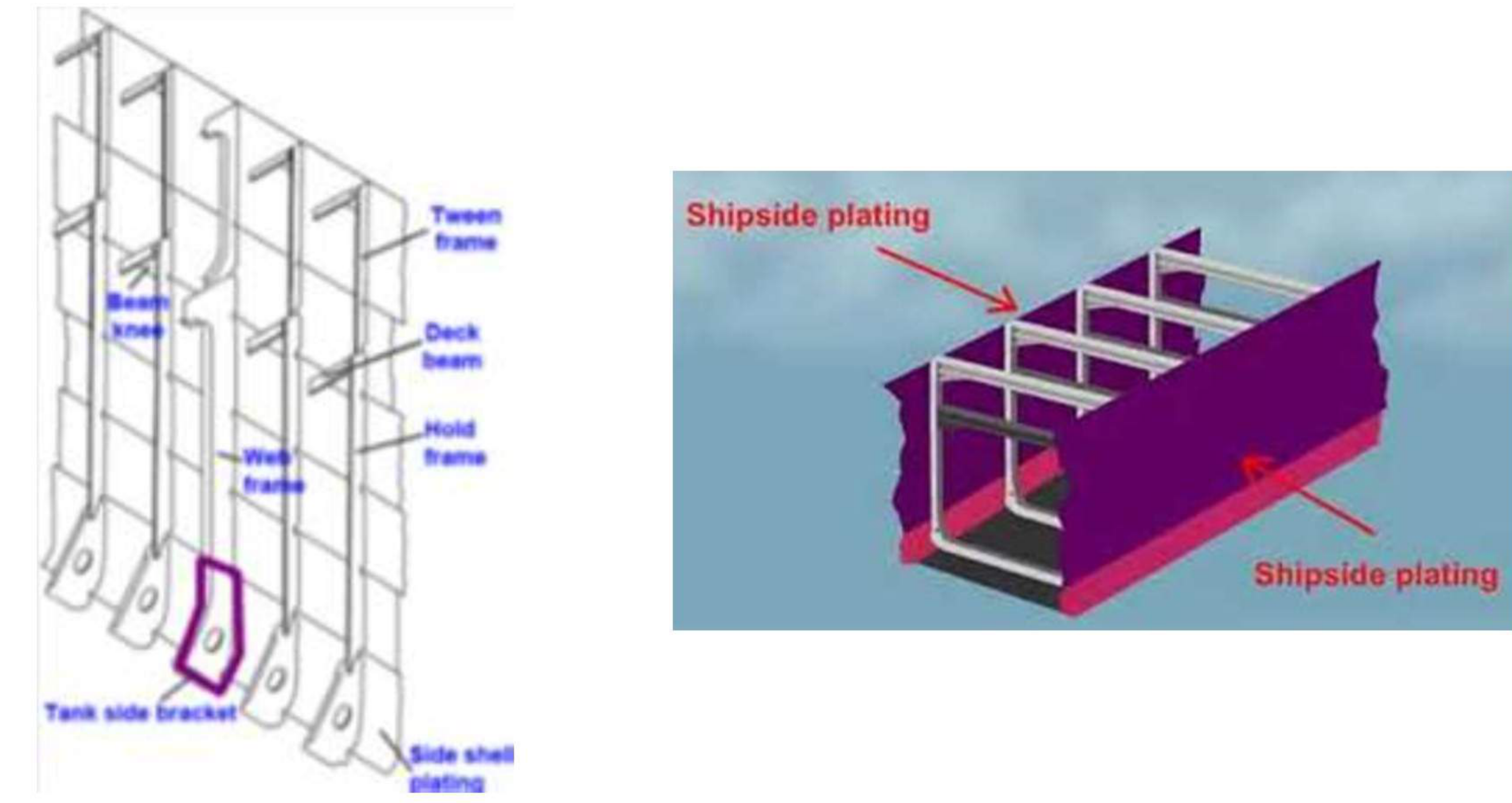
- Racking is the tendency of a transverse section to fold sideways when the ship rolls, and the beam knee and deck beam brackets are the members that hold the corner square.
- Torsion is worst when the ship meets a wave obliquely, with the bow and stern in opposite wave systems; a closed torsion box under the deck is what resists it.
- Panting is the in-and-out bellowing of shell plating forward under varying water pressure and it fails by fatigue; pounding is slamming of the forefoot and it fails by buckling.
- Longitudinal bending is resisted by the section modulus of the midship section, so material placed far from the neutral axis — deck and bottom — does the most work for its weight.
- Hull vibration is classified by its source: main machinery, the propeller, and the sea. Synchronous vibration is the dangerous case, because the hull is being driven at a natural frequency.
4.1 The fundamental loads
What the sea does to the structure. Every stiffening arrangement in the parts that follow is an answer to one of these loads.
4.1.1 Load
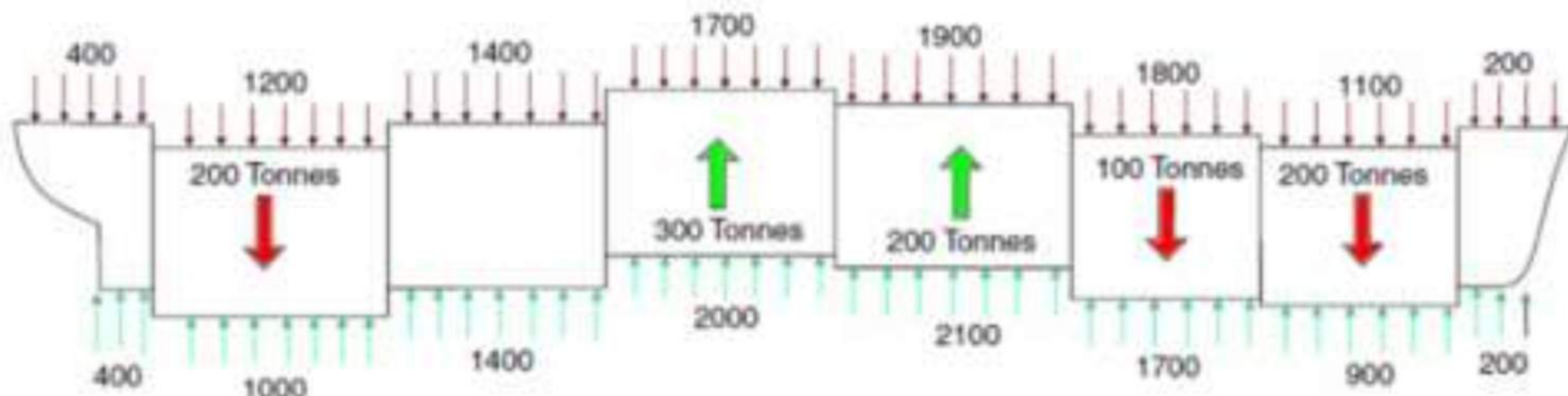
A ship floating in still water carries an unevenly distributed weight, owing to both the cargo distribution and the structural distribution herself. The buoyancy distribution is also non-uniform, because the underwater sectional area is not constant along the length, and because the vessel may be trimmed.
Total weight and total buoyancy are balanced. At each section, however, there will be a resultant force — a load — which is either an excess of buoyancy or an excess of weight. That section-by-section imbalance, and nothing else, is what bends the hull girder.
4.1.2 Shearing force
Shearing force is that type of force which causes, or tends to cause, two adjacent parts of the same body to slide relative to each other in a direction parallel to their plane of contact.
Both shear and bending moment are given a sign, and the convention is the one to draw:
| Positive | Negative | |
|---|---|---|
| Shear | The left-hand part tends to move up relative to the right | The left-hand part tends to move down relative to the right |
| Bending | The element bends concave upwards — the classic sagging sense | The element bends concave downwards — the hogging sense |
4.1.3 Bending moment
A bending moment exists in a structural element when a moment is applied to the element so that the element bends. Moments and torques are measured as a force multiplied by a distance, so the unit is the newton-metre.
The formal definition, which is the one to quote:
The bending moment at a section through a structural element may be defined as the sum of the moments about that section of all external forces acting to one side of that section.
When a bending moment exists in a structural element it induces tensile stresses and compressive stresses in that element. Both at once, on opposite faces: that is the whole mechanism by which a bending moment becomes damage.
Unit = newton-metre (force × distance)
4.1.4 The types of stress on a ship
Every stress a ship's structure is designed against falls into one of the following groups:
- Longitudinal stresses — hogging and sagging.
- Transverse stresses — racking, and the effects of water pressure.
- Local dynamic stresses — panting and pounding.
- Other stresses — those caused by drydocking, local weights, and vibration.
The single most important statement in this part: the greatest stresses set in the ship as a whole arise from the distribution of load along the ship, causing longitudinal bending. Racking, panting and pounding do real damage, but they are local and they are secondary to the bending of the hull girder.
The forces acting on a ship may be static or dynamic:
- The static forces are due to the difference in weight and buoyancy, which occurs throughout the ship.
- The dynamic forces are caused by the motion of the ship at sea, the action of the wind, and the action of the wave.
4.1.5 Shear force and bending moment curves
The shear force and bending moment vary continuously along the length, and their distribution is plotted as curves. The load curve, the shear curve and the bending moment curve are related in sequence:
- The load diagram
q(x)gives the section imbalance. - Its integral is the shear force diagram
F(x). - The integral of the shear force diagram is the bending moment diagram
M(x).
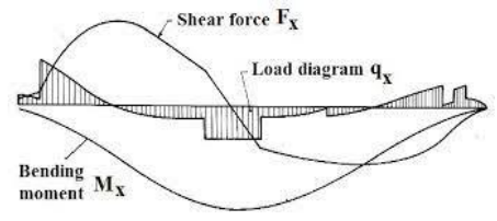
The loading instrument on board reproduces exactly these curves for the ship's actual condition, and it is what the ship's officer reads to know whether the voyage is acceptable. Its output is discussed in §4.3.2.
4.2 Hogging and sagging
4.2.1 Sagging
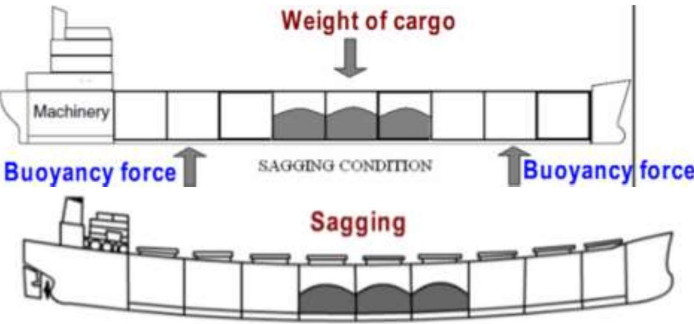
When a vessel bends with excess weight at the amidships, she is said to be sagging. When sagging, the deck is in compression and the bottom shell is in tension.
Stated as the distribution of weight and buoyancy along the length:
Sagging is the condition of a floating ship when the distribution of weight and buoyancy along her length is such that the weight amidships exceeds the buoyancy.
4.2.2 Hogging
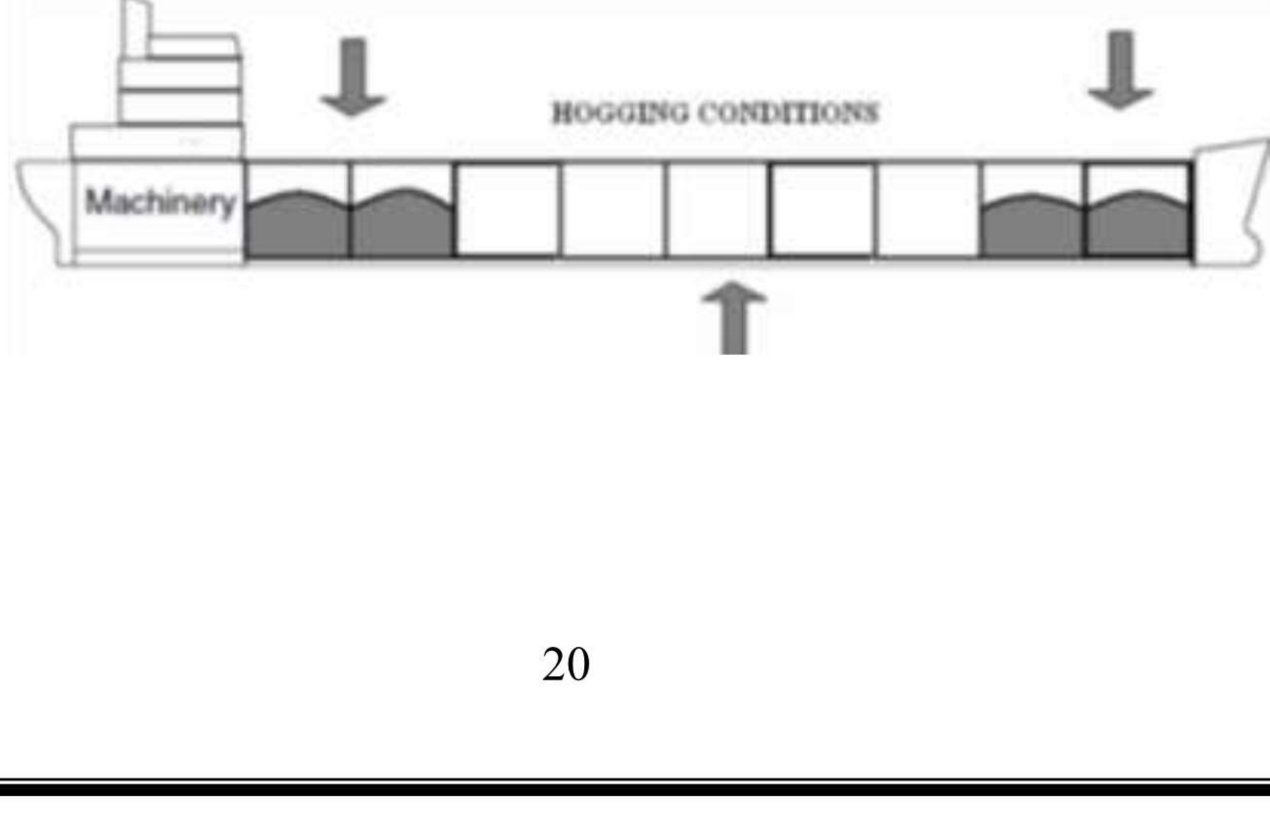
When a vessel bends with excess weight at the ends, she is said to be hogging. When hogging, the deck of the ship is in tension and the keel is in compression.
Stated as the distribution of weight and buoyancy along the length:
Hogging is the condition of a ship when the distribution of weight and buoyancy along her length is such that the buoyancy amidships exceeds the weight.
| Where the excess is | Deck | Keel / bottom | |
|---|---|---|---|
| Sagging | Weight amidships, or buoyancy at the ends | Compression | Tension |
| Hogging | Weight at the ends, or buoyancy amidships | Tension | Compression |
The two conditions are mirror images, and the mirroring is the point: the same deck plating is being pushed and pulled alternately as the ship passes through a seaway, which is why the deck and bottom are the members sized for longitudinal strength rather than the sides.
4.2.3 The loading conditions that produce each
In still water the vessel is subjected to bending moments, either hogging or sagging, depending on the relative weight and buoyancy forces. The classic loading cases are:
- Hogging arises when cargo is concentrated at the ends. The loading condition with machinery amidships and cargo at the fore and after ends is the standard illustration; the excess weight at the ends with the machinery amidships gives her a hogging moment.
- Sagging arises when cargo is concentrated amidships while the ends are comparatively light, so the buoyancy force at the ends and the weight at the centre bend her the other way.
In a seaway the waves produce a far greater variation than the still-water distribution:
- If the trough is amidships, the buoyancy forces tend to sag the ship.
- If the crest of a wave is amidships, the buoyancy forces tend to hog the vessel.
In a seaway, therefore, the overall effect is an increase of bending moment over that in still water, once the greater buoyancy variation is taken into account.
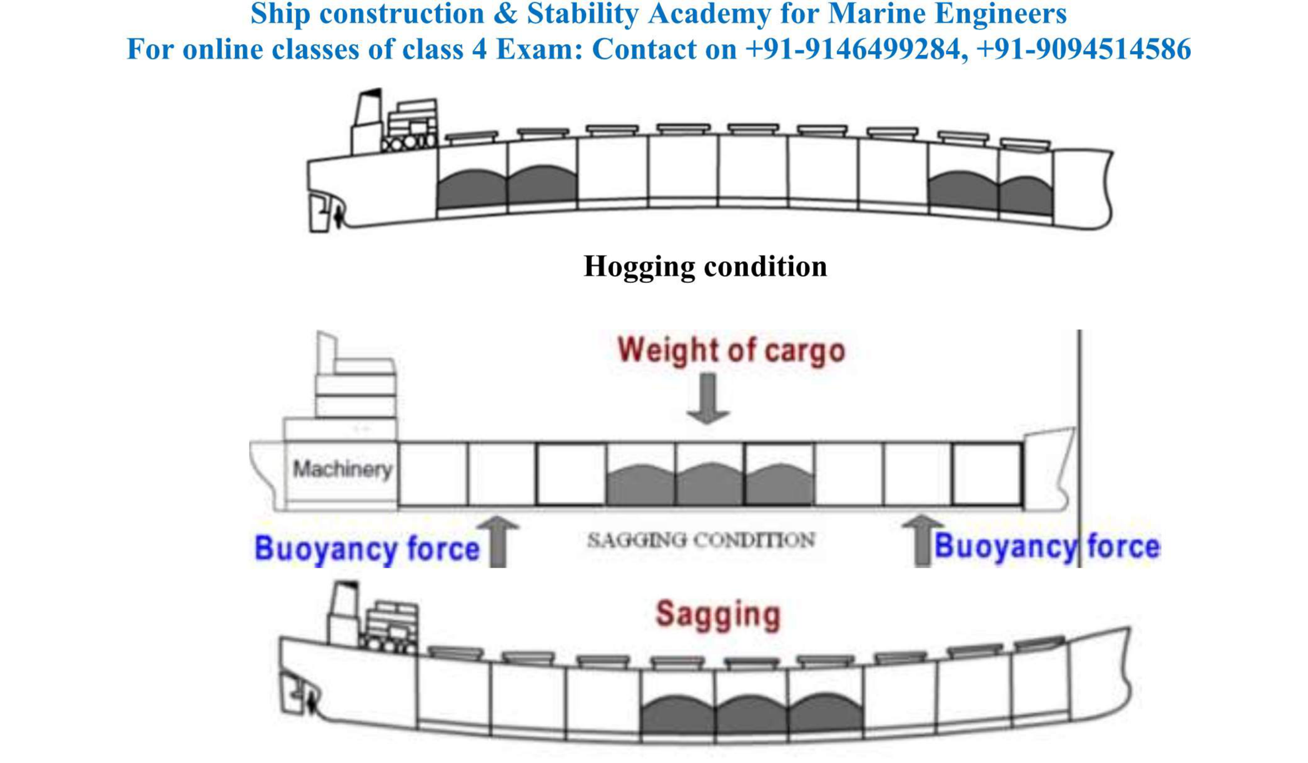
Put the same thing in the oral's own words — if the ship is subjected to local loading at the fore and after ends, the hull tends to hog, and it is worse if the wave crest is at midships; when the wave crests are at the ends of the ship and the wavelength is similar to the ship's length, it is termed sagging.
4.2.4 What resists longitudinal bending
All continuous longitudinal material resists longitudinal stresses. Taken as the list to answer with:
| Member | Contribution |
|---|---|
| Double bottom — centre girder, side girders | Longitudinal strength in the bottom |
| Inner bottom and outer bottom longitudinals | Longitudinal continuity along the bottom |
| Keel and bottom shell | The bottom flange of the girder |
| Tank top plating | Inner flange in a double-bottom ship |
| Side shell at the top — the sheer strake | The upper flange of the girder at the deck edge |
| Deck stringer plates | Upper flange in way of the deck |
| Longitudinal bulkheads, in tankers | Large additional longitudinal strength |
The reason the sheer strake is made 10–20 per cent thicker than the side plating is precisely this one: it is working as the top flange of a girder being bent, and it takes the maximum compressive and tensile stress.
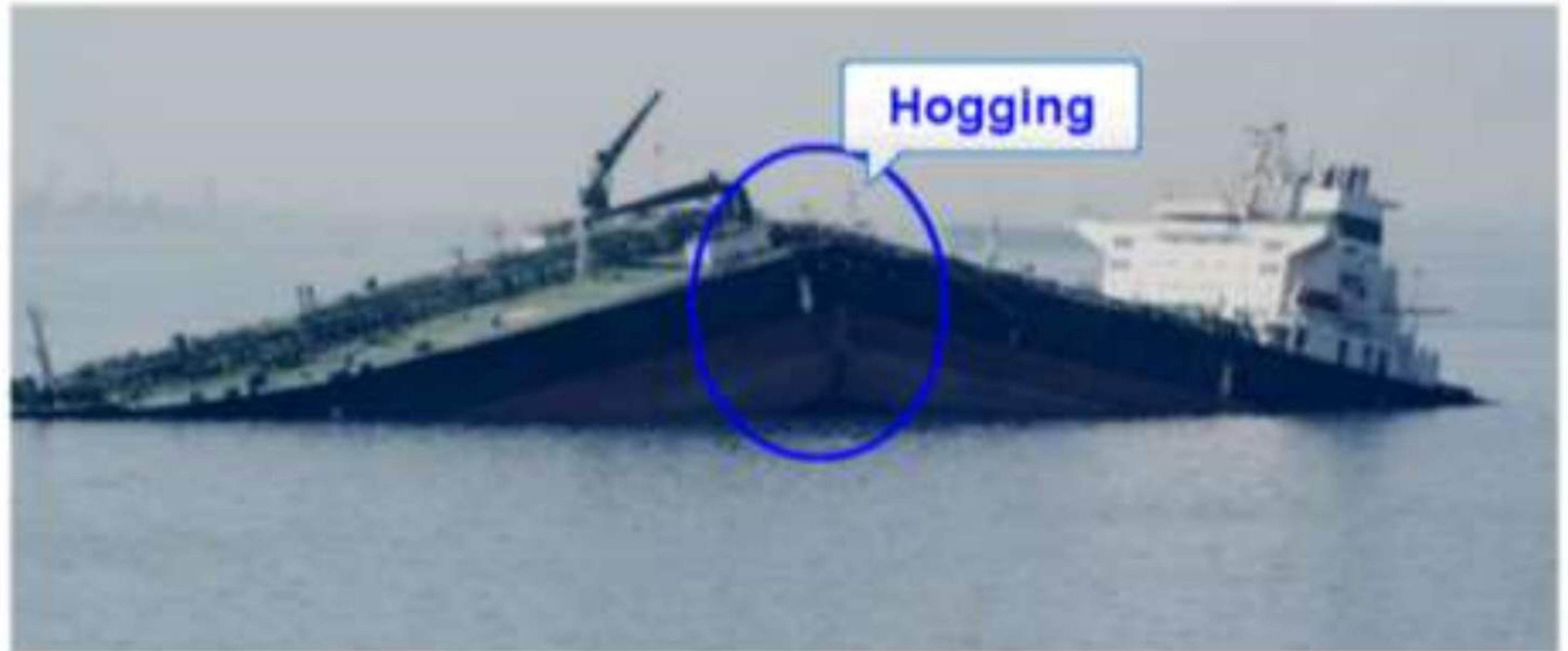
The consequence of the girder being worked this hard is visible in the failures. A tanker that suffered apparent hogging split amidships, with the deck rising to the level of the bridge while the stern and bow remained barely above water. That is a hull girder that reached its bending moment limit at one section.
4.2.5 The combined loading curve and the allowable limits
The bending moment a ship is subjected to is not one curve but several, and the design requirement is that the combined effect of all of them stays inside the allowable limits at every section. The loading instrument presents this directly: it stores the shear force and bending moment at regular intervals along the ship's length for calm harbour and dynamic sea conditions, and it also displays the maximum allowable limits for shear force and bending moment for the various loading conditions.
The output of the instrument, read as the officer reads it:
Shear force and bending moment curves tell the ship's officer that the stresses are within the allowable limits, and that the ship will be able to withstand hogging and sagging, shear force and bending moments, and the other stresses at sea.
The object, then, is not to make the moment small but to keep both curves inside their envelopes for the whole passage — including the ballast condition on the way out and the depleted-bunker condition on arrival, both of which have different distributions from the loaded departure condition.
4.3 The local loadings
4.3.1 The loading instrument
A loading instrument is an instrument, either analog or digital, by means of which it can be easily and quickly ascertained that, at specified read-out points, the still-water bending moments and shear forces in any load or ballast condition do not exceed the specified permissible values.
The loading instrument may also be used to perform stability checks if it incorporates stability software. If stability software is installed on board vessels contracted on or after 1 July 2005, it must cover all stability requirements applicable to the vessel and is to be approved by the classification society.
Most modern cargo ships are equipped with loadicator systems, or a loading computer with appropriate software. It is usually a conveniently sited visual display for the master and the loading officers, and is employed on Ro-Ro vessels, bulk carriers, tankers and other cargo ships.
The main aim of the loading computer is to ensure that the vessel always departs the berth with adequate stability for the voyage. If that situation can be achieved quickly, costly delays are eliminated and the safety criteria are complied with. Ship's personnel can expect to become familiar with the manipulation of the changing variables very quickly alongside the fixed weight distribution throughout the ship: the amounts of bunkers, water and stores are consumed as the voyage proceeds, and the stability data may change for arrival conditions.
Input and output. The data handled by the software falls into three parts:
| Contents | |
|---|---|
| A. Stored data — pre-programmed, because the software is customised to the particular ship | Hydrostatic data: displacement, LCB, LCF, VCB, KMt and MCT against draught. Stability data. Compartment data. Strength calculation data: shear force and bending moment at regular intervals along the length, for calm harbour and dynamic sea conditions, together with the maximum allowable limits for each loading condition |
| B. User input — fed in by the ship's officer | Compartment-wise location, type and amount of cargo, ballast, fuel, fresh water, stores and other weights on board; stowage factor of cargo; density of ballast water and so on, in order to find whether the stability and strength of the ship are within safe limits |
| C. Output — calculated from the stored data and the input, in numerical values and graphical forms such as curves | Hydrostatic data; stability data; compartment data; strength data |
The loadicator output, in the form the officer sees it:
- Shear forces and bending moments affecting the vessel at her state of loading.
- Cargo, ballast and fuel tonnage distributions.
- A statement of the loaded GM, the sailing draughts and the deadweight.
Combine that with what the same instrument gives the officer on the stability side — shifting of cargo, ballasting and de-ballasting, the hogging and sagging condition, shear force and bending moment, and the loading plan — and it is clear why the loadicator is the document that the load line surveyor goes to when he checks that sufficient information is provided on board for loading, discharging, ballasting or de-ballasting.
4.3.2 Racking
Transverse loads tend to change the shape of the vessel's cross-section, and thereby introduce transverse stresses.
When a ship is rolling, the deck tends to move laterally relative to the bottom structure, and the shell on one side tends to move vertically relative to the other. This type of deformation is called racking. It is the dynamic effect of rolling.
The picture-frame comparison is the one that makes it clear: when a ship rolls there is a tendency for her to distort transversely in the same way that a picture frame may collapse.
The mechanism, in detail:
- The angle between a beam and a side frame tends to open on one side and close on the other at the top, and to reverse that action at the bottom.
- Racking stresses due to rolling reach a maximum in a beam sea, each time the vessel completes an oscillation in one direction and is about to return.
- Racking stress also results from the transverse impact of seas.
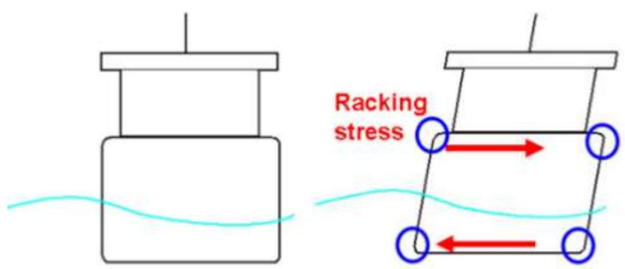
What resists it. The stress comes mainly on the corners of the ship — the tank side brackets and the beam knees — which must be made strong enough to resist it and provide sufficient resistance to this stress.
Taken as the set of resisting members:
| Member | Effect |
|---|---|
| Transverse bulkheads | The greatest effect of all; they primarily resist the transverse deformation |
| Beam knees and tank side brackets | Rack the corners, where the stress concentrates |
| Frames and web frames | Provide very great strength to resist racking |
| The uppermost continuous deck | Closes the top of the box |
The contribution of the side frames by themselves is insignificant, provided the transverse bulkheads are at their usual regular spacings. With the usual spacing of bulkheads and side frames the effect of racking is negligible.
4.3.3 Torsion and the torsion box
Torsion. When any body is subject to a twisting moment — commonly called a torque — that body is said to be in torsion.
A ship heading obliquely, at about 45°, to a wave is subjected to righting moments of opposite direction at her two ends, twisting the hull and putting it in torsion. In most ships these torsional moments and stresses are negligible, but in ships with extremely wide and long deck openings they are significant.
The torsion box. The remedy is a torsion box girder structure including the upper deck, fitted at the topsides. A particular example is the larger container ship, where a heavy torsion box girder structure including the upper deck is provided to accommodate the torsional stresses.
| Item | Specification |
|---|---|
| Location | Runs from the collision bulkhead to the aft peak bulkhead, on both the port and starboard sides |
| Prevents | Torsional bending of the ship due to the torsional moment caused by the dynamic movement of the wave |
| Prevents | The racking effect caused by the shear stress on the vessel |
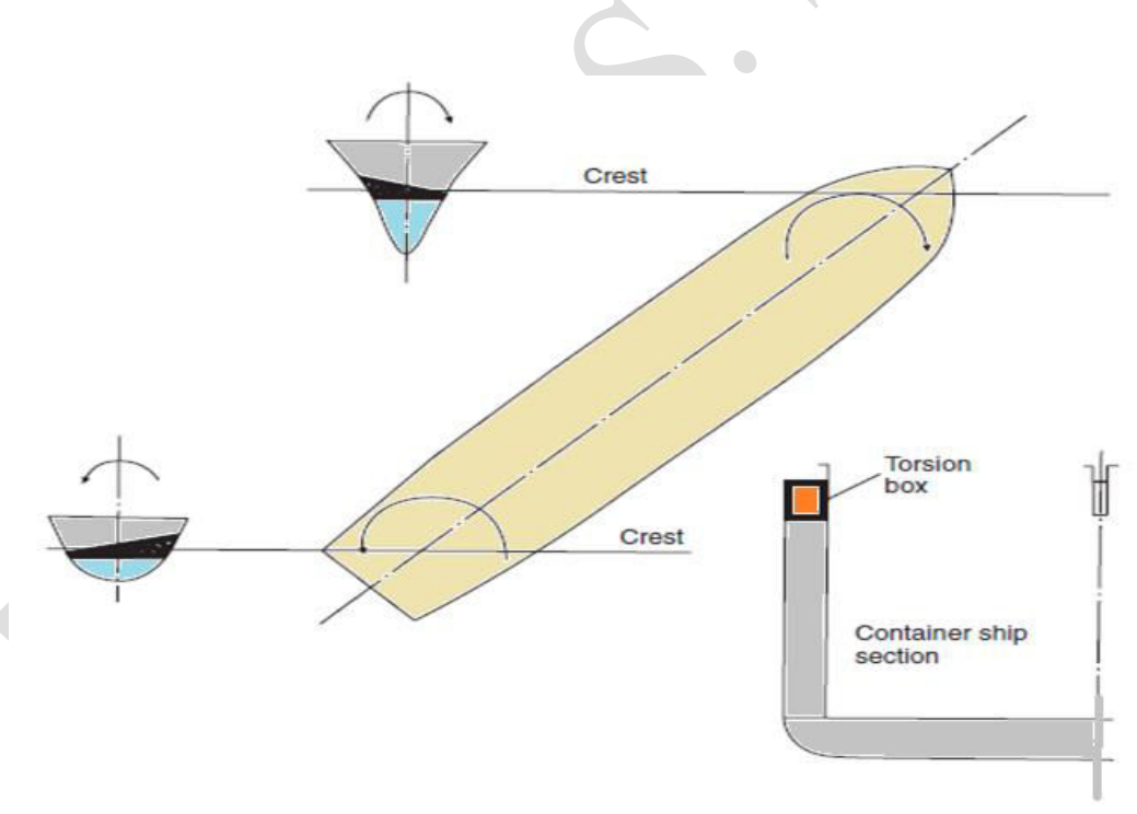
Why a tanker has no torsion box, and a bulk carrier can manage without one.
- An oil tanker has many transverse bulkheads which act as the main stiffening members against racking and twisting, along with the uppermost continuous deck, which has no hatch openings to compare with a dry cargo ship. So an oil tanker does not need the additional stiffening member that is a torsion box.
- A bulk carrier has small hatch openings and sufficient deck space or deck stiffening members to counteract the twisting moment.
- It is the container ship, with its wide deck openings, that has neither of those protections and therefore needs the box.
4.3.4 Panting
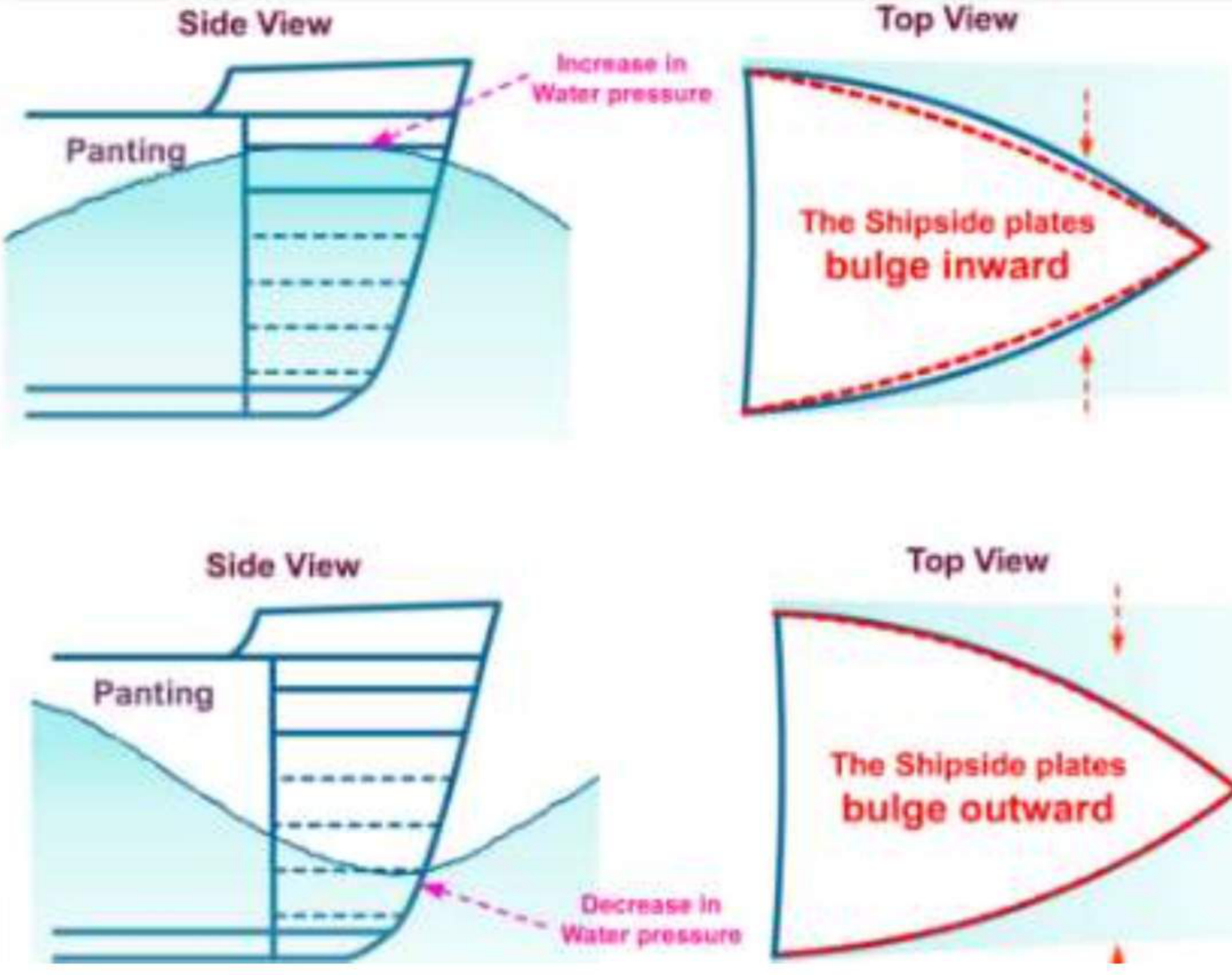
Panting is an in-and-out, bellows-like motion of the plating, caused by fluctuating water pressure as the bow passes through successive waves. Taken a little wider: panting is the contiguous bellowing-in and bellowing-out of the ship's hull plating due to variable water pressure distribution caused by waves, and the effect is accentuated in the forward region when the ship drives headway through. The bow region is the most affected area, because the entire vessel meets the wave systems there for the first time; the dynamic wave pattern has a variable hydrostatic pressure distribution point to point, which falls incongruously on a solid hull plate. Panting is said to exist throughout the entire length of the hull, but the effect dies away as the wave system loses its energy from the bow shoulder onwards.
It is greatest in fine-bowed ships. The reason is that a fine bow presents a relatively flat shell to the pressure fluctuations: the effect is greatest at the ends of the ship, particularly at the fore end, where the shell is relatively flat.
If the movement were unrestricted it could eventually lead to fatigue of the material, and it must therefore be prevented. The structure at the ends of the ship is stiffened to prevent any undue movement of the shell.
Where it applies. The structure is strengthened to resist panting from 15 per cent of the ship's length from forward to the stem, and aft of the after peak bulkhead. The forward region is where it matters, and the after region is the one other place the shell meets the water at a relatively flat angle.
Arrangements to resist panting. Additional stiffening is provided in the fore peak structure, the transverse side framing being supported by any, or a combination, of the following:
| Arrangement | Detail |
|---|---|
| Side stringers | Spaced vertically about 2 m apart, supported by struts or beams fitted at alternate frames |
| Panting beams | Fitted forward of the collision bulkhead, below the lowest deck, on alternate frames, connected to the beam knee |
| Panting beams | Spaced not more than 2 m apart vertically, and supported by pillars |
| Wash bulkhead | A partial wash bulkhead at the ship's centreline, supporting long panting beams |
| Perforated flats | Spaced not more than 2.5 m apart, with the area of perforations not less than 10 per cent of the total area of the flat |
The panting stringers and beams are bracketed to the shell frames; where the panting beams are long they may be supported at the ship's centreline by a partial wash bulkhead, and the intermediate frames are bracketed to the stringer.
The whole arrangement is summarised by its own description: panting stringers are longitudinal stiffening members formed in a closed rounded-triangular shape, with the peak being the fore end, by the side stringers on both sides and the collision bulkhead at its end.
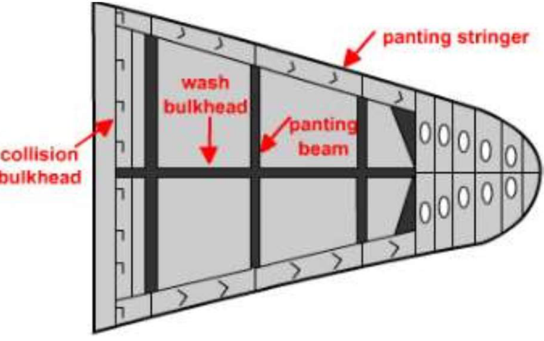
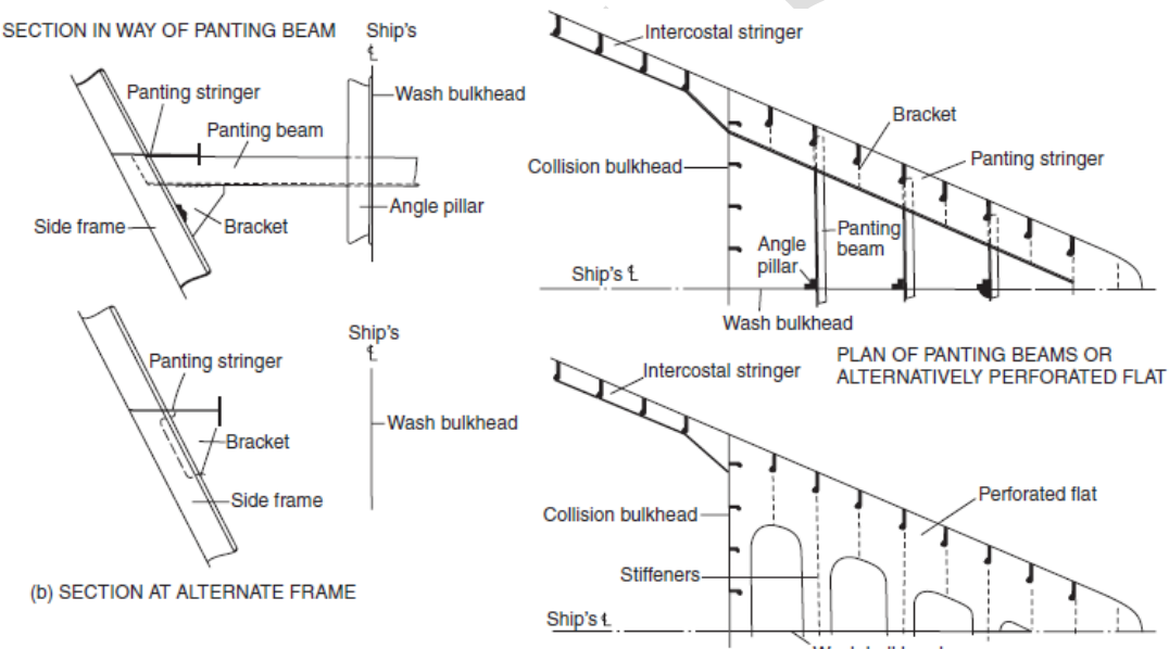
The structural chain forward of the collision bulkhead is worth holding in one line: floor plates at the bottom, stringers running longitudinally along the sides at given intervals, deep radius floors, breast hooks, pillars, angle pillars, panting stringers, panting beams, perforated flats and a centreline wash bulkhead. The designer's freedom is in the deviation of scantlings and positions of this panel-stiffening, not in its presence.
4.3.5 Pounding, or slamming
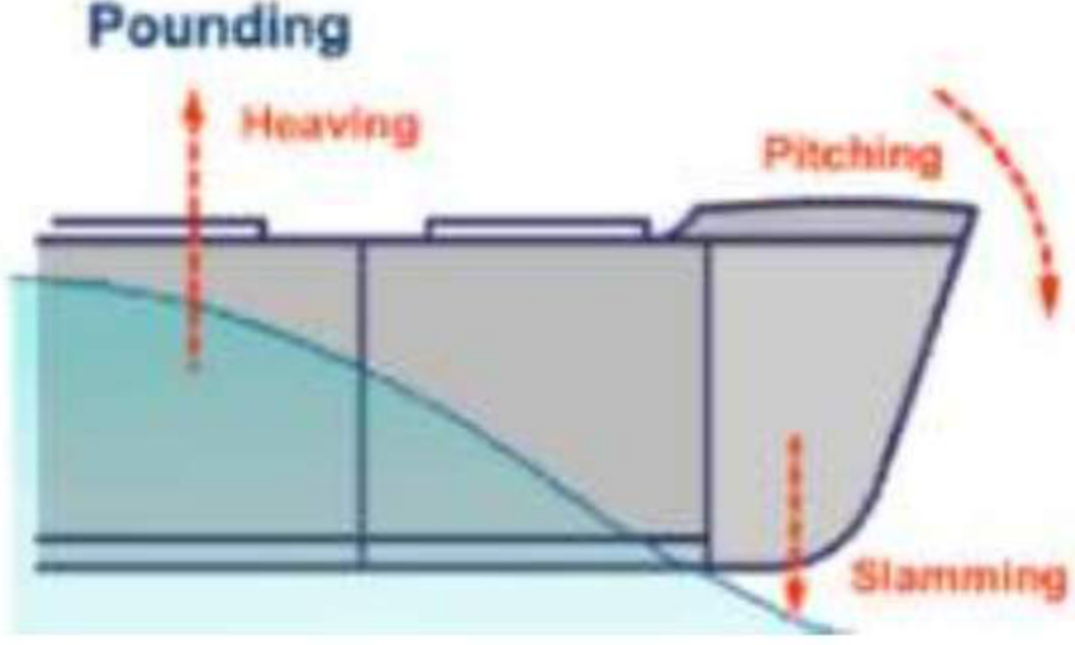
When a ship is pitching, her bows often lift clear of the water and then come down heavily. This is pounding. Severe pounding, with the bow falling into the water violently, is also known as slamming.
Defined as an effect rather than a motion: pounding is the effect resulting from the rise and fall of the forward end of a ship when heaving and pitching. The forward bottom gets the impact of the water surface, whether caused by ship velocity, water velocity, or both.
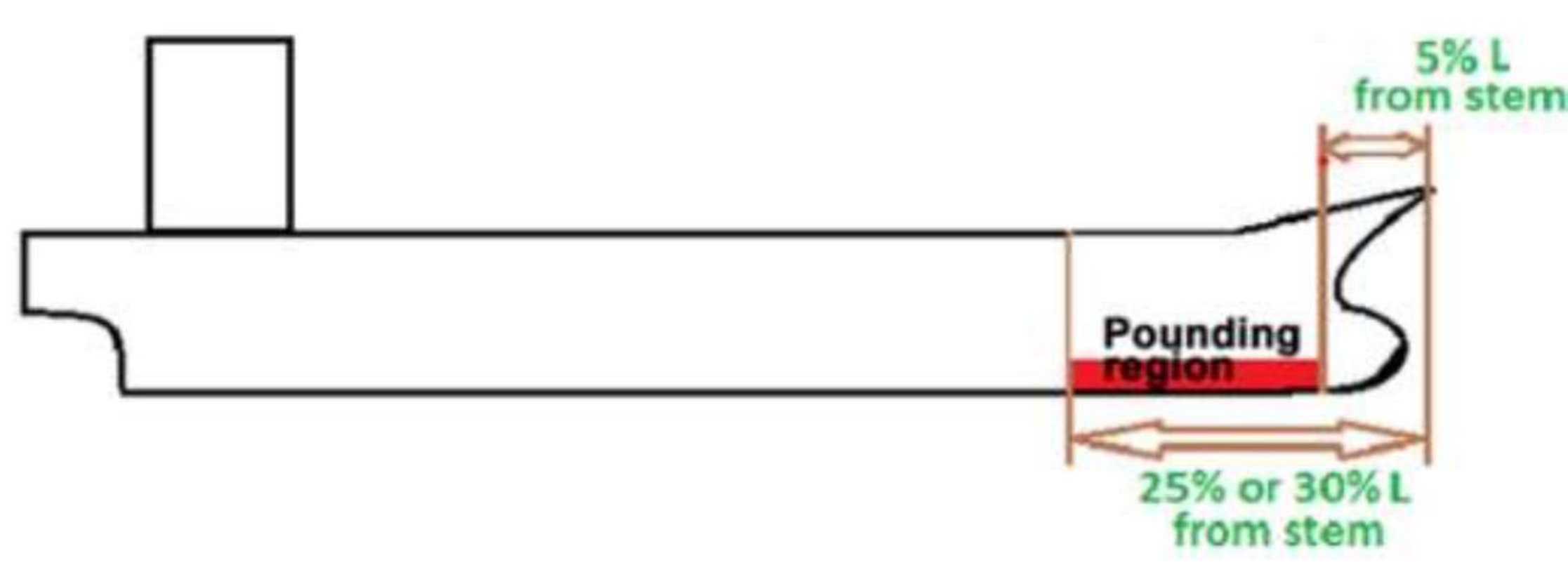
It occurs most in full-bowed ships — the opposite of panting, which is worst in fine bows — and it may cause damage to the bottom plating and girder work between the collision bulkhead and a point about one-quarter of the ship's length from the stem.
These pounding stresses are likely to be most severe in a lightly ballasted condition, and additional stiffening is required in this region. The physical reason is straightforward: in a light condition the forefoot comes clear of the water more easily and comes down harder.
Pounding forces are induced by the slamming motion of the ship, triggered by heaving or high pitching motions. The situation is further aggravated in the case of empty or lightly ballasted conditions. The intense pounding stresses incident on the plating spread over a large area, extending a considerable distance even behind the forward collision bulkhead.
Where it applies. Pounding stresses are to be expected in the ship's bottom between points 5 per cent of the ship's length abaft the stem and 25 per cent of the length abaft the stem, or 30 per cent in some cases. The forward 5 per cent is excluded because the bow sections there are too fine to land flat; the region that matters is the reasonably flat bottom just abaft it.
Stiffening to resist pounding:
| Framing system | Requirement |
|---|---|
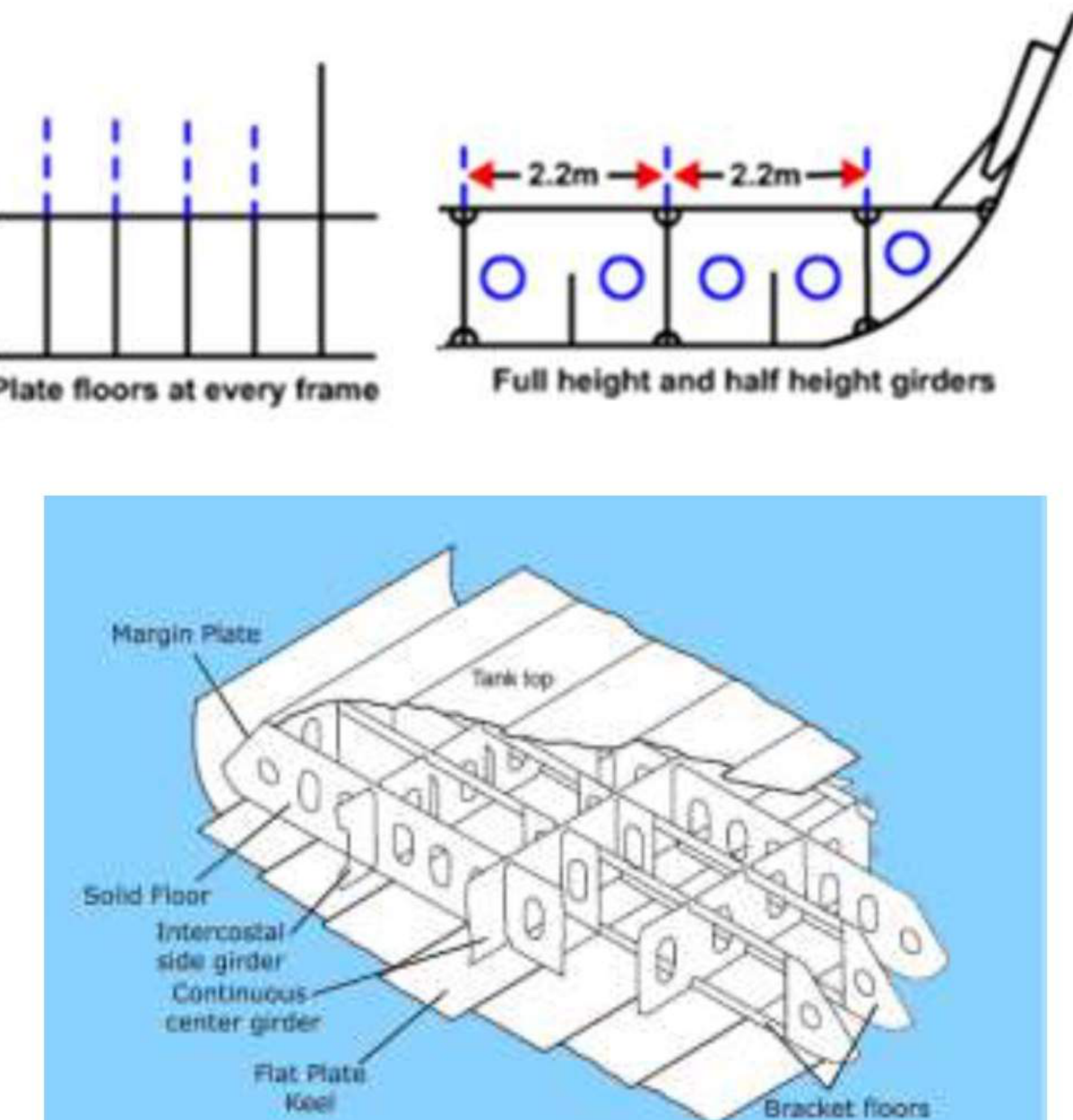
| Transversely-framed bottom | Plate floors fitted at every frame space, connected to the outer bottom plating by continuous welds. Extra intercostal side girders so that the distance between side girders does not exceed 2.2 m; further intercostal side girders of half the depth of the main ones fitted midway between the latter |
| Longitudinally-framed bottom | Plate floors fitted at alternate frames; the longitudinals may have to be stronger than normal; side girders not more than 2.1 m apart |
| Shell plating | The four strakes of shell plating either side of the keel are generally increased in thickness in the pounding region |
| Extent | The forward bottom structure is strengthened for between 25 and 30 per cent of the length |
4.3.6 Whipping and impact loads
Whipping loads are a class of low-cycle, high-frequency stress-inducing loads caused by the slamming motions described above. They are said to be an outcome of impact loads, which are themselves a result of the pounding loads.
What impact loads are. Impact loads act all of a sudden and are of large intensity, in response to the natural structural response of the entire ship's hull. The oncoming waves hitting the fore part of the hull generate a large amount of impact pressure, creating impact loads which in turn generate a pattern of rapid vibrations on the material — and that is what is called whipping.
Impact loads also depend on the relative motion between the vessel and the water surface. For the purposes of design, velocity constraints and surge direction are therefore key determinants of the net effect of impact loads.
How whipping arises, step by step. In rough sea states the bow performs the oscillatory motion described under pounding: the fore bottom floor emerges from the water and then plunges into the sea again. This incessant emergence and impact may spark off a vibration in the hull girder. These high-frequency vibrations cause severe loading on the entire structure, and may sometimes exceed the wave-induced stress and aggravate the situation when both are superimposed.
Whipping is thus a straightforward outcome of slamming, and it can induce higher girder bending moments and fatigue damage to the entire structure of the ship. It is therefore very much wiser to control it beforehand in the fore region rather than allow it to propagate.
The same paragraph names the other end of the problem: vibrations caused by the ship's propeller and machinery aft spark off various unwanted local stresses in the stern. The fore and aft end constructions therefore need special care, because these loads can sometimes lead to massive structural failure.
4.3.7 Green water, or wave slap
The waves encountered by a ship in rough sea states are highly unpredictable. They can reach tremendous heights and, on interacting with the ship's forward end, may lash themselves onto the exposed weather deck. This event is the wave slap, or green water.
The consequence for the structure is not the same as for the others in this section. More than the inner hull arrangements in the fore end, the concentration has to be on the deck strengthening in this case. Green water lands on the deck, so the deck, its beams and its supporting structure are what must be designed for it — a different set of members from the shell stiffening that answers panting and pounding.
4.3.8 Bow-flare, stern and bottom slamming
Slamming is not a single event. The three forms named are bow-flare slamming, stern slamming and bottom slamming. The distinction matters because each attacks a different region and therefore a different set of members:
| Form | Region | Structure chiefly affected |
|---|---|---|
| Bow-flare slamming | The flared shell at the bow, above the waterline | The flare plating and the framing behind it |
| Stern slamming | The after body, when the stern comes down | The counter and the after end structure |
| Bottom slamming | The forward flat of the bottom — the pounding case of §4.3.5 | The bottom plating, plate floors and side girders of the fore end |
4.4 Longitudinal strength and the midship section
4.4.1 The hull girder and the section modulus
The longitudinal strength of the hull girder depends on the section modulus of the midship section. That section modulus in turn depends on the scantlings and layout of the structural members in the midship region.
The word for what the hull is being treated as is worth being precise about: a hull girder is the components of a hull structure that contribute to its strength when subjected to longitudinal and/or transverse bending — the shell plating, decks, inner bottom, longitudinals, bulkheads and girders. The girder is not a member; it is the working section made up of many members, and its section modulus is the sum of their contributions about the neutral axis.
That is the reason the same scantling thickness means different strengths in different places: what counts is the member's distance from the neutral axis, so a plate thickness carried out at the deck or the bottom buys far more bending strength than the same thickness in the middle of the depth. It is also why high tensile steel is used where it is: employed in the more stressed regions of large tankers, container ships and bulk carriers, and often for the deck and bottom regions of larger tankers, it reduces the scantlings of those structural items, which proves advantageous both to the shipbuilder and to the owner.
Shell plating, for its part, forms the watertight skin of the ship, contributes to the longitudinal strength of the structure and resists vertical shear forces. The bottom and side shell plating consist of several flat and curved steel plates butt welded together, and they are of greater length than breadth.
4.4.2 The midship region
The midship region extends one quarter of the length of the ship forward and aft of midships.
Over this midship region the scantlings of the structural members are kept the same. Maximum longitudinal bending moment is experienced by a hull girder within this midship zone. Therefore the midship section plays an important role from the longitudinal strength point of view, and at the same time it depicts the structural layout depending on the type of cargo the ship is going to carry.
The two consequences of holding scantlings constant over a quarter-length forward and a quarter-length aft of amidships are worth stating plainly:
- No stress concentration. If the section changed where the bending moment curve is near its peak, the change of stiffness would set up its own stress concentration at exactly the point where the structure can least afford it.
- A working length rather than a working point. The point of maximum bending moment moves along the ship as the distribution of weight and buoyancy changes — with the wave position, with the trim, and with the loading condition. A region of constant scantlings covers all of those positions, where a single heavily-scanted section would only cover one.
4.4.3 The midship section as a statutory plan
Different types of ship have different midship sections. The structural arrangement and the scantlings are shown in these plans, and they are statutory structural plans which are to be approved by the classification society.
The purpose of the drawing is twofold: it demonstrates the longitudinal strength of the section to the society, and it fixes the arrangement of structure for the shipyard. It is why the midship section of a bulk carrier, a container ship, a tanker and a general cargo ship can be laid side by side and still be recognisably the same subject — the same members doing the same duty, redistributed for a different cargo.
4.5 Vibration
4.5.1 The three classes
Ships' vibration falls into three classes:
- Synchronous or resonance vibration.
- Local vibration.
- Vibration due to external forces.
4.5.2 Synchronous, or resonance, vibration
Every ship's hull has a natural frequency of vibration as a free-free beam, and the hull girder vibrates in two, three and four-node forms as well as in torsion. When the frequency of some exciting force coincides with one of those natural frequencies the vibration builds up to large amplitude — that is the resonance case, and it is the one that produces the most severe effects. Its sources are the propeller and the main machinery, and it is the reason the after end of a ship is arranged as it is: to prevent serious vibration at the after end of the ship there must be adequate aperture between the propeller and the hull, and the after end structure is arranged to reduce vibration stresses, which are a major source of trouble there.
4.5.3 Local vibration
Local vibration is vibration of a part of the structure rather than of the hull girder as a whole — a panel, a stiffener, a mast, a deck house, or an item of machinery on its seatings. It is excited by the machinery and the propeller, and the affected item must have its own natural frequency away from the exciting frequencies to avoid being driven. In the fore and after ends it is the local stresses from this source, combined with whipping, that the end constructions have to be arranged to resist.
4.5.4 Vibration due to external forces
The third class arises from forces outside the ship's own machinery — the loadings imposed on the hull by slamming and by the waves. Whipping is the clearest example: a high-frequency vibration of the entire hull girder excited by the impact of the bow coming down onto the sea, which can induce higher girder bending moments and fatigue damage to the structure of the ship.
4.5.5 Where these loads are dealt with
The consequences of all three classes are seen mainly in the after end, where the propeller and the machinery excite the structure, and in the fore end, where the sea does. Both ends are therefore arranged specially, and the detail of that arrangement belongs with the fore end and the aft end — the design intent, in one line, is to prevent serious vibration at the after end of the ship there must be adequate clearance between the propeller and the hull, and the after end structure is arranged to reduce the vibration stresses, which are a major problem there.