
Marine Propeller, Rudder and Steering Gear
How the ship is driven and turned: pitch, slip and cavitation, the rudder and its stock and bearings, the steering gear behind it, and the trials that prove the whole arrangement.
Key Principles at a Glance 8 points
- Pitch is the distance the propeller would advance in one revolution; theoretical speed is pitch times revolutions, and slip is the shortfall against the distance the ship actually travels.
- Apparent slip compares theoretical speed with ship speed, real slip compares it with the speed of advance through the wake — the two differ by the wake fraction.
- Cavitation is the formation and collapse of vapour cavities where local pressure falls below the vapour pressure, and it pits the blade, wastes power and drives vibration.
- Skew offsets the blade opposite to the direction of rotation to spread the pressure loading through a revolution, which is what quietens a propeller working in a bad wake.
- The rudder stock is sized from the torque and the bending moment on it, not from the blade area alone.
- A jumping stopper limits how far the rudder can lift, and about 2 mm of jumping clearance is left to the stern frame so the vertical force never reaches the steering gear.
- The carrier bearing in the steering compartment carries the weight of the rudder, and wear-down is measured with a trammel against the original mark.
- Steering gear must be proved by the SOLAS tests: main and auxiliary gear, the time to go from hard over to hard over, and the alarms that accompany a failure.
9b.1 Propeller
How the ship is driven and turned: the screw that pushes her, the rudder that turns her, and the steering gear and trials that prove them. Part 9 builds the stern that carries all of this; this part is the machinery hung on it.
9b.1.1 The definitions
Taken as a set, in the order that builds on itself:
| Term | Definition |
|---|---|
| Pitch of the propeller | In one revolution of the shaft, the distance the propeller will move forward |
| Diameter of the propeller | The diameter of the circle or disc cut out by the blade tips |
| Pitch ratio | The face pitch divided by the diameter |
| Theoretical speed (Vt) | The distance the propeller would advance in unit time if working in an unyielding fluid. Thus if the propeller turns N rev/min: Vt = P × N m/min, or Vt = (P × N × 60) / 1852 knots |
| Wake | Water which is in motion at the stern of the ship as a result of the ship's movement — the moving water is known as wake |
| Wake fraction | The ratio of the wake speed to the speed of advance |
| Speed of advance (Va) | The speed of the ship relative to the wake |
| Slip | The difference between the actual distance travelled by a ship and the theoretical distance given by the product of the propeller pitch and the number of revolutions. Usually expressed as a percentage, and it can have a negative value if a current or following wind exists |
| Apparent slip | The propeller works in water, so the ship speed V will normally be less than the theoretical speed; the difference between the two speeds is the apparent slip |
| Real or true slip | The difference between the theoretical speed and the speed of advance |
| Skew | The offset of a propeller blade from the vertical in the plane of rotation; it is always a distance in the direction opposite to rotation |
| Longitudinal centre of flotation (LCF) | The point about which the ship will trim when weights are loaded or discharged. If weight is added at the LCF point, trim will not change, only draught changes |
The relations, written as formulas:
Vt = (P × N × 60) / 1852 (knots)
Real slip = (Vt − Va) / Vt × 100 %
9b.1.2 Apparent slip against real slip
Apparent slip:
Since the propeller works in water, the ship speed will normally be less than the theoretical speed. The difference between the two speeds is known as apparent slip, and is usually expressed as a ratio or percentage of the theoretical speed.
Real or true slip:
This is the difference between the theoretical speed and the speed of advance, expressed as a ratio or percentage of the theoretical speed. The real slip is always positive, and it is dependent on current.
The distinction, stated as the thing being measured:
| Apparent slip | Real slip | |
|---|---|---|
| Measured against | The ship's speed through the water as observed | The speed of advance Va — the speed relative to the wake |
| Formula | Difference between Vt and ship speed V | (Vt − Va) / Vt × 100 % |
| Sign | Can be negative — with a current or following wind | Always positive |
| What it hides | The wake | Nothing |
The apparent slip can go negative because it compares the propeller's theoretical advance to the ship's speed over the ground or through the water as observed, and a following current or wind moves the ship faster than the propeller alone could. The real slip cannot be negative because it compares the propeller's theoretical advance to the speed of advance through the wake — that is, against the water the propeller is actually working in. The difference between the two is the wake fraction: apparent slip is a measurement contaminated by the wake, real slip is the measurement with the wake taken out.
9b.1.3 Skew of a blade
Skew is the offset of a propeller blade from the vertical in the plane of rotation, and it is always a distance in the direction opposite to rotation.
Seen from a different angle:
When we look at the ship's propeller surface from behind, the blade appears to be "skewed" — that is, bent or twisted sideways.
What skew buys:
After years of experimentation, analysis and sea trials, it was observed that aptly skewing a ship propeller nullifies or considerably minimises the extent of unsteady hydrodynamic loading in this flow field. This indirectly has positive effects in reducing resistance due to viscous "drag" effects. It also reduces propeller-induced vibrations: - Reduction in unsteady bearing forces and moments. - Reduction in unsteady pressure forces.
Skew is therefore the propeller designer's answer to the same problem the stern frame's tip clearance answers from the hull side. The after body experiences a non-uniform wake — the water there has been slowed by the hull and is moving at different speeds at different radii and at different clock positions around the disc. A blade entering that field experiences a fluctuating load each revolution, and the fluctuation is what becomes vibration in the structure. Skewing the blade spreads that load out in time, so that one part of the blade is not entering the wake peak at the same instant as the rest.
9b.1.4 Rake and skew of the propeller
Rake:
When the propeller is viewed from the side, the blades are not perpendicular to the surface of the hub. It is "tilted" at an angle, either towards the fore end or the aft end of the ship. This is termed rake. One of the biggest reasons for the rake is allowing higher clearance between the blades and the vicinal hull surface. If the blade tip happens to be very close to the hull plating — which is very prone in the case of no or little raked ones — there is a chance of induced vibration due to ship propeller action.
The sign convention:
| Rake | Direction | Name |
|---|---|---|
| Forward | In the direction of the shaft axis towards the fore end | Negative rake |
| Aft | In the direction of the shaft axis towards the aft end | Positive rake |
Rake against skew, held apart:
| Rake | Skew | |
|---|---|---|
| Seen from | The side | Behind |
| Direction of the offset | Along the shaft axis, fore or aft | In the plane of rotation, opposite to rotation |
| Main purpose | Blade-tip clearance from the hull | Unsteady hydrodynamic loading |
| Also gives | — | Reduced drag, reduced bearing forces and moments, reduced unsteady pressure forces |
Both exist for the same reason and both are stated in the same place: the blade must not work too close to the hull, and it must not be loaded unevenly by the wake. Rake moves the blade away from the hull; skew moves the loading around the disc.
9b.1.5 Contra-rotating propeller (CRP)
Contra-rotating propeller: a propulsion arrangement with two propellers rotating in opposite directions on the same shaft.
The arrangement answers the one loss that a single propeller cannot avoid. A propeller imparts rotation to the water it accelerates — that rotational energy is left behind in the wake and is therefore power spent with no thrust to show for it. A second propeller turning the other way in the same flow recovers part of that rotational energy and turns it into thrust.
9b.1.6 Kort nozzle
A shroud or duct fitted around a propeller in order to increase thrust at low speeds. It is often fitted to tugs and trawlers.
The application follows from the physics: the duct works by accelerating the flow through the propeller disc and by generating its own thrust on the duct itself, and the benefit is greatest at high thrust and low advance speed — which is exactly the bollard-pull condition of a tug and the trawling condition of a trawler. A ship that spends its life at a steady service speed at moderate thrust gains little from a nozzle and pays for it in added resistance.
9b.1.7 Propeller fitting procedure, and how it is secured
The procedure, in order.
1. Check the propeller shaft.
- After removing the old propeller, check that the shaft taper, key and thread are undamaged.
- Try the propeller shaft nut on the shaft thread.
- The shaft taper should be clean and dry.
- Five minutes with a dial indicator while the shaft is still installed can save a lot of agony and expense later. Even a slightly bent shaft will cause trouble; if a dial indicator is not available, rest a pointed stick on the rudder with the pointed end aligned to the machined centre of the shaft, then rotate the shaft — any deviation indicates the tapered end may be bent.
2. Bearing check.
- Before installing the new propeller, ensure that the shaft bearing is not worn.
- A worn bearing or shaft will not be suitable for any propeller, so if it is worn, replace it. If there is too much play of the shaft in the bearing, the bearing must be replaced, or vibration and damage to the shaft can occur.
- Certain types of bearings require some clearance; if not sure, contact the manufacturer and ask what the maximum allowable clearance is.
3. Check key and keyway.
- Check that the key fits the keyway. Ensure the key slides through the new propeller's keyway without jamming at any point, and with no apparent slop.
- It is helpful to mark the direction of the key in the keyway.
4. Propeller fit — the dry fit.
- Dry fit the propeller to the shaft, without the key in place first. Check that the propeller does not rock on the taper.
- Mark the shaft at the forward end of the propeller hub.
5. Fit the propeller to the shaft.
- First fit the new propeller onto the shaft without the key in place and mark the shaft at the forward edge of the propeller hub. Remove the propeller and place the key into the shaft keyway.
- Slide the propeller back onto the shaft and check that the forward edge of the hub comes to the shaft mark.
- If not, it is likely that the key is too large and the propeller is not seated on the shaft taper correctly. Remove the propeller and file the top of the key down until the propeller will slide on to the shaft and reach the mark. This ensures the propeller is correctly seated on the shaft taper.
6. Lap the propeller to the shaft.
- Liberally coat the tapered end of the shaft and the bore of the propeller with fine grinding paste.
- Slide the propeller onto the shaft. Apply gentle pressure and rotate the propeller on the shaft 90° to the right, then 90° to the left, and repeat several times.
- Occasionally remove the propeller and wipe out the grinding compound and visually inspect the bore.
- Continue until a minimum fit of 75 per cent is achieved.
7. Check the propeller position.
- Carefully clean the propeller and the shaft and check the dry fit once more. The propeller will probably go to a different position on the shaft than before — mark this new position.
8. Install the propeller.
- Install the propeller with the key fitted to the shaft. Some prefer a lubricant on the shaft; this is not recommended.
- Check that the propeller goes up to the mark on the shaft. If it does not, the propeller is sitting on the key, and the height of the key must be reduced.
9. Secure the propeller.
Draw the propeller up the taper using the propeller locking nut, then lock this nut with the second nut. Don't forget to fit a new cotter pin.
So the propeller is secured by three separate means, and each has a distinct job:
| Means | Job |
|---|---|
| The taper | Carries the driving torque by friction, once properly seated and lapped |
| The key | A positive back-up for the torque, and the reason the key must not be so tall that it holds the hub off the taper |
| The two nuts and the cotter pin | Hold the hub drawn up the taper; the second nut locks the first, and the cotter pin locks the second |
The dry-fit and key-filing sequence in steps 4–8 exists entirely to protect the taper. A key standing proud of its keyway holds the hub off the taper, the taper then carries no friction and the torque goes onto the key alone — which is not what a key is there for.
9b.1.8 Painting of propellers
Painting your propeller will degrade the performance. Barnacles, on the other hand, will degrade the performance more than properly applied paint. If you use the vessel often, painting is not necessary. If you have the bottom regularly cleaned, painting is also not required. On the other hand, if the vessel is not used as often as you would like, painting may be helpful. A good alternative is the specialised silicon propeller coatings, e.g. Propspeed, which work because they are slick — any marine growth slides off the metal surface when moving through the water.
The procedure:
- The propellers will be clean when received, apart from a light coat of oil. Remove this oil film using alcohol or acetone.
- Choose a good-quality zinc chromate primer and lightly coat the propellers.
- The anti-fouling paint to use on propellers is sold under various trade names as "outdrive anti-fouling paint" in spray cans. Spray 2–3 light even coats, taking care not to get any paint into the bore of the hub.
- Allow at least 48 hours' drying time before putting the propellers into service.
- It is best not to apply standard anti-foul paint with a brush, as it tends to "spin off" the propellers quickly and cannot be applied as evenly as spray paint.
The trade-off is stated fairly in the first line and is easy to get backwards: the paint itself costs performance, but fouling costs more, so the question is only which cost is greater for that vessel's pattern of use. The zinc chromate primer is the part that is doing the corrosion work; the anti-fouling is only the top coat, and the instruction to keep it out of the bore of the hub is because the bore is a fitted surface that must seat dry on the taper of §9b.1.7.
9b.1.9 Propeller position and alignment checks
Alignment check:
After the vessel has been in the water for 24 hours, the engine alignment should be checked.
The delay matches Part 9 §9.4.6 and the reason is the same: the hull takes up its afloat form only once it is floating.
Shaft zinc anode:
Shaft anodes should be fitted as far forward on the shaft as possible, or as near to the cutlass bearing as practical, so that it does not disturb the water flow to the propeller.
The requirement is a small collision between two duties, and the instruction resolves it in favour of the flow. The anode protects the shaft from galvanic corrosion (Part 5 §5.1.5), and it must be in contact with the shaft to do so — but anywhere near the propeller it would be a disturbance in the inflow to the blades, which is exactly what Part 9 §9.1.1 exists to keep smooth. So it goes as far forward as the protection will allow.
Vessel performance record:
Record the vessel's performance after the hull is cleaned and while the propeller is in good condition. Note the top RPM and speeds achieved. This data will be very useful when fine-tuning the propellers and so on.
The point of the record is that it is the baseline. Without a clean-hull, good-propeller measurement, a later loss of speed cannot be attributed between fouling, propeller condition and engine condition, and the diagnosis becomes guesswork.
9b.2 Rudder
9b.2.1 What a rudder is, and how it works
The question that catches people out:
Did you know that a rudder does not turn a ship? … And if not the rudder, then what is it that turns the ship?
The rudder force. Assume a starboard turn — the rudder is moved to the starboard side. When the helmsman changed the rudder angle from zero to some angle towards the starboard, at that very moment a lift force acts on the rudder. The direction of the lift force is towards the port side.
What that force does:
This rudder force is directed along a transverse direction to the ship. In other words, this force will cause the ship to attain a sway velocity towards the port side, because the rudder force is nothing other than a sway force towards the port. It is because of this that a ship will sway slightly to the port when the rudder is turned over to hard starboard. But this sway is so negligible in comparison to the turning moment towards starboard that the sway is hardly felt. But yes, the sway does occur. Other than this, the rudder force creates a moment about the centre of gravity of the ship.
9b.2.2 Sway velocity, surge velocity and drift angle
The rudder does not turn the ship:
Imagine the size of a rudder in comparison to the size of the ship. The rudder is incomparably smaller to the size of the hull that is to be turned by it. … the rudder moment created by the rudder is negligibly small to turn the ship by the required heading angle.
What the rudder moment does instead:
When the rudder moment acts about the ship's centre of gravity, it slightly changes the ship's orientation by giving it a drift angle. This moment is not large enough to turn the ship to the required heading angle, but all a designer has to do is make sure that the rudder moment is enough to introduce a slight drift angle into the ship's movement. The ship, with that drift angle, is now moving along the initial direction — but this isn't pure surge any more. You can make components of the ship's velocity along the surge (longitudinal) direction and the sway (transverse) direction. Thus, by introducing a drift angle, the rudder has introduced a small surge velocity to the ship.
The terminology, defined by what each is:
| Term | What it is |
|---|---|
| Surge velocity | The component of the ship's velocity along the longitudinal direction |
| Sway velocity | The component of the ship's velocity along the transverse direction |
| Drift angle | The angle by which the ship's velocity vector is turned away from the centreline, introduced by the rudder moment |
| Ship's velocity | The resultant of the surge and sway components |
9b.2.3 Inertia force at bow and stern during a turn
Why the sway matters:
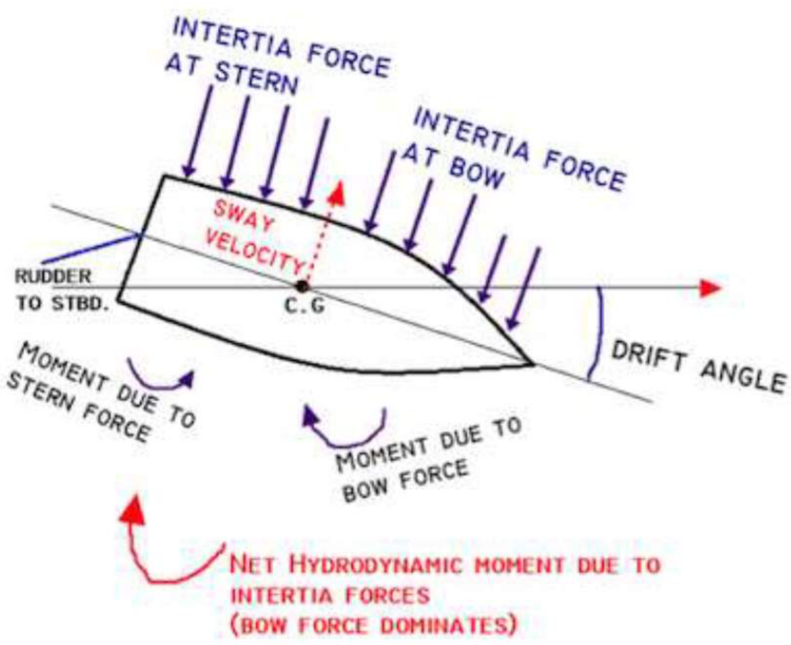
The sway component … is what changes the hydrodynamics around the ship's hull to cause it to turn. With a sway velocity towards the port side, the hull sways towards port. When it does so, it exerts a force on the water particles on its port side. The water particles in turn exert an opposite force on the ship's hull, due to the inherent inertia of the water particles. The direction of this inertia force is always opposite to the sway velocity, since inertia force always opposes motion. So the ship's hull experiences an inertia force in the starboard direction.
Splitting that force in two:
| Component | Moment about the centre of gravity |
|---|---|
| Inertia force at the stern | Creates an anticlockwise (towards port) moment |
| Inertia force at the bow | Creates a clockwise (towards starboard) moment |
Now the hull is designed such that the sway inertia force at the bow is more than that at the stern, therefore the resultant moment is towards the starboard direction.
The magnitude:
When the hull exerts force on the water around it during its sway to port, the inertia force exerted by the water on the hull tries to achieve an equilibrium, which means the magnitude of the inertia force is in the order of the ship's displacement. It is that large a force. So when the resultant hydrodynamic moment acts on the ship, its magnitude is in the order of the ship's displacement. This moment, unlike the moment caused by the rudder force alone, is sufficient to turn the ship.
The conclusion, which is the whole of §9b.2:
This hydrodynamic moment wouldn't have come into play had the ship not attained a drift angle or a sway velocity component, which was mainly due to the action of the rudder. This is enough to justify that the rudder does not turn the ship. It only initiates a drift angle in the ship, which results in a hydrodynamic moment, which is actually the driving force behind the turning action. The hydrodynamic moment is in the same direction as the rudder moment — both trying to turn the ship to starboard. The rudder angle keeps the rudder moment intact, which in turn keeps the hydrodynamic moment intact. Once the rudder is again brought back to midships, first the rudder force vanishes, which results in the diminishing of the rudder moment. It is only after that the drift angle is reduced to zero, and the hydrodynamic moment becomes zero, therefore thwarting the turning action. It is due to this indirect linking of the rudder to the turning action that ships are sluggish when it comes to manoeuvring with rudder action.
The chain, in the form to recite:
Two things in that chain are worth carrying beyond the exam. The bow inertia force must exceed the stern's — that is not an accident but a design requirement, and it is why the after body is shaped as it is. And the order of magnitude is the answer to the natural follow-up question: the hydrodynamic moment comes from the water's inertia resisting the whole displaced mass of the hull, which is why it can turn the ship when a rudder the size of a barn door could not.
9b.2.4 Why the rudder is situated aft of the ship
Four reasons, and the first is the substantial one.
1. The direction of the moment.
The rudder, when turned to starboard, creates a force towards the port. Note the direction of the rudder moment created about the CG — it was towards the starboard, so as to create a drift angle towards the starboard. Now imagine placing the rudder at the ship's bow. Given a starboard angle to the rudder, the rudder force would still be in the port direction. But what about the moment about the CG? The rudder moment would be towards the port, causing a drift angle towards the port, and the net hydrodynamic moment would cause the ship to turn to port — whereas you turned the rudder starboard for a starboard turn.
A rudder at the bow would steer the ship the wrong way, and that is the primary reason. This, and not protection, is the main point: there is another reason — to protect the rudder from collision damage — but this however isn't a primary reason. The primary one is what you just read.
2. The distance from the pivoting point.
The pivoting point of the ship is 1/6 to 1/3 of the length of the ship from the bow. The greater the perpendicular distance between the point of action of the force and the pivoting point, the better the rudder movement.
The ship does not pivot about her centre of gravity but about a point forward of it — one sixth to one third of the length from the bow. Putting the rudder at the stern maximises the lever arm from that pivot, which is the second reason in structural terms.
3. Propeller outflow.
Why is a rudder always placed behind a propeller? The propeller does nothing but increase the velocity of the water that flows out of its slipstream, and the lift generated — the rudder force — is proportional to the velocity of water falling on it. So if a rudder is placed aft of the propeller, the increased velocity of the propeller outflow results in a greater lift force. It is only for this reason that a rudder is placed aft of the propeller. However, if a rudder is placed just forward of the propeller, it will have the same turning effect with respect to direction, but the magnitude won't be the same, given that the flow on the rudder is not as much as it would have been had it been placed behind the propeller slipstream. To make use of propeller outflow for thrust.
4. Protection and drag.
- Better protected at the stern from damage.
- Drag is reduced if the rudder is situated aft.
The four reasons, ranked:
| Rank | Reason | Type |
|---|---|---|
| 1 | A bow rudder would turn the ship the wrong way | Geometry of the moment |
| 2 | Maximum lever arm from the pivoting point (1/6–1/3 L from the bow) | Geometry of the lever |
| 3 | The rudder sits in the propeller slipstream, where the water velocity is highest and the lift force therefore greatest | Hydrodynamics |
| 4 | Protection from collision damage, and reduced drag | Practical |
9b.2.5 The three rudder designs
9b.2.5.1 Spade, or balanced, rudder
Structure:
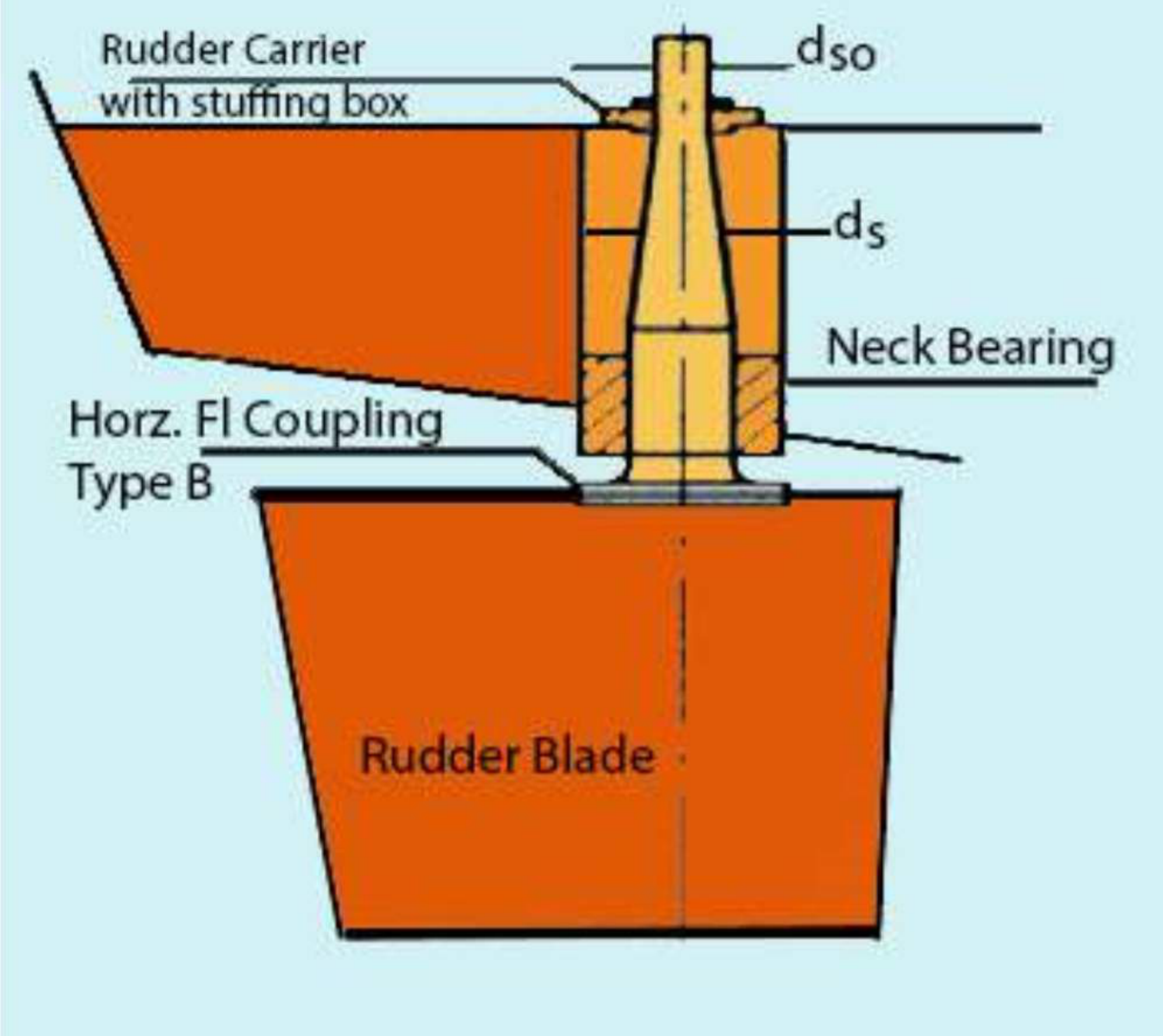
A spade rudder is a rudder plate fixed to the rudder stock only at the top of the rudder. In other words, the rudder stock — the axis of the rudder — doesn't run down along the span of the rudder. The position of the rudder stock along the chord of the rudder — the width, from the forward to the aft end of the rudder — actually decides whether the rudder is balanced or semi-balanced. In balanced rudders, which spade rudders generally are, the rudder stock is at such a position that 40 per cent of the rudder area is forward of the stock and the remaining 60 per cent is aft of it.
Why that position:
The centre of gravity of the rudder will lie somewhere close to 40 per cent of its chord length from its forward end. If the axis of the rudder is placed near to this location, the torque required to rotate the rudder will be much less than what is required to move it had the axis been placed at the forward end of the rudder. So the energy requirement of the steering gear equipment is reduced, therefore lowering the fuel consumption of the ship.
| Item | Detail |
|---|---|
| Stock position | ~40 per cent of the rudder area forward of the stock |
| Bearings | Rudder carrier with stuffing box at the top; neck bearing; horizontal flange coupling; rudder blade below |
| Why balanced | The centre of pressure is close to the axis, so the torque to turn it is small |
| Cost of being balanced | No lower support — the whole rudder hangs on the stock, which is why the stock is fixed only at the top |
The trade is the one to state: a fully balanced rudder needs the least steering effort and has the least structural support, because there is nothing below to hold it. Everything hangs on the stock and the neck bearing.
9b.2.5.2 Unbalanced rudder
Structure:
These rudders have their stocks attached at the forward-most point of their span. Unlike balanced rudders, the rudder stock runs along the chord length of the rudder. The reason: in this case the torque required to turn the rudder is way higher than what is required for a corresponding balanced rudder. So the topmost part of the rudder has to be fixed to the spindle, to prevent it from vertical displacement from its natural position. However, unbalanced rudders are not widely used now.
The older form: a rudder with the whole of its area aft of its stock is called unbalanced. In this, at no angle is the rudder balanced.
How this one is carried:
The unbalanced rudder turns on pintles. The figure shows locking pintles on top and bearing pintles at bottom.
So the two rudder families are carried in two different ways, and that is the structural distinction between them:
| Balanced / spade | Unbalanced | |
|---|---|---|
| Stock position | In the chord, near the centre of pressure | At the forward-most point of the span |
| Carried by | Upper and lower bearings on a fixed axle, or a stock with a carrier bearing only | Pintles and gudgeons |
| Vertical support | Rudder carrier bearing above | Bearing pintle on a hard steel disc below |
| Torque to turn | Low | High |
| In use now | Common | Not widely used now |
9b.2.5.3 Semi-balanced rudder
The problem it solves:
Researchers and ship operators had found significant problems with the balanced and unbalanced rudders. That is, in case there was a failure of the steering gear mechanism while turning a ship, the rudder would remain still with its angle of attack in that condition. The solution to this was found in designing an optimised semi-balanced rudder.
The arrangement:
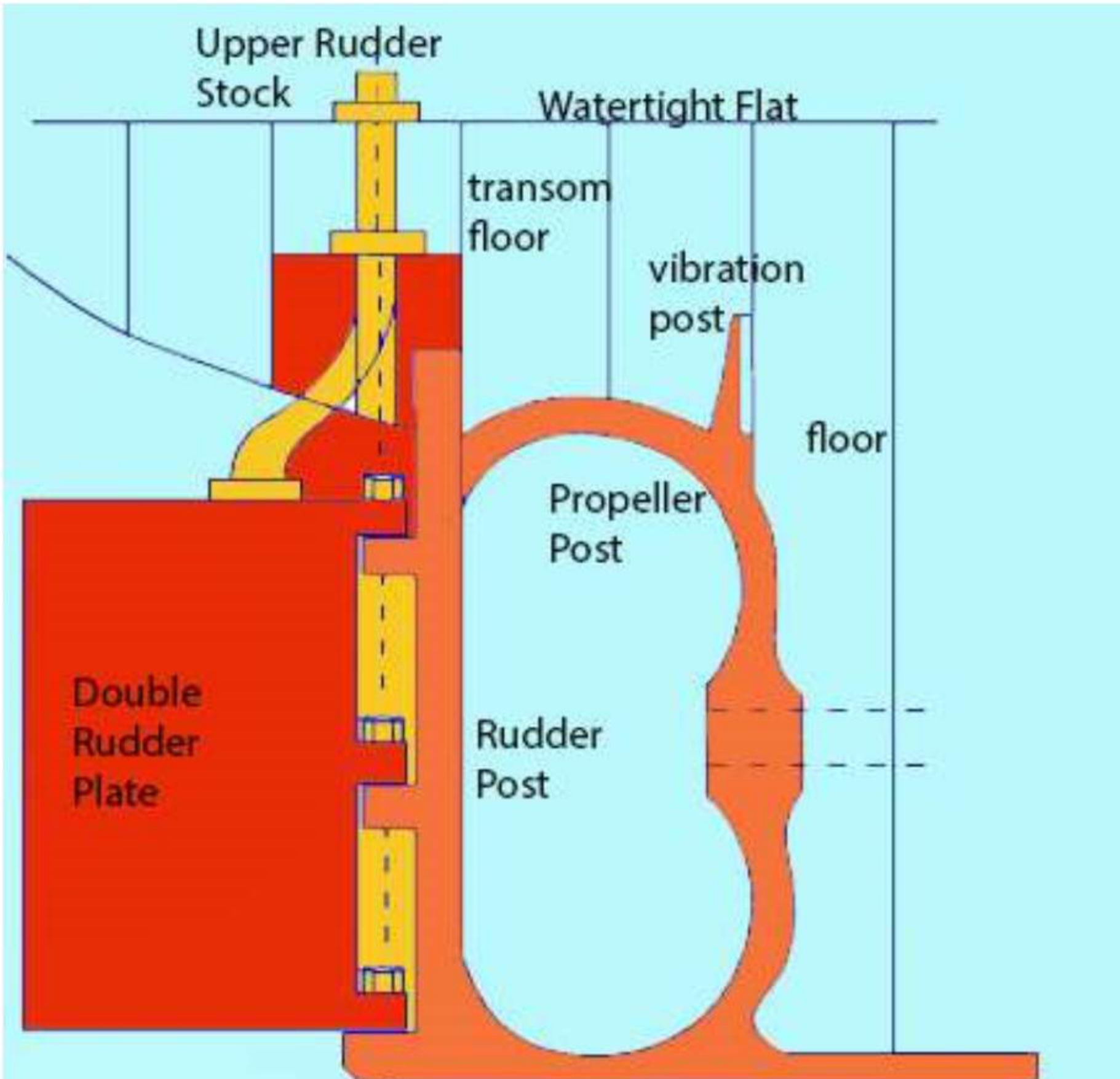
The rudder you see on most ships are semi-balanced in the modern industry. The name semi-balanced itself implies that the rudder is partly balanced and partly unbalanced. A portion of the chord length from the top is unbalanced, and the remaining chord length is balanced. The top part being unbalanced will help in acting as structural support to the rudder from vertical displacement. And the balanced part will render less torque in swinging the rudder. As a result, a semi-balanced rudder returns to the centreline orientation on its own if the steering gear equipment fails during a turn.
| Character | Detail |
|---|---|
| Area distribution | ~20 per cent of the area forward of the stock |
| Where found | Often found in twin-screw ships |
| Balance | At no angle is the rudder balanced — i.e. it is never in full balance |
| Failure behaviour | Returns to the centreline on its own if the steering gear fails |
| Horn types | Shallow horn — extends hardly half the chord length from the top; deep horn — extends up to more than 50 per cent of the chord from the top. The depth affects the response and torque characteristics of the rudder |
That last column is the one to remember and it is the reason the type displaced the other two. The semi-balanced rudder is the only one of the three that fails safe: with the stock at a partly forward position, the resultant hydrodynamic force aft of the axis produces a restoring moment, so a rudder left free returns to amidships instead of staying hard over with the ship turning.
9b.2.6 Which rudder is most used, and how the weight is taken
Semi-balanced rudder is mostly used. The weight of the rudder may be taken by bearing pintles, or by a bearing at the rudder head (rudder carrier), or by a combination of both.
Three possible arrangements, and the choice is settled by the rudder type using them:
| Arrangement | Used by |
|---|---|
| Bearing pintles | The unbalanced rudder, whose bearing pintle at the bottom rests on a hard steel disc in the stern frame |
| Rudder carrier bearing at the rudder head | The balanced rudder, where under normal circumstances the weight of the rudder is taken by the carrier bearing located in the steering compartment |
| A combination of both | Where the lower bearing rings are fitted with a small clearance but may support the weight of the rudder should the carrier bearing fail |
That last case is the redundancy arrangement and it is the most useful one to be able to describe, because it shows the hierarchical logic: the carrier bearing takes the weight in normal service; the lower bearing takes it only if the carrier fails. The lower bearing is deliberately fitted with clearance so that it is not carrying load normally — which is exactly why it can still be intact when called upon.
9b.2.7 How a rudder is constructed
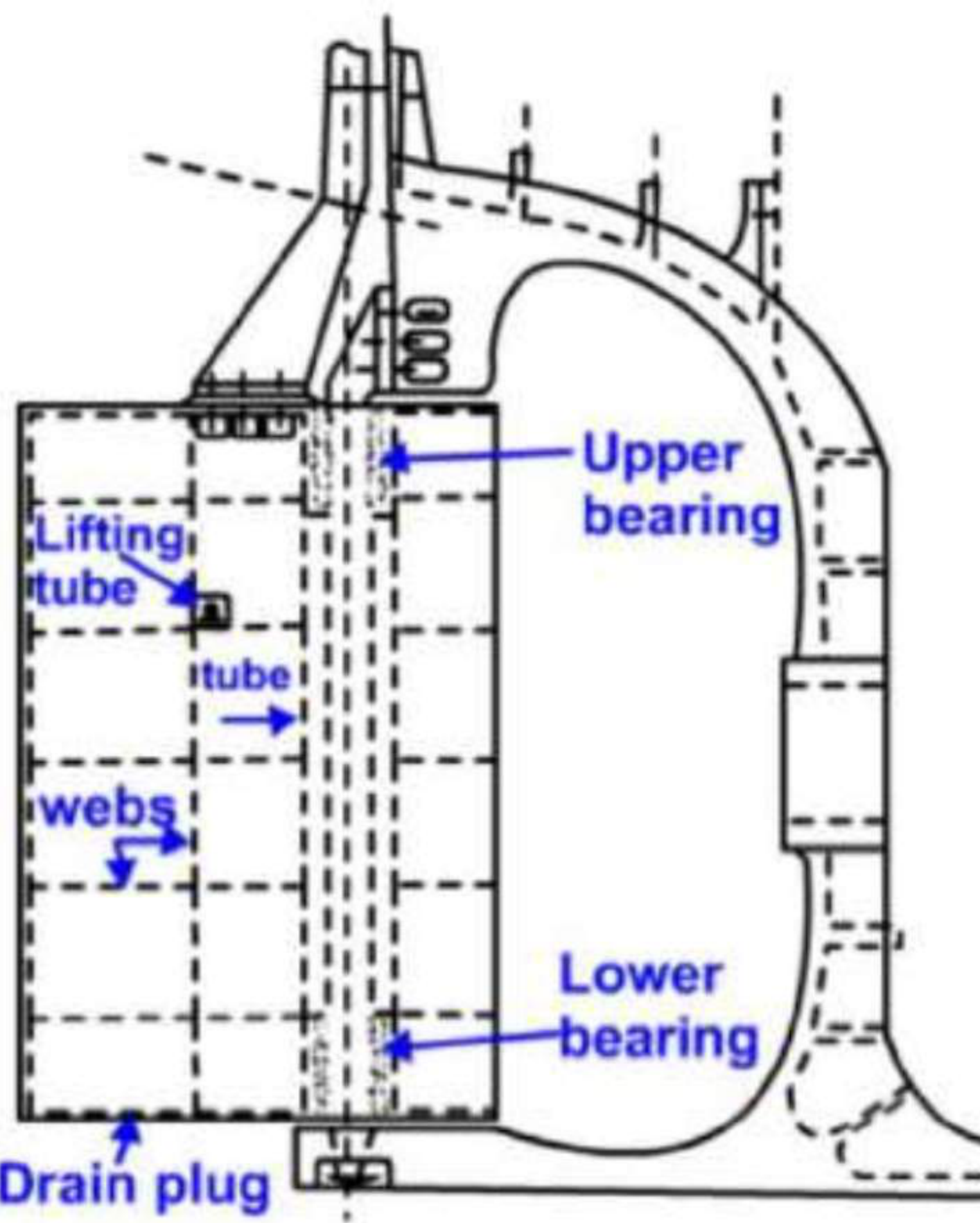
- Rudders fitted on ships are steel structures, adequately strengthened, and so designed and shaped as to withstand the hydrodynamic pressure exerted on them by the sea water.
- Rudders may be of cast or forged steel, or built of web plates welded together on internal frames.
- They may be hinged on pintles and gudgeons, or they may turn about an axle with upper and lower bearings which passes down through the rudder.
- The upper face of the rudder is formed into a, usually horizontal, flat palm which acts as the coupling point for the rudder stock.
- Rudders are hollow, and so provide for some buoyancy.
- In order to minimise the risk of corrosion, internal surfaces are provided with a protective coating, and some are even filled with foam.
- A drain plug is provided to allow for the drainage of water.
- A means of lifting is provided, taking the form of a tube as close to the centre of gravity as possible.
- After manufacture, every rudder is air tested to a pressure equivalent to a head of 2.45 m above the top of the rudder, in order to ensure its watertight integrity.
The hollow construction is doing several jobs at once, and they are worth separating. Hollow means buoyant, which reduces the load the carrier bearing has to take; it means light, which reduces the load the stock has to transmit; and it means the internal structure is a web-and-frame box whose external shape is faired. The price is that the interior is a void exposed to sea water the moment the shell is breached, which is why it needs an internal coating or foam fill, a drain plug to let out what does get in, and the 2.45 m air test to prove it is tight before it goes into service.
9b.2.8 Rudder pintles and bearings
The rudder, depending on its type and arrangement, will turn on either bearings or pintles.
The bearing arrangement on a balanced rudder:
The balanced rudder has a fixed axle fitted at its turning axis. Upper and lower bearings are fitted in the rudder. The upper and lower bearings consist of a bronze or stainless steel cage in the rudder and a bronze or stainless steel liner on the axle. The stainless steel bush is spirally grooved to permit lubrication. A tufnol bush is fitted in the cage and acts as a low-friction bearing material for the rudder. Under normal circumstances the weight of the rudder is taken by the carrier bearing located in the steering compartment. The lower bearing has bearing rings fitted between the rudder and the stern frame. These are fitted with a small clearance, but may support the weight of the rudder should the carrier bearing fail.
Tufnol is the low-friction synthetic bearing material — it appears in every bearing in this part, on the axle, in the cage and on the pintle, and it is the material that makes a rudder that is immersed continuously able to turn without a pumped lubrication system.
The pintle arrangement on an unbalanced rudder:
The figure shows locking pintles on top and bearing pintles at bottom. A pintle consists of a bearing length of constant diameter and a tapered length which is drawn into a similarly tapered hole on the rudder. The pintle is drawn in by a large nut pulling on the threaded portion of the pintle. The pintle nut is securely locked in place after tightening.
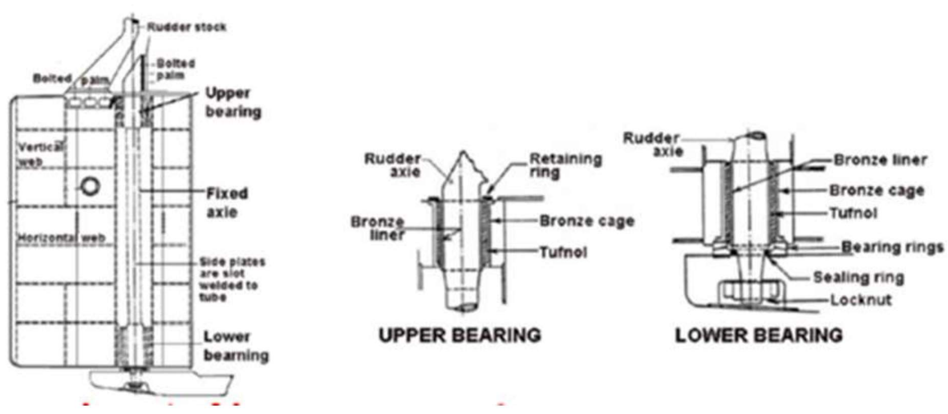
9b.2.9 Locking pintles and bearing pintles
| Pintle | Position | Feature | Duty |
|---|---|---|---|
| Locking pintle | Upper | A shoulder of increased diameter at its lower end | Prevents excessive lift of the rudder |
| Bearing pintle | Bottom | A bearing surface at its lower edge which rests on a hard steel disc | Only required to support the weight of the rudder in the event of the rudder carrier failing |
The two are a matched pair and they answer two different loads. The locking pintle is holding the rudder down; the bearing pintle is holding it up. Since the carrier bearing above is doing the weight-carrying in normal service, the bearing pintle is the standby — the same redundancy arrangement as the balanced rudder's lower bearing, expressed in pintle form.
9b.2.10 The pintle nut, and the prevention of excessive lift
The pintle nut is securely locked in place after tightening.
The nut is the member that draws the tapered pintle into its tapered hole, which is how the pintle is held rigidly in the rudder. The taper is doing the same job here as the shaft taper of §9b.1.7: it takes the load in friction and shear rather than on the nut alone. Once tightened, the nut is locked — and the locking pintle's shoulder of increased diameter is the member that prevents the rudder lifting. That shoulder is what stops the whole rudder being driven up out of its bearings by a sea striking the blade, which is the vertical-load case the whole pintle arrangement exists to resist.
9b.2.11 Rudder stock
A rudder stock may be of cast or forged steel, and its diameter is determined in accordance with the torque and any bending moment it is to withstand.
Where it goes and how it connects:
- The stock passes through the rudder trunk and is connected to the steering gear.
- At its lower end it is connected to the rudder by a horizontal or vertical bolted coupling.
- This coupling enables the rudder to be lifted from the pintles for inspection and service.
Its diameter, defined from the two loads [SC, p. 33 — the same statement made about the rudder in the materials table]:
The stock may be cast or forged steel, with its diameter as determined by the torque and any bending moment it is to withstand.
The two loads are worth naming separately, because they are what the diameter is set by:
| Load | Source |
|---|---|
| Torque | The rudder turning force acting about the stock axis, which is large when the rudder is not balanced |
| Bending moment | The side force on the blade acting through its distance from the stock, transmitted up the stock to the bearing |
The bolted coupling is the feature that makes the whole arrangement serviceable. Because the rudder hangs on pintles or bearings that must be inspected and replaced, and because the stock's bearings are inside the stern, the rudder has to be able to be separated from the stock and dropped or lifted as a unit — which is why the coupling is bolted rather than welded, and why it appears in the survey item list of §9b.2.15.
9b.2.12 Rudder carrier bearing
The rudder stock passes through a watertight seal and a rudder carrier bearing before entering the steering compartment.
Construction and duty:
| Item | Detail |
|---|---|
| Duty | Takes the weight of the rudder on a grease-lubricated thrust face |
| Components | Base cone and moving cone |
| Location of the stock | The stock is located by the journal beneath, also grease lubricated |
| Support | Support for the carrier bearing is provided by framing beneath the steering gear deck, with a doubling plate in the area beneath the carrier bearing |
| Location of the base | The base of the carrier bearing is located by side chocks welded to the deck — wedge-type side chocks welded to the deck stiffening |
| Materials | The carrier is of Meehanite, with a gunmetal thrust ring and bush |
| Removability | Carrier bearing components are split as necessary for removal or replacement |
| Lubrication | Screw-down lubricators are fitted, and the grease used is of a water-resistant type — calcium soap based with graphite |
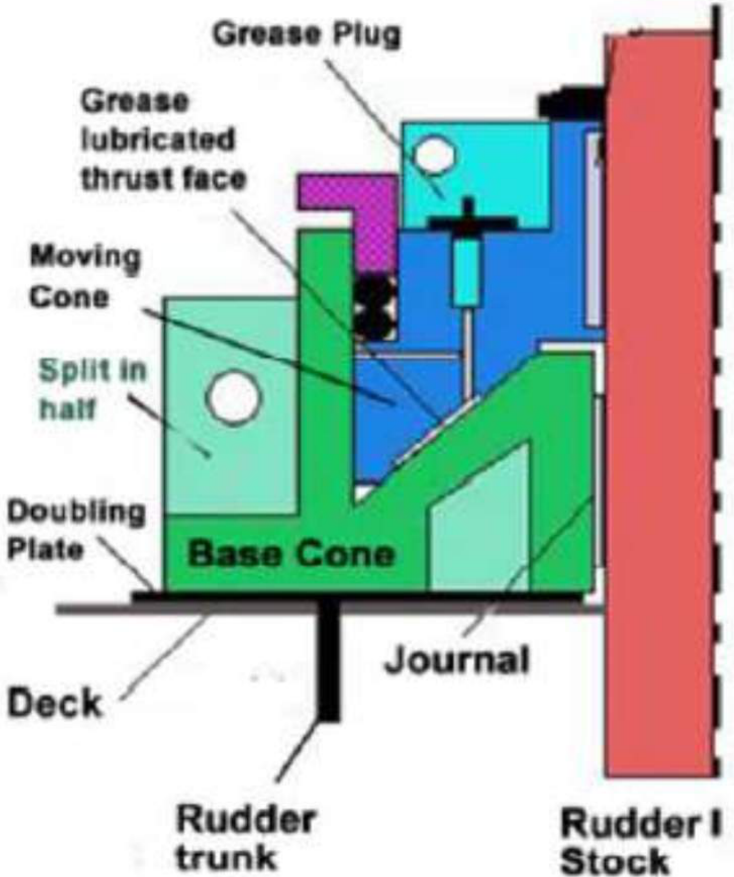
The thrust face is what makes this a bearing of an unusual kind. Every other bearing in the ship in this part — the neck bearing, the lower bearing, the pintles — is resisting rotation. The carrier bearing is resisting a downward load: it is the member that carries the entire dead weight of the rudder and holds it in the steering compartment. That is why it has a base cone and a moving cone rather than a cylindrical bush: the load path is vertical, taken on an inclined face, and spread by the cones into the deck structure below.
9b.2.13 Rudder drop and jumping clearance
Rudder carrier bearing wear-down occurs over a period of time, and allowance is made in the construction of the steering gear for a small vertical drop of the rudder stock. This wear-down allowance is checked periodically with a trammel, and restored as necessary.
How the measurement is made:
This takes the form of an "L"-shaped bar of suitable construction. When the vessel is built, a distinct centre-punch mark is placed onto the rudder stock and onto a suitable location on the vessel's structure. The trammel is manufactured to suit these marks. As the carrier wears, the upper pointer will fall below the centre-punch mark by an amount equal to the wear-down.
The alternative measurement method:
This may be measured either between pads welded on top of the rudder and onto the rudder horn, or between the top of the rudder stock and a fixed mark on the inner structure of the steering gear flat.
At sea and at docking — the two sets of limits:
| Condition | Measurement | Where measured | Limit |
|---|---|---|---|
| At sea (ram-type steering gear) | Jumping, or bouncing, clearance | Between the swivel block and the upper ram fork end | 19 mm |
| At sea | Wear-down clearance | Between the swivel block and the bottom ram fork end | 12–19 mm |
| At docking | Bouncing clearance | Between the top of the rudder and the jumping bar | — |
| At docking | Wear-down clearance | Between the bottom of the rudder and a reference mark | — |
The jumping stopper and clearance:
If the rudder is lifted when the ship is underway, due to wave impact or contact with floating objects or bottom contact, the steering gear may be damaged. To prevent such damage, a jumping stopper is provided at the stern frame. The clearance between the stern frame and the rudder is referred to as the jumping clearance. It is about 2 mm maximum. The clearance between the rudder and the flat should be less than the steering gear cross-head clearance. Any vertical force on the rudder will hence be transmitted to the stern frame through the jumping stopper, and not to the steering gear.
The logic in that last sentence is the whole point and it is a deliberate hierarchy of stiffness. The rudder will be lifted at some point — a sea, a floating object, the bottom. The question is only what takes the load when it happens. The design answers it by making the jumping clearance the smallest clearance in the chain: the rudder rises about 2 mm and then lands on the stern frame, so the structure that feels the force is the stern frame, which is built to take it, rather than the steering gear cross-head, which is not.
The rudder stops complete the arrangement:
The rudder is prevented from jumping by rudder stops welded onto the stern frame. These limits refer to rudders of traditional design and are governed by both the physical layout of the rudder and actuator, but also by the stall angles of the rudder — that is, the angle at which lift (turning moment) is reduced or lost with increasing angle of attack. There are designs of rudder such as the Becker flap which have increased stall angles up to 45°.
That last part is the answer to the natural question of why rudder angles stop at 35°. It is not the structure that sets the limit; it is stall. Beyond a certain angle of attack the flow separates from the rudder and the lift force falls away, so turning the rudder further produces more drag and less turning moment. The Becker flap is the device that delays that separation — which is why it can be used up to 45°.
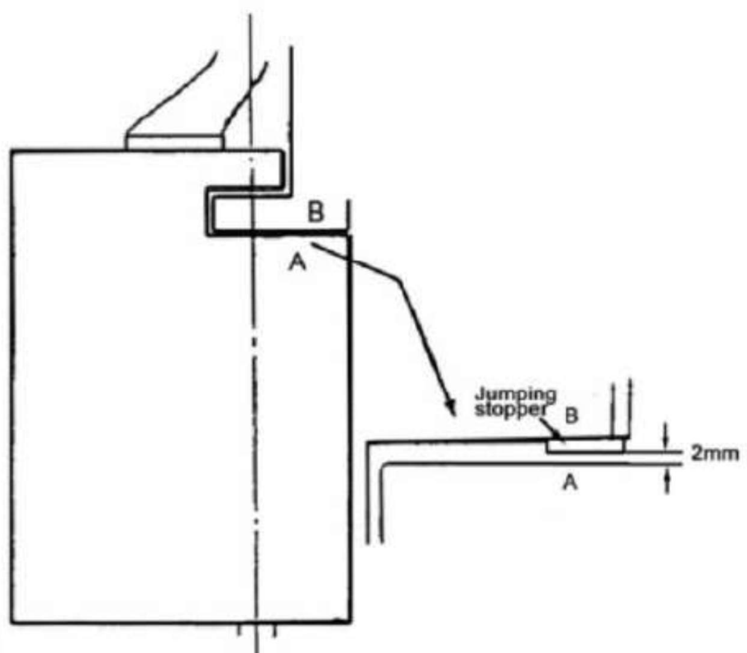
9b.2.14 Jumping clearance and wear-down clearance measured
Both measurements are made at two different places, depending on whether the ship is at sea or in dock, and the pairs in §9b.2.13 give the reason. At sea the surveyor cannot get to the rudder, so he measures the clearances he can reach — at the steering gear, between the swivel block and the ram fork ends. At docking the rudder itself is accessible, so he measures the clearances directly — between the top of the rudder and the jumping bar, and between the bottom of the rudder and a reference mark.
The remarkable thing in the table is the magnitudes. A jumping clearance of 19 mm measured at the ram corresponds to a 2 mm clearance at the rudder itself. The reason is the same lever geometry as everywhere else in this part: the ram is at the end of a long arm from the rudder stock, so a small movement at the rudder becomes a large movement at the ram. The sea-going measurement is a convenient proxy, not the real quantity.
9b.2.15 Rudder trunk
Rudder stocks are carried in the rudder trunk, which as a rule is not made watertight at its lower end, but a watertight gland is fitted at the top of the trunk at the rudder carrier bearing, where the stock enters the intact hull.
The arrangement is worth stating as the deliberate design it is. The trunk is a tube running from the rudder up through the shell of the aft peak into the steering compartment. At its lower end it is not watertight — sea water is allowed in, and the trunk is therefore full of water to the level of the surrounding sea. At its upper end it has a watertight gland, at the rudder carrier bearing, where the stock enters the intact hull.
Building it that way means only one seal has to be maintained, at a place that is inside the ship and reachable, and it means the trunk is not a pressure vessel. If both ends were sealed, a failed lower seal would leave a void that could pressurise, and there would be two things to maintain instead of one. The combination of the carrier bearing and the gland is what the drawing shows as the combined rudder carrier and stuffing box.
The inspection of the trunk is the transom space of Part 9 §9.3.7 — entered in port only, and in calm weather or sea.
9b.2.16 Rudder inspection
The inspection, as carried out in dry dock:
- When the ship enters dry dock and the water is pumped out, check whether water is coming out from the rudder or not. If yes, then the rudder is breached.
- Open the top and bottom plugs and check for any water inside.
- Pressure test the rudder at a water head of 2.46 metres.
- If the rudder is badly rusted or the ship is older, the surveyor may insist on thickness gauging of the rudder plate.
- Check the condition of the sacrificial anode on the rudder.
- Check the cement on the coupling bolts for the rudder and rudder stock. Remove the cement and check the condition of the palm nut.
- Check the rudder pintle clearance.
- Check the rudder jumping clearance.
- Check the rudder drop.
- Check the rudder by hammer test with the surveyor's hammer, tapping on the rudder to evaluate the plate condition.
- Check the actual position of the rudder against the rudder angle indicator, and see whether any difference is there due to bending or deformation.
- Carry out a visual inspection.
The list reads in the order a surveyor would actually work, and the sequence has its own logic:
- The first item is free. Water weeping out of the rudder as the dock drains tells the surveyor whether the rudder is breached before he has climbed into it — the same trick as reading the draught marks as the ship settles.
- Then the direct check, by opening the top and bottom plugs to let any contained water out, and then sealing it and pressure-testing it.
- Then the condition of the material — thickness gauging and the hammer test, which between them answer whether the plate is still there and still attached.
- Then the bearing clearances — pintle, jumping and drop, the three measurements of §§9b.2.13–9.6.14.
- Then alignment, by comparing the actual rudder position with the rudder angle indicator. A rudder that has bent or deformed will read a different angle from the one the indicator shows, and this is the check that catches a bent stock.
- And the sacrificial anode, which is the same item as everywhere else in the ship: the designed point of corrosion, which must be replaced so that it stays the designed point of corrosion.
9b.3 Steering and manoeuvring
9b.3.1 Steering gear requirements
The main steering gear and rudder stock:
- Must be of adequate strength and capable of steering the ship at maximum ahead service speed.
- Must be capable of putting the rudder over from 35° on one side to 35° on the other side, with the ship at its deepest sea-going draught and running ahead at maximum ahead service speed; and, under the same conditions, from 35° on either side to 30° on the other side in not more than 28 seconds.
- Must be so designed that they will not be damaged at maximum astern speed.
The auxiliary steering gear:
- Must be of adequate strength and capable of steering the ship at navigable speed, and of being brought speedily into action in an emergency.
- Must be capable of putting the rudder over from 15° on one side to 15° on the other in not more than 60 seconds, with the ship at its deepest sea-going draught and running ahead at one half of the maximum ahead service speed, or 7 knots, whichever is the greater.
The power unit rule:
In every tanker, chemical tanker or gas carrier of 10,000 gross tons and upwards, and in every ship of 70,000 gross tons and upwards, the main steering gear shall comprise two or more identical power units.
The general requirement:
Every ship shall be provided with a main steering gear and an auxiliary steering gear. The failure of one of them will not render the other one inoperative. Relief valves shall be fitted to any part of the hydraulic system.
Read across, those clauses are one idea applied at four levels of redundancy: two gears so that either alone can steer; two or more identical power units for the largest ships, so that a single unit failure does not take out the main gear; relief valves so that the hydraulic system cannot be over-pressured by a sea on the rudder; and the 28-second and 60-second times as the measurable proof that the sizing is adequate.
9b.3.2 Follow-up and non-follow-up steering, and hunting gear
Non-follow-up system:
When the steering gear is set to the required position, the rudder is moved; and when the rudder reaches the required position, the steering gear must be set to the off position. This system uses the three-solenoid valve.
Follow-up system:
When the steering gear is set to the required position, the rudder is moved; and when the rudder reaches the set position, the steering gear still remains at that position. This system uses the hunting gear arrangement.
Hunting gear:
It is a feedback mechanism of the steering gear which repositions the floating lever of the hydraulic pump as the tiller moves to the desired position.
The distinction, stated as what the helmsman has to do:
| Non-follow-up | Follow-up | |
|---|---|---|
| Helmsman's action | Holds the control over until the rudder reaches the angle, then returns it to off | Moves the control to the angle wanted, and leaves it there |
| Feedback | None | Hunting gear |
| Component | Three-solenoid valve | Hunting gear, floating lever |
| Helmsman's skill needed | High — he is the feedback loop | Low |
The hunting gear is the feedback loop that the non-follow-up system lacks. In the non-follow-up system the helmsman is himself the control loop: he watches the indicator, moves the rudder, and stops it. In the follow-up system the hunting gear repositions the floating lever of the pump as the tiller moves, which is what closes the loop — the pump is driven back to its neutral position by the rudder's own movement, so the rudder stops when it reaches the ordered angle. This is the same distinction as open loop and closed loop in steering-gear terms.
9b.3.3 Safeties of the steering gear
Taken as the set:
- Relief valve for excess pressure
- Short circuit trip
- Hunting gear
- Buffer spring as a shock absorber
- Angle-adjusting stop — hand-over position limit switch
- Double shock valve
- Relief valve
- Hydraulic oil tank level alarm
- Overload alarm
- 200 per cent insulation
Three of those deserve their own line, because they are the ones that answer "what happens when the sea hits the rudder".
The buffer spring absorbs:
- The difference between the steering order speeds and the follow-up speed.
- The movement of the steering wheel if it is mishandled when the hydraulic pump is stopped in.
- The movement of the control lever when the rudder drifts.
- The vibration and shocks from the rudder.
So the buffer spring is the member that stands between the rudder and the control gear, and its function is to let the rudder move without moving the controls. When a sea strikes the blade, the rudder is driven; the spring absorbs that movement so that the shock does not travel back down the linkage to the pump, the telemotor or the wheel.
The angle-adjusting stop, or hand-over position limit switch, is the upper limit on rudder angle — the member that stops the steering gear driving the rudder past its designed travel.
200 per cent insulation is the electrical safety on the motor circuits, meaning the insulation is rated to twice the working voltage.
Daily checks in the steering gear room:
- Pressure gauge of the steering pump.
- Motor amperes on the steering switchboard, and the motor's hand-touch feeling for temperature.
- Noise and vibration.
- Oil level in the tank.
- Oil leakage in the system.
- Grease in the rudder carrier bearing.
- The bottom seal gland, whether good or not.
The list is worth reading as a set of proxies for the whole system: pressure and amperes are the load; touch, noise and vibration are the condition of the machinery; oil level and leakage are the hydraulics; and the grease in the rudder carrier bearing and the bottom seal gland are the two aft-end items that connect the steering compartment back to §9b.2.12 and §9b.2.15.
And the tests before departure:
- Steering gear should be checked at least one hour prior to departure.
- Telemotor transmitter oil level to be checked.
- Oil level of the actuating system tank checked and replenished if necessary.
- Rudder carrier bearing and bottom sea gland checked and greased.
- Start pumps and check the response of the gear.
- Check load-carrying and running of the gear.
Emergency steering drills: every voyage, once at least within three months, and at survey.
9b.3.4 The main steering gear and rudder stock requirements — 35° to 35°
The numbers from §9b.3.1 are worth holding as a table, because they are the statutory ones:
| Requirement | Value |
|---|---|
| Main gear: rudder angle | 35° one side to 35° the other |
| Main gear: time | 28 seconds maximum, from 35° to 30° the other side, at deepest sea-going draught and maximum ahead speed |
| Main gear: strength | Adequate for maximum ahead service speed, and not damaged at maximum astern speed |
| Auxiliary gear: rudder angle | 15° one side to 15° the other |
| Auxiliary gear: time | 60 seconds maximum |
| Auxiliary gear: condition | Deepest sea-going draught, one half of maximum ahead service speed or 7 knots, whichever is greater |
| Two identical power units | Tankers, chemical tankers and gas carriers of 10,000 GT and upwards; all ships of 70,000 GT and upwards |
The 35° is not arbitrary and it is not structural. As §9b.2.13 has it, the limit is the stall angle — beyond it, lift falls away and more rudder angle produces more drag rather than more turning moment. The 15° for the auxiliary gear is a speed compromise: the standby gear is sized for navigable speed, not for the full sea speed the main gear is designed against.
9b.3.5 Buffer spring and its purpose
The buffer spring is fitted to the steering gear to absorb the movement of the rudder so that it is not transmitted to the steering control. Its four functions are listed in §9b.3.3, and the common thread is worth stating:
| Absorbs | Why it matters |
|---|---|
| The difference between steering order speeds and follow-up speed | The rudder follows at a rate different from the rate ordered, and the discrepancy must go somewhere |
| The movement of the steering wheel if mishandled when the pump is stopped | Protects the control linkage from an operator input that cannot be followed |
| The movement of the control lever when the rudder drifts | Isolates a drifting rudder from the control |
| The vibration and shocks from the rudder | The sea load on the blade must not reach the control gear |
The buffer spring is therefore the same kind of member as the jumping stopper of §9b.2.13 and the ground bar of Part 6 §6.7.6: a deliberately compliant or deliberately weak element placed in a load path so that a large force arrives somewhere harmless instead of somewhere expensive.
9b.3.6 Turning circle
Definitions:
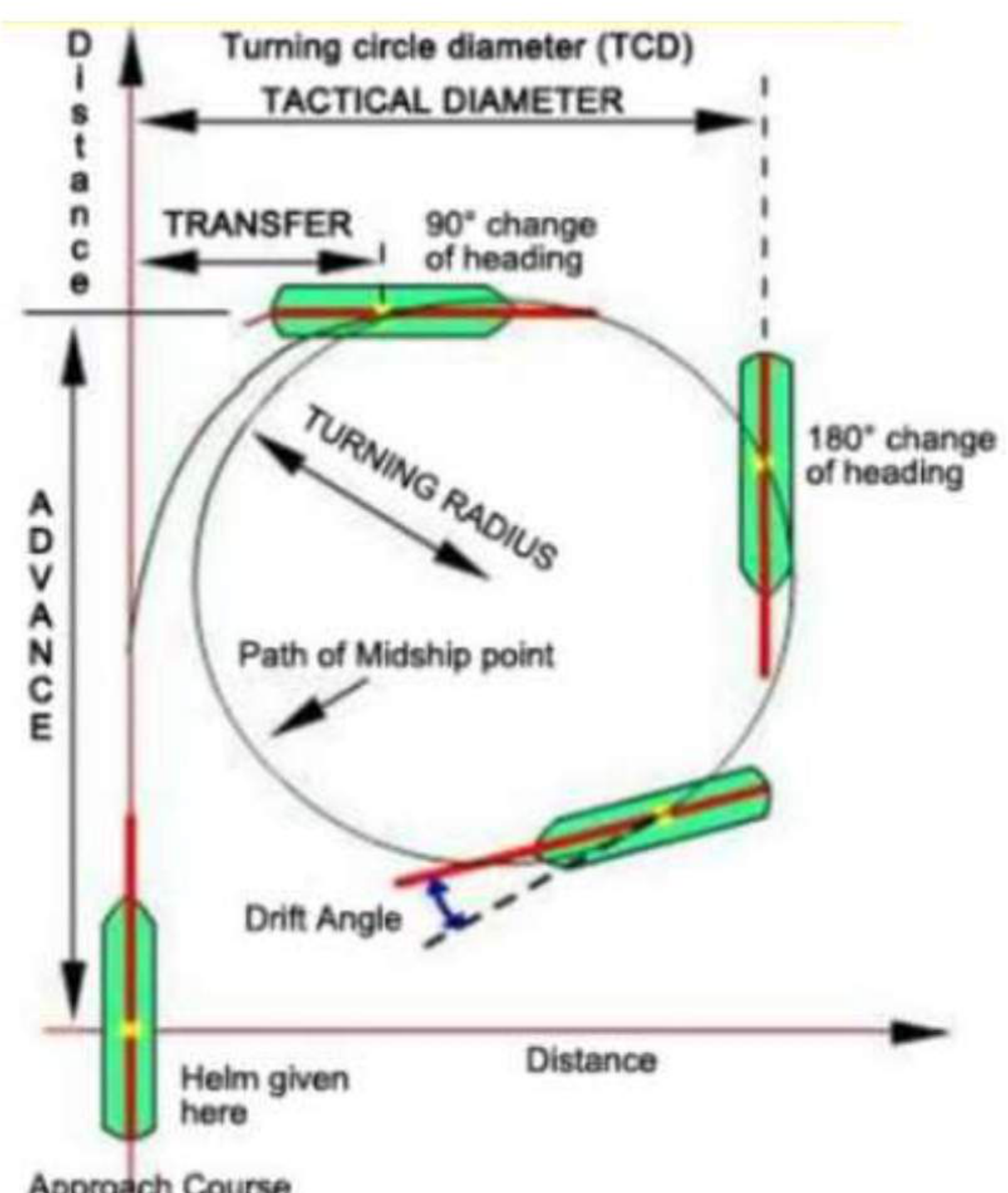
| Term | Definition |
|---|---|
| Turning circle | A circle moved through by a ship when the rudder is placed in its extreme position. It is a manoeuvre carried out on sea trial |
| Turning circle diameter (TCD) | The diameter of that circle, also called the tactical diameter |
| Transfer | The distance the ship moves in the original direction of travel, measured at a stated angle of heading change |
| Advance | The distance the ship moves in the original direction of travel until the heading has changed 90° |
| Drift angle | The angle between the ship's heading and the direction of her actual travel, throughout the turn |
The typical ship and the rudder's influence:
Merchant ships usually turn in a circle having a diameter of about 3–4 times the length between perpendiculars (LBP). The larger the rudder, the smaller will be the turning circle diameter (TCD), also called tactical diameter. During the TCD manoeuvre the ship will experience transfer, advance and drift angles.
How the trial is run:
Turning circle tests are for initial turning and steady turning ability of the vessel. Turning circle trials are carried out at full and half full power RPMs, with the rudder at 35° port or starboard angle. The plotted circle data is framed and exhibited in the wheelhouse as per the IMO requirements. There will be two TCDs of different diameters. This is due to the direction of the rotation of the propeller.
The last sentence is the one that usually needs explaining, and the reason is in §9b.2: the propeller imparts a rotational velocity to the water in the slipstream, and the rudder sits in that slipstream. A right-handed propeller therefore presents a different flow to the rudder in a starboard turn than in a port turn, which makes the two turning circles measurably different. It is also why the ship has a tendency to turn one way when the rudder is amidships.
9b.3.7 Advance and transfer from the turning trial
The recorded trial data:
Normal Full Loaded Condition, with maximum rudder angle. Full sea speed, 104 rpm.
| Item | Port turn | Starboard turn |
|---|---|---|
| Transfer diameter | 0.411 nautical miles | 0.54 nautical miles |
| Advance | 0.388 nautical miles | 0.373 nautical miles |
And the speeds recorded with the heading changes: 16.9 knots, 17.0 knots, 11.5 knots, 12.2 knots, 9.7 knots, 11.34 knots at successive angles, with the Port and Starboard radii both given as 25.52 knots.
The distinction to keep is between the advance and the transfer:
- Advance is measured along the original course, up to the point where the heading has changed 90°. It is the answer to "how far forward will she go before she is broadside-on?"
- Transfer is measured across the original course, and the transfer diameter is the maximum sideways displacement from that course. It is the answer to "how far to the side will she go?"
Both are needed in shallow water and in a channel, and they are what the wheelhouse poster exists to make available in an emergency, when the officer has to know whether the ship can turn inside the space available without running the calculation.
9b.3.8 Change of heading angle test, 20°/20°
The zig-zag test and its purpose:
Zig-zag test is for checking change in head angle, and course-keeping ability of the vessel, according to IMO guidelines. Two tests are conducted — the 10°/10° and the 20°/20° tests. Rudder is turned alternately to either side. In response to rudder, the ship should then turn to port or starboard. This is indicated by changing head angle in response to rudder angle.
The trial name is its own definition: 20°/20° means the rudder is put over 20° one way, and when the ship's heading has changed by 20° the rudder is reversed. The measured quantity is not how fast the ship turns — it is how much overshoot there is past the ordered heading before the ship answers the opposite rudder.
That is why the test is about course-keeping and why it belongs with §9b.2.3. The result measures the lag in the turning chain: the rudder produces a drift angle, and the drift angle produces the hydrodynamic moment, and the hydrodynamic moment turns the ship. A ship with a long lag overshoots, and a ship that overshoots cannot hold a course without continual rudder movement — which is drag, and fuel, and work for the helmsman.
9b.3.9 Turning circle data posted in the wheelhouse
The plotted circle data is framed and exhibited in the wheelhouse, as per the IMO requirements .
The poster exists because the numbers are needed in the moment and under pressure. The IMO requirement is for the turning circle data and the 20°/20° zig-zag data to be available on the bridge, and the reason is practical rather than administrative: an officer handling the ship in a confined channel, approaching a berth or avoiding a collision needs the advance and the transfer of his own ship in a form he can read in seconds, and no officer can reproduce a sea trial from memory.
9b.3.10 Crash stop and head reach
The crash-stop trial:
This test demonstrates the emergency stopping ability of the vessel. The "crash-stop" or "crash-astern" manoeuvre is mainly a test of engine functioning and propeller reversal. The stopping distance of the vessel is recorded. This is called head reach. The distance travelled by a ship, in the direction of the approach path, before coming to rest after having executed a crash stop manoeuvre from a steady, straight-line motion ahead — it is also called headreach.
The track reach — the length of the track including any sheering away from the approach path — is distinguished from the head reach in the same figure. The distinction is the same one as advance against transfer: head reach is how far the ship travels along the approach path; track reach is the length of the actual path, which is longer because the propeller's reversal makes the ship sheer.
9b.4 Summary — what drives and turns the ship
| Load or duty | Fails by | Where it acts | What answers it |
|---|---|---|---|
| Propeller thrust | The shaft being pushed bodily forward | The stern tube and the thrust block | Thrust block in the engine room; the tube as a bearing and a watertight boundary |
| Rudder side force | Bending of the stock, wear of the bearings | The blade, the stock, the pintles, the stern frame | Stock diameter from torque and bending moment; pintles or bearings on tufnol; jumping stopper to keep the vertical force out of the steering gear |
| Sea on the rudder | The rudder lifting, or the steering gear being shocked | The pintles and the buffer spring | Locking pintle with its shoulder; 2 mm jumping clearance to the stern frame; buffer spring in the gear |
| Propeller-induced vibration | Fatigue in the after body | The shell around the aperture | Tip clearance that largely dictates the stern frame size; blade skew; blade rake |
| Rudder weight | The rudder dropping, the carrier wearing | The carrier bearing in the steering compartment | Carrier bearing on a grease-lubricated thrust face; lower bearing as standby; wear-down measured with a trammel |