
Double Bottom Structure and Bottom Framing
The foundation of the ship: transverse against longitudinal framing, then the floors, girders, tank top and keels that make the bottom the most heavily worked part of the hull.
Key Principles at a Glance 8 points
- The bottom answers two opposite loads: cargo weight pressing down on the tank top when loaded, and external hydrostatic pressure pressing up on the shell at deep draught.
- Longitudinals run fore and aft and add to the hull girder section modulus; plate floors run athwartships and carry water pressure from the shell to the tank top.
- A bracket floor is the light form of the floor, fitted between the plate floors where full strength is not needed.
- The centre girder supports the whole bottom structure, the keel plate and the garboard strake; intercostal side girders break the span of the plate floors, one per side up to 20 m of breadth and two per side above it.
- The margin plate closes the double bottom outboard at the bilge at about 45 degrees, and it is the watertight boundary of the tank.
- The tank top is the upper flange of the double bottom, and it is at once a cargo platform, a tank boundary and a strength member.
- A duct keel is a watertight centreline pipe tunnel carrying ballast and fuel lines clear of the cargo holds, while a bar keel is a solid bar projecting below the shell for grounding protection.
- Bilge keels damp roll by working in the boundary layer, and they are welded to a sacrificial ground bar rather than the shell so that a grounding tears the fin off without breaching the hull.
6.1 The framing systems
The foundation. The framing systems come first, because they decide what every other member in this part is doing; then the members themselves; then the openings cut in them; then the keels, which are where the bottom meets the sea.
6.1.1 Why the bottom structure must be stiffened, and to what
One of the most integral parts of the ship is her bottom structure. It is designed not only to give the hull the required strength to withstand the weight of the cargo, but also to withstand the external hydrostatic loads that act on the bottom of the hull.
Those two loads pull in opposite directions and they are the reason the bottom is the most heavily worked part of the structure:
| Load | Direction | Worst condition |
|---|---|---|
| Cargo weight | Downward, onto the tank top | Loaded |
| External hydrostatic pressure | Upward, onto the shell | Deep draught |
A ship's hull is basically made up of bent plates welded together. If these plates are not stiffened, the bending moments on the plates due to the loads may exceed the value of stress that can be withstood by the material, and hence cause failure. So the plates are stiffened — or their section modulus is increased — by adding stiffeners to them.
That is the whole argument for stiffening, and it is the argument of Part 5 §5.2 restated for the bottom: thickening the plate would also do it, but at the cost of the ship's light weight.
There are two basic ways to stiffen a ship:
- Transverse stiffening, or transverse framing.
- Longitudinal stiffening, or longitudinal framing.
6.1.2 Transverse stiffening, and the 120 m limit
Transverse stiffening is carried out in ships less than 120 metres in length. In transverse stiffening, the stiffeners run along the breadth of the ship — that is, athwartships.
6.1.3 Longitudinal stiffening, and why it is used above 120 m
Longitudinal framing employs stiffeners that run longitudinally, that is along the length of the ship, and is used in all seagoing ships having a length more than 120 metres.
Why the 120 m line exists. The answer lies in the fact that ships longer than 120 metres are subjected to high global longitudinal bending stresses like hogging and sagging in different load conditions, unlike smaller ships. So if longer ships were stiffened transversely, the transverse stiffeners would have no role in taking up the longitudinal bending stresses of the hull girder, and therefore lead to more chances of failure. Hence stiffeners are aligned longitudinally in longer ships.
The reasoning is worth holding as a piece of logic rather than a rule of thumb, because it is the question the oral actually wants:
- A long hull is a girder, and in a seaway it is bent lengthwise by hogging and sagging (Part 4).
- A stiffener resists bending in the direction of its depth. A transverse stiffener's depth is vertical, so it resists bending across the ship's breadth — it is working against the local water pressure on the shell, which is what a short ship mostly has to resist.
- A stiffener running along the ship has its depth vertical too, but it is continuous in the fore-and-aft direction, so it adds directly to the section modulus of the hull girder. It is working against the lengthwise bending.
- Therefore, in a ship long enough for lengthwise bending to dominate, transverse stiffeners would be carrying almost none of the governing load.
The rule follows exactly: it is not that transverse framing is weak, it is that in a long ship it is stiffening against the wrong load.
6.1.4 The four bottom structures, and the one that does not exist
The two framings and the one-or-two bottoms give four combinations, and it is worth listing them because the two classifications are mixed together when a bottom is actually designed:
- Transversely framed, single bottom.
- Transversely framed, double bottom.
- Longitudinally framed, single bottom.
- Longitudinally framed, double bottom.
Out of these four types, three are used, and one is not. The one that does not exist is number 3 — longitudinally framed single bottom.
The reason is a chain of logic rather than a rule:
- Since longer ships have longitudinal stiffening...
-...and since longer ships are also designed to carry a higher amount of cargo... -...a double bottom is necessary for them.
So a ship long enough to need longitudinal framing is a ship that needs a double bottom, and the combination "longitudinal framing with a single bottom" has no ship to sit in. It is the neatest example in this part of how two independent design decisions turn out to be linked.
6.1.5 Framing in the engine room of a tanker
Double bottom heights often increase in way of engine rooms, because they need to take up higher stresses due to the heavy machinery in those regions. In the engine room region, all the frames are provided with plate floors, and no bracket floors are used.
There is, however, another factor the designer must take care of when providing an increased double bottom height in a high-stress region. The height must not be increased abruptly, because that would result in a discontinuity, which would lead to concentration of stresses, and eventually a structural failure. The increase in height should be gradually tapered up and down. The taper should start a few frames forward of the engine room bulkhead, and continue up to three or four frames aft of the engine room, to allow proper stress flow or structural continuity.
The machinery space has its own set of requirements on top of that:
- The main engine seating is in general integral with the double bottom structure, and the inner bottom in way of the engine foundation has a substantially increased thickness of about 40 mm, and is continuous to the thrust block seating.
- In the machinery spaces, forces of a pulsating nature are transmitted through the structure due to the general out-of-balance forces of machinery parts, so additional transverse floors and longitudinal intercostal side girders are provided to support the machinery effectively and to ensure rigidity of the structure.
- Machinery is often built up on seatings forming longitudinal bearers, supported transversely by tripping brackets in line with the double bottom floors, the longitudinal bearers being in line with the double bottom side girders.
- Boiler bearers are similarly fabricated, with support from transverse brackets and longitudinal members.
- In motor ships, where a drain tank is required under the machinery, a cofferdam is fitted, giving access to the holding-down bolts and isolating the drain tank from the remainder of the double bottom tanks.
- Additional longitudinal girders are fitted in way of heavy auxiliary machinery such as a generator.
The point running through the list is that in the engine room the bottom structure stops being only a tank boundary and becomes part of the machinery foundation: the loads are pulsating rather than static, they are concentrated rather than distributed, and the structure is arranged to pass them into the shell along lines rather than over a panel.
6.1.6 Frame spacing, with the worked figures
In the main body of the ship, frame spacing may not exceed 1 metre between the collision bulkhead and a point one fifth of the ship's length abaft the stem. It must not exceed 700 mm in peak tanks and cruiser sterns; and in those positions it must not exceed 610 mm.
| Region | Maximum frame spacing |
|---|---|
| Main body, between the collision bulkhead and one fifth of L abaft the stem | 1 000 mm |
| Peak tanks and cruiser sterns | 700 mm |
| Cruiser stern frames (cant frames) | 610 mm |
The pattern is the one that runs through the whole ship: the closer the framing, the finer and more heavily loaded the region. The main body gets the widest spacing because the plating there is a large panel of gentle curvature carrying a uniform pressure, whereas the ends taper, and a tapering shell carries its pressure on a narrower and more sharply curved panel.
Cant frame and cant beam. A cant frame is one which is set at an angle to the centreline of the ship. Such frames are fitted 610 mm apart, thus dividing the perimeter of the cruiser stern into small panels. At the top, these frames are bracketed to cant beams, which also lie at an angle to the centreline.
6.1.7 Web frames
A web frame is a deep transverse framing reinforcing the hull of a ship. It is a deep-section built-up frame which provides additional strength to the structure — an oversized member that replaces a frame at certain locations on a ship.
In its older built-up form, a web frame is a frame of heavy scantling, made by riveting a wide plate to a frame and stiffening the plate by riveting two reverse frames to its inner edge. More generally, web frames are built-up frames consisting of plate web and face flat, where the web is considerably deeper than the conventional transverse frame, and they are often introduced along the side shell.
In a modern tanker the same member appears as the deep transverse web frame given at every three to four frame spaces in order to provide transverse strength to the ship; the longitudinal stiffeners are welded to these web frames, and stringers are provided on these transverse webs to provide further strengthening.
Where they are fitted, and why:
| Location | Requirement |
|---|---|
| Midship machinery spaces | A number are fitted, generally not more than 5 frame spaces apart; may be omitted if the size of the normal framing is increased |
| Forward of the collision bulkhead | Not more than 5 frame spaces apart |
| Deep tank adjacent to the collision bulkhead | Not more than 5 frame spaces apart |
| Tween decks above such tanks | Not more than 5 frame spaces apart |
| Tween decks above the after peak tank | Every fourth frame space abaft the aft peak bulkhead |
In all cases the provision of web frames is intended to increase the rigidity of the transverse ship section at that point.
That last line is the answer to "why". Everything else in this part is a local member carrying a local load; the web frame is the one that makes the whole transverse section — shell, floors, tank top and deck — work as a ring. It is the transverse counterpart of the longitudinal continuity that §6.1.3 gives as the reason for longitudinal framing.
6.2 Single and double bottom
6.2.1 Single bottom
Usually, all smaller ships are single bottomed, as they do not need a double bottom to withstand the load of the cargo. In these ships, the plate floors themselves act as the stiffening members of the bottom shell plating. Plate floors constitute transversely running plates at every frame spacing.
How the plate floor works, and how its span is reduced:
When the hydrostatic pressure under the bottom shell exerts a bending moment in the bottom shell, the plate floor takes up the bending stress. Designers therefore treat all such members taking up bending stresses as beams. Empirically, the bending moment in a beam increases with the increasing span — so the question the designer asks is how to reduce the span of the plate floor and so further increase its stress capacity.
This is why intercostal girders are used. The number of intercostal girders increases with an increasing beam of the ship, since a greater beam means a longer plate floor, and therefore more supports to break its span.
A uniform wood ceiling is provided on top of all the plate floors, to provide stowage of cargo. But that does not make it a double bottom structure, as the wood would not take up any stresses exerted onto the bottom structure.
That last sentence is the trap the question is set to catch. A single-bottom ship with a wooden ceiling has two layers of material above the shell and yet is not a double bottom, because a double bottom is not about the number of layers — it is about a watertight inner boundary that carries structural load. Wood does neither.
6.2.2 Single bottom, transversely framed
The arrangement in detail:
- The plate floors act as transverse stiffeners, and their spans are reduced by the use of intercostal side girders that run longitudinally.
- Most single bottom ships are provided with a bar keel that extends along the length of the ship up to a certain waterline at the stem. The bar is slightly protruded outside the outer bottom shell.
- The outer bottom shell plating just adjacent to the bar keel is called the garboard strake, and its thickness is more than the thickness of the remaining bottom shell.
- All the plate floors are flanged at their tops, so as to increase their bending strength.
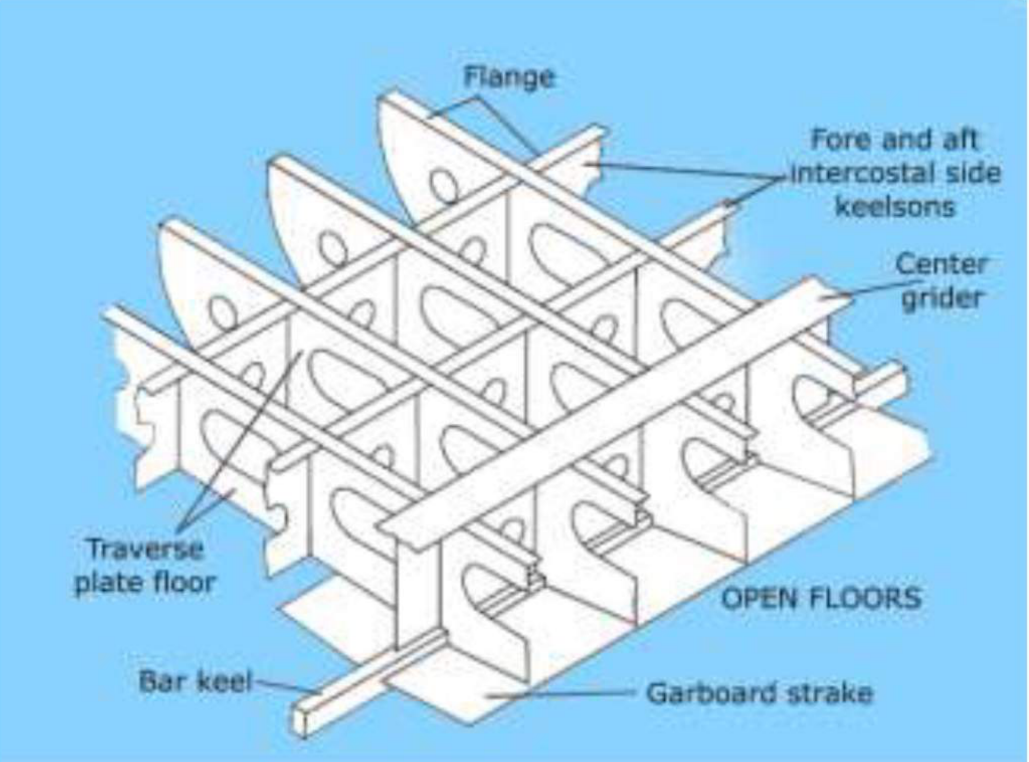
The flanged top and the thickened garboard strake are the same idea applied at two different places: add material where the member is working hardest rather than everywhere. The plate floor's top edge is its compression flange under the hydrostatic load; the garboard strake is the strake most likely to be damaged by grounding and most directly continuous with the keel.
6.2.3 Double bottom
All seagoing ships are double-bottomed. In such a structural arrangement, a tank top is provided above the plate and bracket floors.
Stated as the two watertight surfaces: in double bottom construction, the bottom of the ship has two complete layers of watertight hull surface — one outer layer forming the normal hull of the ship, and a second inner hull somewhat higher in the ship, which forms a redundant barrier to seawater in case the outer hull is damaged and leaks.
Bracket floors are a little different from plate floors, in as much as they are not comprised of one single plate running athwartship, but only brackets at the port and starboard ends, with struts that support the tank top with the bottom shell. Bracket floors are mostly placed at each frame, and plate floors are generally placed at every three to four frame spaces.
What the space is used for. The space within the double bottom — that is, between the tank top and the outer bottom shell — is used up for carrying ballast, fuel oil, dirty oil, fresh water, and other consumables. The oral's own list of why the double bottom tank is fitted:
- It is fitted to prevent foundering (flooding) in the event of hull damage.
- To control the stability by ballasting.
- To provide buoyancy.
- To store fresh water and fuel oil.
Fuel oil in the double bottom — the 2007 change. The space in between the two bottoms is often used as storage tanks for fresh water or ballast water. Fuel storage in the double bottom is not allowed for new-built ships since 2007, due to MARPOL 73/78. The reason is the same as the reason for the double bottom itself: a single-skin boundary between fuel and the sea is exactly the arrangement that produces the pollution the convention exists to prevent.
The double hull. An even more extensive protection is available as a double hull, where the second hull layer extends up the sides of the ship as well as in the bottom. The double bottom is therefore one case of a more general principle — keep the cargo away from the shell by an inner boundary — and the double hull is the same principle carried up the sides.
6.2.4 How the height of the double bottom is decided
One of the most important factors in designing a double bottom is deciding the height. It is governed by the height of the keel that is required by the ship: while estimating the scantlings, the designer first calculates, using the rules specified by the authorised classification society, the height of the centre girder, which must always be housed within the double bottom. Hence this factor decides the double bottom height.
The order of causation is worth stating, because it is the opposite of the intuitive one. The draught of the ship does not set the depth of the double bottom; the double bottom is deep enough to contain the centre girder the rules require, and the rest follows. A deeper double bottom then buys tank capacity and protection, and costs cargo space and stability.
6.2.5 Double bottom, transversely framed
With the members thus far defined, the transversely framed double bottom can be assembled. The arrangement is the one drawn in the tank top figures of §6.5: plate floors spanning transversely between the centre girder and the margin plate at intervals of three to four frame spaces, bracket floors at nearly every frame between them, intercostal side girders running fore and aft to break the span of the plate floors, a continuous centre girder on the centreline, a flat plate keel below it, and the tank top plating carried on all of them.
The stiffening members are therefore of two kinds working at right angles to each other, and this is the point of the arrangement:
- The transverse members (floors) carry the local water pressure on the shell into the tank top.
- The longitudinal members (girders, keel, tank top) carry the lengthwise bending of the hull girder, and stop the floors from being long enough to bend appreciably under the first load.
6.2.6 Double bottom, longitudinally framed
The difference from §6.2.5 is in what is doing the stiffening:
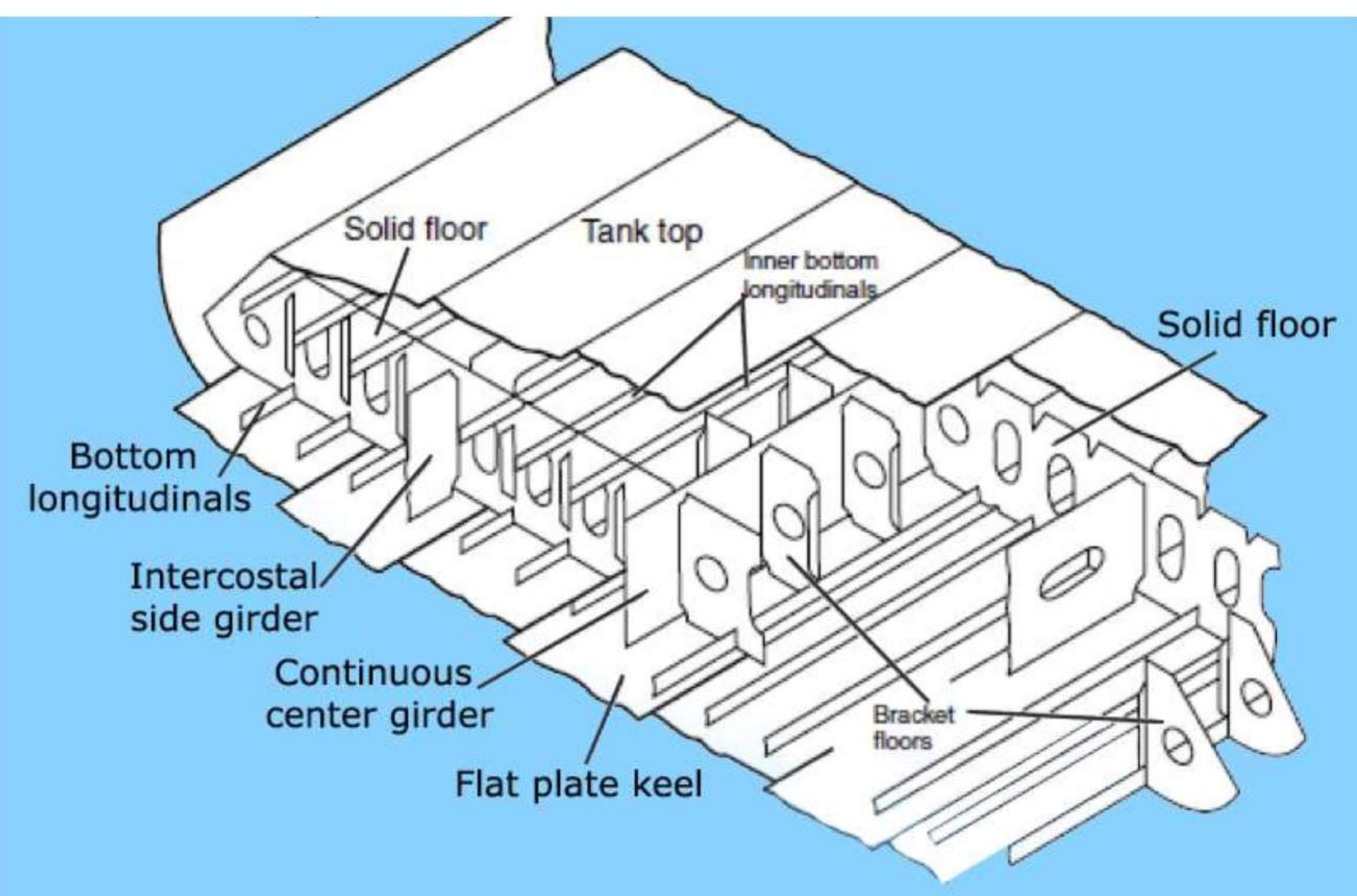
- The prime stiffening members are longitudinally running bulb sections or angle sections. The stiffeners on the bottom plating are called outer bottom longitudinals, and those that stiffen the tank top plating are called tank top longitudinals.
- The span of each longitudinal is equal to three or four frame spaces — that is, at each three or four frames there is a plate floor to support the longitudinal. A bracket floor is placed at almost every frame, but it does not support the longitudinals.
- Intercostal girders are used, as usual, to reduce the span of the plate floors.
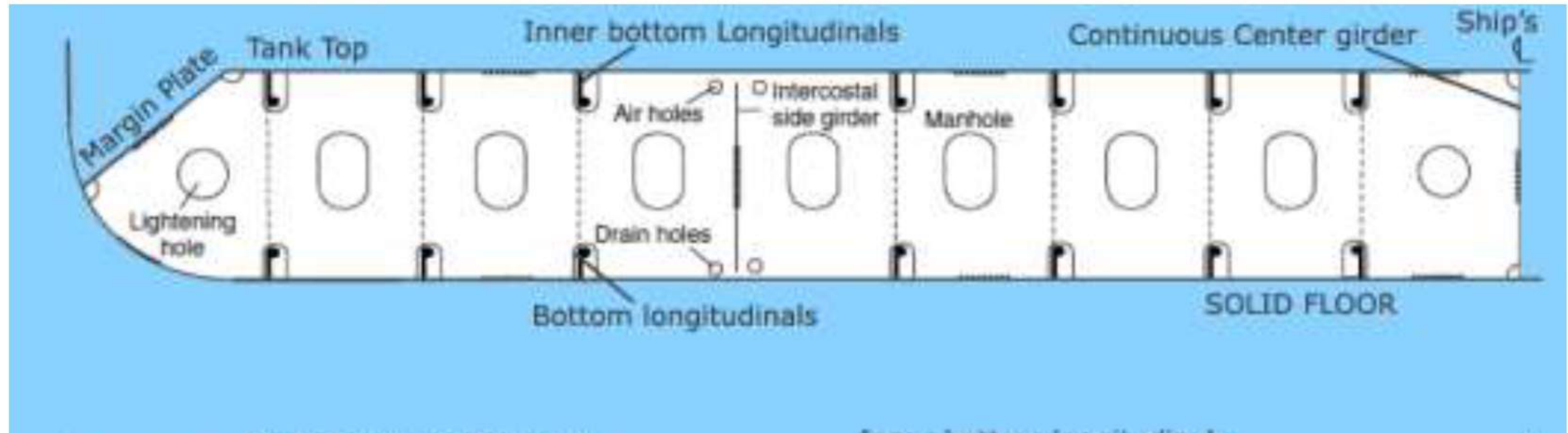
- The longitudinals run across the plate floors through holes called scallops. So in a frame where it is required to support the span of a longitudinal using a plate floor, the longitudinal is welded with a small plate to the plate floor, therefore rendering the scallop as a support end.
- In bracket floors, the tank top and bottom shell longitudinals are supported to each other by means of angle struts.
- In plate floors, the longitudinals of the tank top and bottom shell are supported to each other by flat bar stiffeners, to restrict bending, torsion and buckling.
- Drain holes are used for fluid drainage and air holes for the passage of air. Note their positions in the images, to visualise the exact layout.
- Margin plates are used in some designs, to lead the flow of waste fluids (bilge) towards the bilge wells on either side of the ship.
- A continuous centre girder runs through the length of the ship, supporting the entire bottom structure, the keel plate, and the garboard strake.
6.2.7 Analysing the bottom for every mode of failure
In modern analyses of the bottom structure, designers take a lot of care over various modes of failure. A disastrous mode of failure other than bending is buckling, to which a bottom structure can often be subjected.
The worked case: consider a ship to be hogging. The outer bottom shell undergoes a compression that leads to buckling of the bottom plate and associated structure. Torsion can also be a mode of failure, in the case of container ships.
The consequence, which is the reason the point is made at all:
If a designer certifies a bottom structure only on the basis of bending stress, without taking buckling or torsion into consideration, then when buckling occurs the structure might fail due to buckling — if its buckling strength is less than its bending strength — even when the bending stresses have not reached the failure limits.
Hence the principal design criteria must be decided based on all possible modes of failure, at various load cases, analysed by efficient and certified FEM tools, so as to attain a safe and economical factor of safety for the structure from all possibilities of failure at sea.
This is where Part 4 §4.2 finally bites on the bottom. The outer bottom shell is the bottom flange of the hull girder — in compression when hogging, in tension when sagging — and a thin plate in compression fails by buckling long before it fails by crushing. That is why the bottom structure is designed for a limit that has nothing to do with the bending stress the same member is carrying.
6.3 Floors
Floors are transverse vertical plates that run across the bottom of the ship from the centre girder to the bilge. Watertight or oil-tight floors are used to divide the double bottom space into suitable tanks.
The most direct answer to the "what is a floor" question is that it is a transverse bottom frame. Everything else in this section is a variant of it, and the variants are distinguished by what they are made of — which is exactly how they are defined:
6.3.1 The three types
| Type | Definition | Made of |
|---|---|---|
| Solid floor | The stiffener/floor plate is made of solid plate without any openings | One full plate, athwartships, unperforated |
| Plate floor | The stiffener/floor plate is made of solid plate with openings — done to optimise weight and to allow free flow of fluids, based on the purpose of the floor plate and the part of the ship | One full plate with lightening, drain, air and manhole openings |
| Bracket floor | The stiffener/floor plate is made of a built-up section with a large opening — also to optimise weight, and provided where much strength or structural integrity is not required, and according to the purpose of the area of the ship | Brackets at the ends with struts between, not one continuous plate |
The solid floor in detail. Solid floors are fitted to strengthen the bottom transversely and support the inner bottom. They run transversely from the continuous centre girder to the bilge, and manholes are provided; lightening holes are cut in each solid plate floor.
Note the small but real contradiction worth naming: the general definition says a solid floor has no openings, while the answer to that question says lightening holes are cut in each solid plate floor. The resolution is that "solid" means solid as opposed to built-up — one continuous plate running from centre girder to bilge — and it is the bracket floor that is not solid. The openings in a solid floor are the same weight-saving apertures as in a plate floor.
6.3.2 Where each type is fitted
Reading the assembly as a whole:
| Floor | Where fitted | Why there |
|---|---|---|
| Plate floor | At every frame spacing in a single bottom; in a double bottom at every three to four frame spaces | It is the primary transverse stiffener; it also supports the longitudinals in a longitudinally framed bottom |
| Bracket floor | At almost every frame in a double bottom; not used at all in the engine room region | Between the plate floors it supports the tank top with the bottom shell; where its strength is not needed it is a bracket and struts rather than a full plate |
| Solid floor | Wherever the bottom must be strengthened transversely and the inner bottom supported | The unperforated form, used where the openings would weaken it too far |
| Watertight or oil-tight floor | Dividing the double bottom into tanks | It is the tank boundary as well as a structural member |
In the engine room region, as §6.1.5 has it, all the frames are provided with plate floors and no bracket floors are used.
6.3.3 Watertight and oil-tight floors
Watertight or oil-tight floors are used to divide the double bottom space into suitable tanks. Their defining feature is therefore the same as any tank boundary: they must be continuous, welded to the shell, the tank top and the girders all round, with no openings of any kind. Every lightening hole, drain hole and air hole that a plate floor carries is precisely a hole through which liquid would pass if it were cut in a watertight floor.
6.4 Girders
6.4.1 Centre girder
A centre girder is a watertight longitudinal division which runs along the centreline from fore peak to aft peak bulkhead.
Its relation to the material around it:
- The keel runs along the centreline of the bottom plate, and for most ships it is of flat plate construction.
- The keel plate may be 1–2 m wide.
- The keel plate must be of full thickness for 3/5 L amidships, and may be gradually reduced towards the ends of the ship.
- The centre girder is connected to the keel plate and the inner bottom plating.
The 3/5 L rule is the same reasoning as the constant scantlings over the midship region in Part 4: the bending moment peaks over the middle of the ship, so the keel plate carries its full thickness there and is allowed to come down towards the ends where it is working less hard.
Its role in the bottom structure as built: a continuous centre girder runs through the length of the ship, supporting the entire bottom structure, the keel plate and the garboard strake. In the engine room, where the structure has to be extended further, the centre and side girders are extended forward a few floors to resist the distortion of the bottom due to slamming, and are discontinued as the width of the bottom gets narrow.
6.4.2 Side girders, or intercostals
Intercostals are plates, angles and so on, fitted down between others, or cut to allow other parts to pass through them. Side girders, parallel to the centre girder and fitted between the floors, are intercostals.
The rule by breadth:
| Breadth of vessel | Intercostal side girders required |
|---|---|
| Up to 20 metres | One on each side |
| Greater than 20 metres | Two such girders on each side |
Additional side girders are provided in the engine room, and also in the pounding region.
Why the number grows with breadth. This is the rule from §6.2.1 stated as a table: the plate floor is a beam spanning from the centre girder to the margin plate, and the bending moment in a beam increases with span. A wider ship means a longer floor, so it must be broken into more spans; the number of intercostals is the span control.
The name matters. "Intercostal" is not a synonym for "side girder" — it describes the construction: fitted between the floors, in pieces, rather than run continuously through them. It is the opposite of the continuous centre girder, and the distinction is what the two names are for.
6.4.3 Girders as continuous fore-and-aft stiffening under the deck
A girder is a continuous stiffening member which runs fore and aft in a ship to support the deck. The same member appears in the bottom structure, where the double bottom girder is a longitudinal, vertical plate extending from the bottom shell to the inner bottom, usually with large holes for access and weight saving, and taking either the continuous centre girder or intercostal side girder form.
The point of holding the two together is that "girder" is a function, not a position: it is continuous fore-and-aft stiffening, and whether it is under the deck, on the centreline of the bottom or between the floors is a matter of which surface it is stiffening.
6.4.4 The girders of a ship, taken as a set
The three girders of a ship, and how they differ:
| Girder | Definition |
|---|---|
| Deck girder | A continuous stiffening member which runs fore and aft along a ship to support the deck |
| Double bottom girder | A longitudinal, vertical plate extending from the bottom shell to the inner bottom, usually with large holes for access and weight saving — continuous centre girder, intercostal side girder |
| Hull girder | The components of a hull structure that contribute to its strength when subjected to longitudinal and/or transverse bending — e.g. the shell plating, decks, inner bottom, longitudinals, bulkheads and girders |
The third is the one to be careful with, because it is the only one of the three that is not a member. The hull girder is the working section made up of all the others, as Part 4 §4.4.1 has it, and the deck girder and the double bottom girder are among its parts.
6.5 Boundaries and the tank top
6.5.1 Margin plate
At the bilges, the tank top may be either continued straight out to the shell by means of a tank margin plate, which is watertight and sets an angle of about 45° to the tank top, meeting the shell almost at right angles.
Defined from the other direction: the margin plate is the outboard strake of the inner bottom. When the margin plate is turned down at the bilge it forms the outboard boundary of the double bottom, connecting the inner bottom to the shell plating at the bilge.
The 45° is not an arbitrary angle. It is the angle at which the plate can transfer the load from the tank top into the shell without either being bent sharply or being laid so flat that it stops being an efficient tie — and it is the arrangement that closes the outboard end of the double bottom watertightly while letting the shell take up its own bilge curvature.
6.5.2 Tank top continued straight out to the shell
The alternative to the margin plate is named in the same sentence: the tank top may be either continued straight out to the shell by means of a tank margin plate, or the tank top may be continued straight out to the shell directly.
The two arrangements differ in where the double bottom ends. With a margin plate the double bottom's outboard boundary is the plate itself, at 45°, meeting the shell almost at right angles; with the tank top carried straight out the inner bottom runs out to meet the shell, and the double bottom is closed by the shell itself. The first gives a narrower double bottom and a bilge pocket; the second a wider one.
6.5.3 Inner bottom
The tank top is the inner bottom — the plating that forms the upper boundary of the double bottom space, on which the cargo, or the hold, sits.
It is the member doing the largest part of the work in this part of the ship, and it is the reason the double bottom is a structural improvement rather than only a double skin:
- It is the upper flange of the double bottom girder, so it adds to the section modulus of the hull girder along the middle of the ship (Part 4 §4.4.1).
- It takes the cargo weight and spreads it onto the floors and girders below.
- It is the boundary between the cargo and the tanks.
6.5.4 Rising tanks
Rising tanks are double bottom spaces in which the inner bottom is higher at the centreline than at the sides. This arrangement has the advantage of allowing moisture from the cargo to drain into the bilge pockets on each side.
The geometry is worth connecting to §6.5.1: a rising tank slopes the inner bottom down towards the bilge, which is exactly where the margin plate has already created a bilge well on each side. The two arrangements are designed to work together — the rising tank collects the moisture at the sides, and the margin plate's outboard pocket is where it can be pumped from.
6.5.5 Deep tank
Deep tanks are tanks extending from the bottom or inner bottom up to, or higher than, the lowest deck. They are often fitted with hatches so that they may also be used for dry cargo in lieu of fuel oil, ballast water or liquid cargo.
The construction requirements:
- Location: Forward of the machinery space, to provide sufficient ballast capacity.
- Fitted with hatches, so they may also be used for dry cargo or vegetable oil as cargo; hatches prevent water from entering.
- A wash plate must be fitted at the centreline to reduce the free surface effect.
- Bulkhead stiffeners must be spaced not more than 600 mm apart, and must be bracketed at the head and foot.
- The deck plating which forms the tank top must be at least 1 mm thicker than that boundary of the bulkhead.
- The tank structure is designed to a head of water up to the top of the overflow pipe, and the tank is tested to this head, or to a height of 2.45 m above the top of the tank, whichever is higher.
Function:
- Used to carry a certain amount of water ballast.
- Used to carry dry cargo normally, but water ballast when the ship is light.
- Used to carry oil cargo, provided that its flash point is not less than 60°C.
- Location and construction: a tank extending from the bottom or inner bottom up to higher than the lowest deck.
The wash plate at the centreline is the free-surface remedy of Part 3 §3.4 applied to a full-depth tank: an unbroken liquid surface a whole deck deep would be a serious loss of stability, and the wash plate breaks it without preventing the tank from being used.
6.5.6 Deep tank used for dry cargo in lieu of liquid
The dual use is the defining feature of the deep tank rather than a bonus. Because it is fitted with hatches, it can be filled with dry cargo — and with vegetable oil, which is neither a dry cargo in the ordinary sense nor a fuel oil — and then ballasted when the ship is light.
What makes the dual use possible is the set of features in §6.5.5 that would otherwise look over-specified for a ballast tank: the hatches that keep water out and let cargo in, the closely spaced bracketed stiffeners that resist a head of cargo as well as a head of water, and the thicker tank top plating that takes the impact and grab-bucket damage that dry cargo loading and discharge produce.
6.6 Openings and access
6.6.1 Limber holes
A limber hole is a small hole cut in a plate near the bottom of the frame or other structural member to permit the passage of water or oil.
The definition is worth reading carefully, because it fixes where the hole goes — near the bottom of the member — and that is the whole of its function. The hole is placed so that it is at the lowest point of the space it serves, so that nothing can pool behind the frame. A limber hole cut at the top of a member would be a lightening hole, not a limber hole.
6.6.2 Lightening holes
Lightening holes are large apertures cut in floor plates, side girders and tank bracket plates. In double bottom vessels they provide access to the different cells for inspection and upkeep, besides taking weight off the structure, which is their principal object. In a general sense, any hole cut to reduce weight without impairing strength.
The definition contains a hierarchy worth stating plainly, because it is easy to answer backwards:
| Hole | Principal object |
|---|---|
| Lightening hole | Taking weight off the structure — access is the secondary benefit |
| Drain hole | Drainage of liquids |
| Air hole | Passage of air |
| Manhole | Access for a person, flanged |
| Limber hole | Passage of water or oil at the bottom of a member |
The drain holes are provided on the plate floors to help drainage of liquids, and air holes are used for the passage of air — their positions in the drawings are what show the exact layout of a bottom structure.
6.6.3 Manhole access to the double bottom cells
Lightening holes provide access to the different cells for inspection and upkeep, and the access itself is by flanged manholes. In the drawings of the double bottom the manhole is shown as a separate, smaller, flanged opening in the plate floor, distinct from the larger unflanged lightening aperture.
The distinction is the reason both exist in the same member. A lightening hole is cut for weight and is not shaped for a person to pass or for a cover to seal; a flanged manhole is cut and stiffened precisely so that a cover can be bolted on it and the tank kept watertight. Every double bottom cell must be enterable for the thickness gauging and tank inspection that follow a survey.
6.7 Keels
6.7.1 The types of keel, taken as a set
The types of keel are: bar keel, duct keel, and flat plate keel.
There are three, and one of them is the standard for every seagoing vessel of any size:
| Keel | Used on |
|---|---|
| Flat plate keel | All types of sea-going vessels |
| Bar keel | Ferries or boats that are to be grounding |
| Duct keel | Some double bottoms, where pipework must run through the bottom |
6.7.2 Flat plate keel
- Used in all types of sea-going vessels.
- "Flat keel" basically means a single bottom in the old sense of the term — in the old days a wooden plank was placed above the floors to facilitate cargo carriage, but that does not make it a double bottom, because if it is a double bottom it must be watertight.
- The keel plate may be 1–2 m wide.
- It must be of full thickness for 3/5 L amidships, and may be gradually reduced towards the ends of the ship.
- The centre girder is connected to the keel plate and the inner bottom plating.
The keel runs along the centreline of the bottom plate, and for most ships it is of flat plate construction. It is also the member the rest of the bottom is built up from: the garboard strake is the shell strake next to it, the centre girder stands on it, and in a single-bottom ship the floors are flanged where they meet it.
Two plates connect the keel to the ends of the ship, and both are worth knowing by name because they come up in the oral with the keel:
- Coffin plates are used to connect the stern frame to the flat plate keel. The stern frame is extended forward far enough — two or three frame spaces — to provide a good connection with the flat plate keel, and the aft-most plate of the keel, the coffin plate, is dished around the extension.
- Shoe plates are used to connect the stem to the flat plate keel. The forward end of the shoe plate is dished around the stem, whilst the after end is flattened to connect with the keel plate.
The pair is easy to keep straight by the end of the ship each belongs to: the shoe is forward and connects to the stem; the coffin is aft and connects to the stern frame.
6.7.3 Bar keel
- A bar is placed in the centre of the keel, called a bar keel.
- These consist of one or more solid bars, which are supported by frames running around the vessel.
- The either side of the hull attached to the bar keel is called the garboard strake.
- These types of keels are incorporated in ferries or boats that are to be grounding.
- Keelson plate: a longitudinal beam on top of the keel of a vessel, for strength and stiffness.
In the single-bottom ship of §6.2.2 the bar is slightly protruded outside the outer bottom shell, and the garboard strake just adjacent to it is thicker than the remaining bottom shell. That protruding bar is the whole point: it is the member that takes the grounding, and it is sacrificial in the same sense that a bilge keel is — better a bar worn away than a shell plate torn open.
6.7.4 Duct keel
- Some double bottoms have a duct keel fitted along the centreline.
- It is an internal watertight passage running along the length of the ship, usually from the collision bulkhead or forepeak to the forward machinery space bulkhead.
- It is also called a box keel, and allows pipes and other services throughout the keel length.
Construction:
| Item | Specification |
|---|---|
| Girders | Two longitudinal girders, spaced not more than 2.0 m apart (KS3 gives 1.83 m) — this ensures the girders rest on the docking blocks |
| Scantlings | Keel plate and tank top above the duct keel must have increased scantlings, to compensate for the reduced strength of the transverse floors |
| Stiffeners | Fitted to the shell and bottom plating at alternate frame spaces, and bracketed to the longitudinal girders |
| Access | Usually by a watertight manhole at the forward end of the machinery space |
| Extent | Fitted from forward of the engine room bulkhead to aft of the collision bulkhead; aft of that we cannot require a duct keel because the pipe passes through to the shaft tunnel |
| Not required | Not required in the machinery space or further aft — pipework runs along the top of the engine room double bottom and along the shaft tunnel |
An internal passage of watertight construction — two longitudinal girders spaced not more than 2.0 m apart — running some distance along the length of the ship, often from the forepeak to the forward machinery space bulkhead, to carry the pipe work, with an entrance at the forward machinery space via a watertight manhole.
Why 2.0 m or 1.83 m, and not simply "narrow enough". The spacing is set by the docking blocks. The keel rests on the blocks when the ship is in dry dock, and if the two girders forming the duct are further apart than the block spacing, the bottom between them is unsupported and is carried by the duct itself. Setting the girders to the block spacing turns the duct into part of the docking arrangement instead of a weak panel.
What the duct is for:
- Used to carry pipework along the length of the ship to various holds and tanks.
- Prevents any contamination which could occur if a pipe ruptured with cargo.
- Facilitates pipes passing through the cargo holds, thus isolating piping from cargo contact.
- Enables lines to pass through that facilitate draining.
The reason a ship has a duct keel is therefore a segregation requirement dressed as a structural one: the pipes must run from the pump room to the cargo tanks, and running them through the cargo tanks themselves would mean a leak put cargo into cargo. The duct gives them a watertight corridor that no cargo occupies.
6.7.5 Bilge keel — purpose
Purpose:
- To damp the rolling motion of the vessel.
- Protection of the bilge on grounding.
- Increase the longitudinal strength.
Defined as a structure: it is a longitudinal structure which runs along the length of the lower side of the ship's hull to reduce rolling motion — or, as the fitting answer has it, the longitudinal structure that runs along much of the length down to the lower side of the ship's hull to reduce the rolling motion of the ship.
The first purpose is the one that matters and the one the mechanism explains. A bilge keel works by setting up a resistance to the water as the ship rolls, which is why its depth has to be adequate — see the two factors below — and why it can be of almost any plate thickness, since it is carrying no structural load at all in the ordinary sense.
6.7.6 Bilge keel — location and connection
Length and position:
- Bilge keels are about one half of the length of the ship.
- They run over the midship portion of the hull, extending forward and aft of amidships.
- These projections are arranged at the bilge to lie above the line of the bottom shell and within the breadth of the ship, thus being partially protected against damage.
- The keel is tapered gradually at the ends to prevent stress concentration, which can cause the bilge plating to crack.
Depth, and the two factors that decide it:
- The web must be deep enough to penetrate the boundary layer of water travelling with the ship.
- If the web is too deep, the force of water when rolling may cause damage.
Bilge keels of 250 mm to 400 mm in depth are fitted to ocean-going ships.
Connection:
- The bilge keel is not directly welded to the bilge plate. Instead, a ground bar is attached to the bilge plate, and the connection of the ground bar to the shell is by continuous fillet welds.
- The ground bar thickness is at least that of the bilge plate, or 14 mm, whichever is less.
- The material is the same as the bilge plating.
- Bilge keels are connected to the hull by a riveted angle or T-bar, which is strongly attached to the shell plating but less strongly connected to the bulb plate. If the bilge keel is ripped off, it will then part at the outer joint, leaving the hull intact.
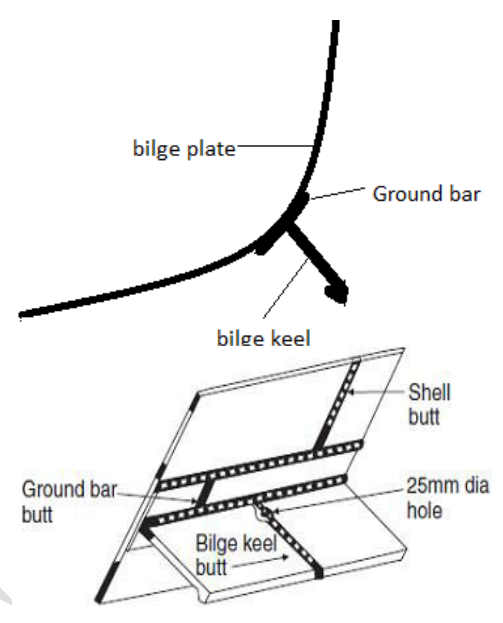
The deliberate weakness is the design, and it is the same idea as the shear pin: a bilge keel is within the breadth of the ship and above the line of the bottom shell so that a moderate grounding slides it off rather than opening the shell. The ground bar is what makes that possible, because the continuous fillet weld to the shell is made on the bar rather than on the keel, and the bar's thickness — the same as the bilge plate, or 14 mm, whichever is less — is chosen so that the shell is never the thinnest part of the joint.
6.8 Summary — what each member of the bottom is doing
| Member | Direction | Job |
|---|---|---|
| Longitudinals (outer bottom, tank top) | Fore and aft | Prime stiffening in a longitudinally framed bottom; add to the hull girder's section modulus |
| Plate floor | Athwartships | Transverse stiffener; supports the longitudinals; carries water pressure from shell to tank top |
| Bracket floor | Athwartships | The light form of the floor, between the plate floors, where full strength is not needed |
| Centre girder | Fore and aft, centreline | Supports the entire bottom structure, the keel plate and the garboard strake |
| Intercostal side girder | Fore and aft | Breaks the span of the plate floors; one per side up to 20 m breadth, two per side above |
| Tank top / inner bottom | Fore and aft | Upper flange of the double bottom, cargo platform, tank boundary |
| Margin plate | 45° at the bilge | Watertight outboard boundary of the double bottom |
| Keel plate | Fore and aft, centreline | The bottom flange of the girder, full thickness for 3/5 L amidships |
| Keel (bar / duct) | Fore and aft, centreline | Grounding protection, or a watertight pipe corridor |
| Bilge keel | Fore and aft, at the bilge | Damping of roll; sacrificial on grounding |
| Limber, drain, air holes | Through the members | Fluid and air movement, at the lowest and highest points respectively |
| Lightening holes, manholes | Through the members | Weight saving, chiefly; access secondarily |