
Ship Hydrostatics: Buoyancy, Displacement and Trim
Why the ship floats and how much water she accounts for — Archimedes, the displacement triangle, tonnes per centimetre and the trim she takes when a weight moves.
Key Principles at a Glance 8 points
- Every floating body displaces its own weight of the liquid it floats in; buoyancy acts vertically upwards through the centre of buoyancy, which is the centroid of the underwater volume.
- Displacement is the weight of water the ship displaces, and it equals the total weight of the ship, its cargo, fuel, stores and water.
- Displacement is the sum of lightweight and deadweight. Deadweight is the carrying capacity — cargo, fuel, water, stores and crew — and is quoted for the summer load draught.
- Reserve buoyancy is the watertight volume above the waterline, and it is spent by adding weight just as surely as by holing the hull.
- Permeability is the fraction of a compartment that water can actually occupy, so a machinery space is far more permeable than a cargo hold full of cargo.
- Tonnes per centimetre immersion is the mass that changes the mean draught by one centimetre, and it is not constant — it grows with draught as the waterplane area grows.
- Moving from salt water to fresh water increases draught, and the fresh water allowance is the allowance built into the load line marks for exactly that change.
- A weight loaded at the longitudinal centre of flotation changes draught only and not trim; loaded away from it, the ship trims about the LCF.
2.1 Buoyancy and displacement
Why the ship floats, and how much water she accounts for.
2.1.1 Archimedes' principle
If a solid body is immersed in a liquid there is an apparent loss in weight. This loss in weight is the upthrust exerted by the liquid on the body, and it is equal to the weight of the volume of liquid which the body displaces.
The reasoning behind it is worth holding on to, because it is what makes buoyancy a force rather than a coincidence: when a substance is immersed in water it appears to suffer a loss in weight. Since the actual mass of the substance has not changed, there must be a force acting vertically upwards to create that apparent loss. This force is called the force of buoyancy, and it is considered to act vertically upwards through a point called the centre of buoyancy.
In its floating-body form, which is the version actually used on board: every floating body displaces its own weight of the liquid in which it floats. For a vessel to float freely in water, the weight of the vessel must be equal to the weight of the volume of water it displaces.
2.1.2 Buoyancy
Buoyancy is the upthrust exerted by the water on the ship. If the ship floats freely, the buoyancy is equal to the weight of the ship. It acts vertically upwards through the centre of buoyancy.
2.1.3 Centre of buoyancy
The centre of buoyancy is the point through which the total force of buoyancy is considered to act. Its position moves as the underwater shape changes — with draught, with trim and with heel. The whole of Part 3 turns on that movement.
2.1.4 Centre of gravity
The centre of gravity of an object is the point at which the whole weight of the object may be regarded as acting. If the object is suspended from this point, then it will remain balanced and will not tilt.
Centre of gravity is fixed by the distribution of mass on board; the centre of buoyancy is not, because it follows the shape of the underwater volume. The contrast shows up cleanly in the difference between heel and list:
| Cause | Centre of gravity | Centre of buoyancy | GM | |
|---|---|---|---|---|
| Heel | External — wave, swell, current, wind | Does not change; stays on the centreline | Shifts | Remains positive |
| List | Internal — uneven loading, discharging, shifting, ballasting, bunkering | Changes; moves off the centreline | Shifts | Remains positive |
That asymmetry between the two points is the whole basis of stability.
2.1.5 Displacement
Displacement is the mass of the volume of water displaced by the ship. When a ship is floating freely at rest, the mass of the ship is equal to the mass of the volume of water displaced by the ship, and this mass is therefore known as the displacement of the ship. A ship floating freely displaces a mass of water equal to its own mass. It is the weight of the water that a ship pushes aside when she is floating.
2.1.6 Light displacement, or light ship weight
The displacement of the ship complete and ready for sea, but with nothing consumable or movable on board. The definition that matters is the one that specifies what is left in:
Light displacement is the displacement of the ship complete & ready for sea but no crew, passengers, baggage, stores, fuel, water, cargo on board. Boilers, if any, are filled with water to working level.
Note that last sentence — boiler water at working level is part of light displacement. It is the item most often got wrong.
In SOLAS wording, lightweight is the displacement of the ship in tonnes without cargo, fuel oil, lube oil, ballast water, fresh water, stores, crew and effects. It is the mass of the ship with all of its structures, including all steels, decks, cargo gear and machinery. A short form: the actual weight of a vessel when complete and ready for service but empty.
The exclusion list, consolidated: crew, passengers, baggage, stores, fuel oil, lube oil, fresh water, ballast water, cargo, effects. Included: hull and all structure, machinery, cargo gear, and boiler water to working level.
2.1.7 Load displacement
Load displacement is at the maximum permissible draught and is made up of the light displacement and the dead weight.
2.1.8 Deadweight
Deadweight is the weight of cargo, fuel, water, stores and so on that a ship can carry — the actual amount of weight in tonnes a vessel can carry when loaded to the maximum permissible draught, including fuel, fresh water, gear supplies, catch and crew.
The SOLAS definition, which is the one to give if asked formally:
Deadweight is the difference in tonnes between the displacement of a ship in water of a specific gravity of 1.025 at the load waterline corresponding to the assigned summer freeboard and the lightweight of the ship.
Deadweight is the sum of all weights including fuel oil, lube oil, cargo, ballast water, fresh water, stores, crew and effects. It does not include the weight of the ship or the machinery.
2.1.9 Deadweight, lightweight, displacement, GRT and NRT taken together
The one identity that ties the weight terms together:
The two tonnage terms are not part of that identity — they are volumes, not weights:
Net tonnage = Earning space
Tonnes is related to weight, whereas tonnage is related to volume. That distinction is the single most common place where the oral answer goes wrong.
Worked through on a real ship, the five figures sit like this:
| Quantity | Value |
|---|---|
| Gross tonnage | 29 708 |
| Summer deadweight | 49 990 tonnes |
| Length overall × breadth extreme | 183.31 × 32.2 m |
2.1.10 Reserve buoyancy
Reserve buoyancy is the watertight volume of the ship above the waterline. It is the buoyancy a ship can call upon to meet losses of buoyancy due to damage of the main hull, and its use in the general working of the ship is to provide a sufficiency of freeboard to make the vessel seaworthy.
It is the potential buoyancy of a ship, and it depends on the intact watertight volume above the waterline. If mass is added to the ship, or if buoyancy is lost through bilging, the reserve buoyancy is converted into buoyancy by increasing draught.
Two consequences worth holding on to:
- Reserve buoyancy is spent by adding weight just as surely as by holing the hull. The ship answers both by going deeper. That is why an overloaded ship is a damaged ship in slow motion.
- Freeboard is the visible measure of it. The greater the freeboard, the larger the above-water volume, and the more reserve buoyancy available to keep the ship afloat in the event of damage.
Freeboard exists to deliver reserve buoyancy. Its three stated purposes are to ensure the ship cannot be loaded beyond her strength, to provide adequate reserve buoyancy, and to keep the deck high enough from the water to enable the crew to navigate and handle her in all weather. It is also a condition of assignment: enough reserve buoyancy must be possessed before a freeboard is assigned at all.
2.1.11 Permeability
Permeability (µ) is the proportion of a compartment's volume that will actually fill with water if the compartment is flooded — the ratio of the volume within the space assumed to be occupied by water to the total volume of that compartment. Equivalently, the ratio of water which can enter to the volume of the empty compartment.
Accepted values:
| Space | µ |
|---|---|
| Machinery space | 85 % |
| Accommodation | 95 % |
| Cargo hold (average) | 60 % |
Permeability of a space is the percentage of empty volume in that space, and it is used in ship survivability and damaged stability calculations. It is a percentage from 0 to 100, or alternatively a coefficient from 0 to 1. It is the percentage of the volume of the space which may be occupied by seawater if the space is flooded, the remaining volume being occupied by machinery, cargo, accommodation spaces and so on.
The number that surprises people is the tank figure. Permeability for an oil-filled tank is only about 5 %, against 60–65 % for a grain cargo hold. Far less water enters a bilged tanker compartment, and that is one of the reasons an oil tanker can be assigned less freeboard than a bulk carrier of the same size.
2.1.12 Wetted surface area, and Simpson's rule
The wetted surface area of a ship is the area of the hull in contact with the water. It may be found by putting the transverse girths of the ship, from waterline to waterline, through Simpson's Rule and adding an allowance for the longitudinal curvature of the shell. To this area should be added the wetted surface area of appendages such as cruiser stern, rudder and bilge keels.
The appendage allowance is not optional. Cruiser stern, rudder and bilge keels are wetted surfaces and they add to frictional resistance.
Two related uses:
- Wetted surface area is the S term in the Froude number, so an increase in length — and therefore in wetted surface — increases the Froude number.
- The shell expansion plan can be used to find painting areas — topside, boot topping and bottom — by applying Simpson's rules directly. The vertical scale on a shell expansion differs from the horizontal scale, so an adjustment has to be made when calculating areas from it.
2.1.13 Denny's equation
where S is the wetted surface area, L the length, d the draught and ∇ the volume of displacement.
The second term is the allowance for the fineness of the ends. As the hull gets finer for its length and draught, the displacement volume falls and the wetted surface falls with it.
2.1.14 Taylor's equation
where Δ is the displacement and c is a coefficient depending on the ship type and on the units used.
2.2 Waterplane, immersion and trim
2.2.1 Tonnes per centimetre immersion
The tonne per centimetre immersion (TPC) of a ship at any given draught is the mass required to increase the mean draught by one centimetre. More fully: it is the mass which must be loaded or discharged to change a ship's mean draft in salt water by one centimetre. It varies with the draught and with the water density, and because changes in draught cause a change in displacement, TPC is what is used to calculate that change.
where Aw is the waterplane area and ρ the density of the water.
Three results follow from the formula:
- TPC of a ship floating in water of uniform density depends solely on the area of waterplane.
- The parallel sinkage resulting from a particular loading in fresh water would be more than if the same loading were done in sea water.
- The crew must recalculate the predicted new drafts after loading or unloading when the ship moves from fresh water to sea water or vice versa, to avoid unexpected observations.
2.2.2 TPC against draught
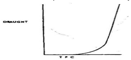
TPC rises with draught, because waterplane area rises with draught for a normal ship-shaped hull. The curve is the reason a ship becomes progressively harder to put down as she loads.
The property of the curve that gets asked about:
The area between the TPC curve and the draught axis to any given draught represents the displacement of the ship at that draught, while its centroid represents the vertical position of the centre of buoyancy.
2.2.3 TPC in fresh water against sea water
TPC is directly proportional to density, so TPC in sea water is greater than TPC in fresh water. The same weight therefore puts the ship further down in fresh water than it would in salt, which is the physical origin of the fresh water allowance.
2.2.4 Fresh water allowance
Fresh water allowance (FWA) is the rise or change in draft caused when a ship passes from salt water to fresh water. The chain of reasoning:
- When the vessel moves from salt water to fresh water, the difference in density makes the vessel sink more, so that the summer load line submerges below the waterline.
- This additional sinkage is just enough to achieve more underwater volume, so that the vessel gets exactly the same buoyancy as she had floating in sea water.
- This rise or change in draft is called the fresh water allowance.
Summer draft + FWA = Freshwater draft
Consequences:
- If a vessel is loading in fresh water, she can load up to the fresh water draft.
- When the vessel travels from fresh water to sea water, she will rise, and her draft at salt water will be the summer draft.
Geometrically, FWA is a distance on the load line mark: F is the summer fresh water load line, and the distance between the S mark and the F mark is the fresh water allowance.
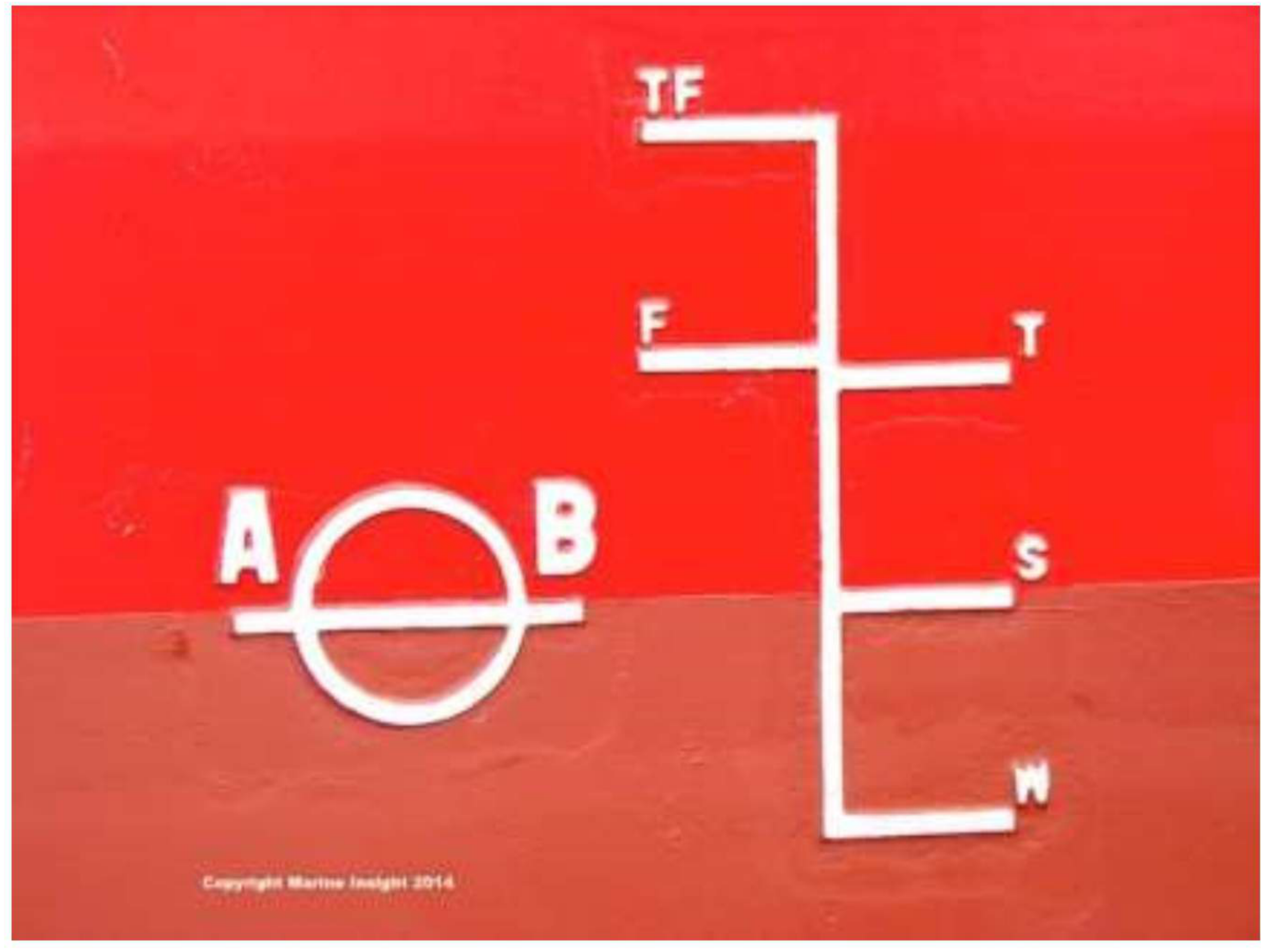
The two densities the marks are built on: fresh water is taken as 1000 kg/m³ and sea water as 1025 kg/m³. A ship loaded to her fresh water mark in fresh water will float at her summer mark once she has passed into sea water, and one loaded to her tropical fresh water mark will float at her tropical mark.
2.2.5 Longitudinal centre of flotation
The longitudinal centre of flotation (LCF) is the point about which the ship will trim when weights are loaded or discharged. If the weight is added at the LCF point, trim will not change — only the draft changes.
That single sentence is the practical answer to "where do I put it so the ship doesn't trim", and it is why the LCF is tabulated against draught in the trim and stability booklet.
2.2.6 Trim
Trim changes when the centre of buoyancy moves longitudinally:
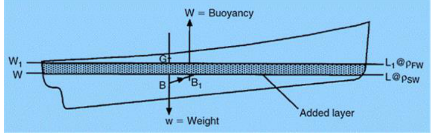
When a ship passes from water of one density to water of another density the mean draft is changed and if the ship is heavily trimmed, the change in the position of the centre of buoyancy will cause the trim to change. When the vessel was in SW, waterline was WL, centre of gravity and centre of buoyancy was in the same line. Once the vessel moves to FW, water line becomes W1L1. As the extra volume of water has been displaced, centre of buoyancy has shifted to B1. As now G and B are not in the centreline, it gives a trimming moment which will be equal to the product of the displacement and the longitudinal distance between centre of gravity and centre of buoyancy. The ship will trim more to bring G and B back in the same vertical line.
The sign convention: when trim is by the stern, trim is positive, hence the centre of flotation will also be aft, and vice versa.
2.2.7 A ship passing from salt water into fresh water
Four quantities change at once and candidates routinely get the direction of one of them wrong. Taken as a whole:
Effect on draft and TPC. As the ship moves from SW to FW, the reduction in density makes her sink more. The additional sinkage is just enough to achieve more underwater volume so that the vessel gets exactly the buoyancy she had in sea water. TPC is directly proportional to density, so when density falls, TPC falls, which results in additional sinkage — hence draft increases.
Effect on trim and LCF. The mean draft changes, and because the centre of buoyancy shifts longitudinally, a trimming moment is set up equal to the product of the displacement and the longitudinal distance between G and B. The ship trims until G and B are back in the same vertical line. If the resulting trim is by the stern, the trim is positive and the centre of flotation moves aft; if by the head, the reverse.
Effect on list. None. "There will be no effect on the list of the vessel." The change of density is symmetrical about the centreline, so there is no transverse moment.
2.2.8 Bonjean curves
Bonjean curves are curves of areas and moments of sections versus draught, plotted on the sheer plan. They are used to determine the force of buoyancy during launching.
The application is broader than launching. Bonjean curves give the sectional area at any station at any draught, which is how you find the displacement and the position of the centre of buoyancy of a ship trimmed or heeled to an attitude no hydrostatic table covers.
2.3 Tonnage measurement
2.3.1 Gross tonnage
Gross tonnage is a measure of a ship's overall internal enclosed volume. It applies to the vessel, not to the cargo, and has nothing to do with weight. In words: gross tonnage equals earning space plus non-earning space, measured over the ship's overall internal enclosed volume from keel to funnel including cargo space.
The spaces it is built from:
- The under-deck tonnage, plus
- Any tween deck space between the second and upper decks.
- Any enclosed spaces above the upper deck.
- Any excess of hatchways over 0.5 % of the gross tonnage.
- At the ship owner's option and with the surveyor's approval, any engine light and air space on or above the upper deck.
The older arithmetic and the two variables the modern formula uses: gross tonnage is determined by dividing by 100 the contents, in cubic feet, of the vessel's enclosed spaces, and is based on V, the ship's total volume in cubic metres, and K, a multiplier based on the ship volume.
2.3.2 Net register tonnage
Net tonnage is the volume of the ship available for cargo and passengers after the spaces needed to run the ship have been deducted. It is the total volume of the ship's cargo spaces — earning spaces only. Stated at length, it is gross tonnage minus the space occupied by accommodation for crew, by machinery, for navigation, by the engine room and by fuel, so that net tonnage represents the available space for accommodation of passengers and stowage of cargo.
The full deduction list, which is the version to memorise because the individual items are asked:
| Space deducted from gross tonnage | |
|---|---|
| (a) | Master's accommodation |
| (b) | Crew accommodation and an allowance for provision stores |
| (c) | Wheelhouse, chartroom, radio room and navigation aids room |
| (d) | Chain locker, steering gear space, anchor gear and capstan space |
| (e) | Space for safety equipment and batteries |
| (f) | Workshops and storerooms for pumpmen, electrician, carpenter, boatswain and the lamp room |
| (g) | Donkey engine and donkey boiler space, if outside the engine room |
| (h) | Pump room, if outside the engine room |
| (i) | In sailing ships, the storage space required for the sails, with an upper limit of 24 % of the gross tonnage |
| (j) | Water ballast spaces if used only for that purpose. The total deduction for water ballast, including double bottom spaces, may not exceed 19 % of the gross tonnage |
2.3.3 How gross and net tonnage are actually calculated
The convention and its dates:
- The International Convention on Tonnage Measurement of Ships 1969 was prepared at a conference convened by IMO in 1969 with the intention of producing a universally acceptable system of tonnage measurement.
- The convention came into force on 8 July 1982.
- All ships constructed on or after that date were measured for tonnage in accordance with the 1969 Convention.
- Ships built before that date were permitted, if the owner so desired, to retain their existing tonnages for a period of 12 years from that date — so all ships were required to be measured under the 1969 Convention by 18 July 1994.
Gross tonnage
K1 = 0.2 + 0.02 log10 V
- V = total volume of all enclosed spaces in cubic metres
Net tonnage
NT = K2 × Vc × (4d / 3D)2 + K3 × (N1 + N2 / 10)
NT = K2 × Vc × (4d / 3D)2
| Symbol | Meaning |
|---|---|
Vc | Total volume of cargo spaces in cubic metres |
d | Moulded draft amidships in metres (summer load line draft, or deepest subdivision load line in the case of passenger ships) |
D | Moulded depth in metres amidships |
K2 | 0.2 + 0.02 log10 Vc |
K3 | 1.25 (GT + 10 000) / 10 000 |
N1 | Number of passengers in cabins with not more than 8 berths |
N2 | Number of other passengers |
N1 + N2 is the total number of passengers the ship is permitted to carry.
The limits on the result:
- The term
K2 Vcis not to be taken as less than0.25 GT. NTis not to be taken as less than0.30 GT.
And the practical reading of the d/D term: vessels with high freeboards — that is, low draft-to-depth ratios — will have low net tonnages. Squaring the ratio can result in excessively low net tonnages, hence the limiting value of 0.30 GT.
2.3.4 Exempted spaces
Exempted spaces are spaces not measured for the gross tonnage calculation:
- Wheelhouse, chart room, radio room, navigation aid room.
- Spaces for machinery and condenser, stability tanks.
- Safety equipment and battery spaces.
This is a different list from the net tonnage deductions above. Exempted spaces are left out of gross tonnage altogether; the deductions in §2.3.2 are subtracted from gross tonnage to arrive at net. The overlap in subject matter between the two lists — wheelhouse, chartroom, radio room, safety equipment and batteries appear in both — is a consequence of the same spaces being non-earning in both directions.
2.3.5 Tonnage mark
The tonnage mark is entirely separate from the load line and must not be used to indicate drafts or for any other purpose.
| Element | Specification |
|---|---|
| Tonnage mark itself | A horizontal line 15 inches long and 1 inch wide |
| Designation | A welded bead or other permanent mark 15 inches long along the top edge of the tonnage mark |
| Triangle | An inverted equilateral triangle above the mark, each side 12 inches long and 1 inch wide, apex touching the upper edge of the centre of the tonnage mark |
| Position | Centre of the point where the triangle tip touches the tonnage line is 540 mm forward of the load line disc |
| Position, timber carriers | 1080 mm |
Until the water is below the tonnage mark, a modified tonnage applies to the ship.