
Aft End Structure: Stern Frame and Shafting
The stern that carries the drive: stern form, the stern frames that hold the propeller and rudder, the stern tube and shafting, and the roll damping hung on the bilge.
Key Principles at a Glance 8 points
- The aft end has three duties: to give smooth water flow into and away from the propeller, and to position and support both the propeller and the rudder.
- The cruiser stern gives a long waterline and a smooth run of water to the propeller; the transom stern is a flat plate closure that is cheaper to build and gives more deck area aft.
- The stern frame carries the propeller shaft and supports the rudder; in a single-screw ship it is a casting or fabrication with a boss for the shaft and a gudgeon for the rudder pintle.
- The stern tube is both a bearing for the shaft and a watertight boundary where the shaft leaves the hull, so its seals are part of the watertight envelope.
- Cant frames radiate from the stern frame to support the overhanging counter, and solid floors at every frame space answer slam loading on the overhang.
- The shaft tunnel carries the shafting from the stern tube to the engine room, keeps it accessible, and is arranged so that flooding the tunnel does not flood the machinery space.
- Bilge keels and fin stabilisers damp roll by different means: bilge keels work at all speeds by drag, fin stabilisers need forward speed to generate lift.
- Anti-heeling systems correct a list during cargo work, transferring water across the ship by pump or by compressed air rather than by shifting the cargo.
9.1 Arrangement
The stern that carries the drive: the hull form aft, the stern frames and the shafting all live here. The fore end of Part 8 takes the sea's first hit; this end carries the propeller's thrust and the overhanging weight of everything the ship carries over her stern. The propeller, the rudder and the steering gear hung on it have their own chapter in Part 9b.
9.1.1 Introduction to the aft end structure
The aft end of a ship terminates the structure and is designed to provide a smooth water flow into and away from the propeller. The propeller and rudder are also positioned and supported at the after end, and require certain structural arrangements in order to operate satisfactorily.
That single sentence contains all three duties of the aft end, and holding them apart is what makes the rest of the part answerable:
| Duty | Why it is a structural problem |
|---|---|
| Smooth water flow into and away from the propeller | The hull form aft determines the wake the propeller works in (Part 9b §9b.1.1) |
| Positioning and supporting the propeller | The shaft must pass through the shell, so a stern tube, and a boss or aperture must be built |
| Positioning and supporting the rudder | The rudder hangs off the stern, so a stern frame, pintles or bearings, and a stock entering the hull |
9.1.2 The general arrangement
The after end construction involves an amount of overhanging structure to accept the steering gear below deck and mooring equipment higher up on the weather deck.
This arrangement leads to large slamming forces in this after region, and an adequately stiffened structure is therefore required.
The overhang is the key to the whole part. Aft of the last support — the after peak bulkhead — the hull projects out beyond the waterline support and hangs there. Every load that reaches it is a bending load on the overhang, whether the load is the weight of the rudder and propeller, the thrust of the propeller pushing the ship forward, the side force on the rudder, or the impact of a sea coming up under the counter.
The three loads that make the aft end a heavyweight problem, stated together:
9.1.3 The aft end arrangement drawn and explained
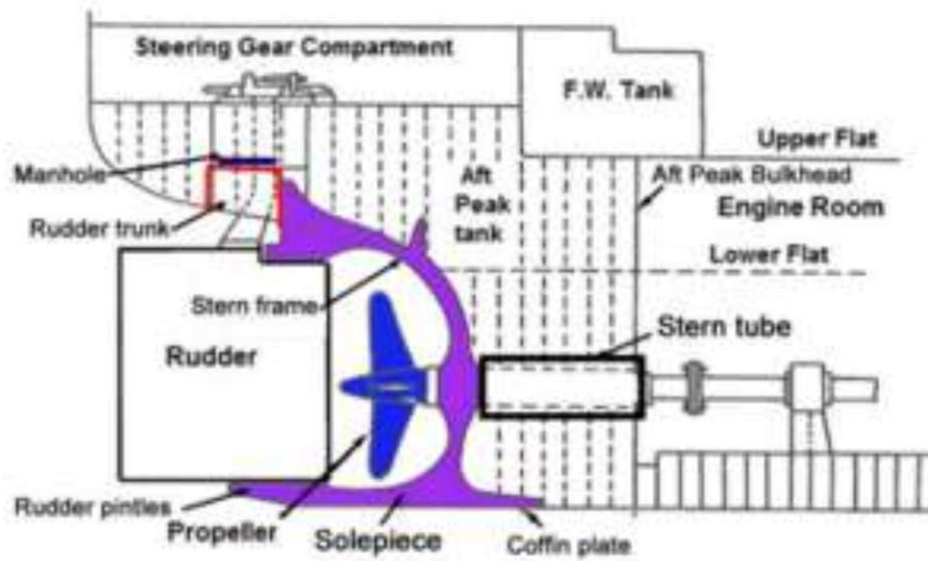
The arrangement, as the labelled drawing sets it out:
| Item | Function |
|---|---|
| Aft peak tank | The watertight compartment forward of the stern frame, around the stern tube |
| Stern frame | Terminates the shell plating aft, supports the rudder and the shaft |
| Sole piece | The fore-and-aft piece forming the lower part of the stern frame in a single-screw vessel |
| Rudder trunk | The passage in which the rudder stock is carried from the rudder to the steering compartment |
| Stern tube | The watertight tube enclosing and supporting the propeller shaft where it passes through the shell |
| Rudder | Steering, hung off the stern frame or a bearing arrangement |
| Propeller | Propulsion, on the tail shaft aft of the aperture |
| Aft peak bulkhead | The after boundary of the machinery space's watertight subdivision |
| Steering gear compartment | The space above, where the steering gear and the rudder carrier bearing sit |
| Upper flat, lower flat | The flats within the after body, giving access and carrying the structure across |
| Coffin plate | Connects the stern frame to the flat plate keel (Part 6 §6.7.2) |
9.1.4 The aft peak bulkhead
The after peak is located well aft, so that if the aft peak tank gets flooded due to damage to the hull, it would not cause excessive trim of the ship by the stern, because the amount of water entering the damaged compartment would be limited.
That is the same logic as the collision bulkhead at the other end and it uses the same geometry: a compartment at the extreme end of the ship has a small volume, and flooding it produces a trimming moment proportional to the distance from the centre of flotation. Keeping the compartment small, by placing its after boundary as far aft as the structure permits, is what keeps the trim within limits if it floods. The aft peak bulkhead's extension rule — it need only extend to the first deck above the load waterline, if it forms a watertight flat — is Part 7 §7.4.5.
9.1.5 The aft end in a twin-screw ship
In a twin-screw ship the shafting passes through the shell twice, once on each side, and both shafts leave through their own stern tubes. The consequences for the structure are the ones that distinguish the twin-screw after end:
- There is no need for an aperture in a stern frame on the centreline, because there is no single central propeller to operate in it. The stern frame either disappears or loses its main purpose, and the after form is built around the two shafting positions.
- Each shaft has its own bossing or tube where it leaves the shell, so there are two watertight penetrations of the after body to design, not one.
- The twin-screw arrangement calls for bossings on the quarters — the faired local projections over the shaft exits, which exist to give the shaft an efficient entry through the shell and to carry the shell plating past the shaft without an abrupt break.
- The semi-balanced rudder is often found in twin-screw ships — the type itself is a twin-screw habit.
9.2 Stern form
9.2.1 Two types of stern construction, drawn
Two main types of stern construction have been used to date:
- The cruiser stern.
- The transom stern.
And the wider set: elliptical, cruiser, and transom.
9.2.2 The cruiser stern
Character: a spoon-shaped stern used on most merchant ships, designed to give maximum immersed length. Further:
- Designed to lower the steering gear below the armour deck.
- Characterised by an upwardly curved profile from the aft perpendicular to the main deck.
- Cutaway for rudders occurs above the waterline.
- More pleasant profile and hydrodynamically efficient.
The construction, and why it is built the way it is:
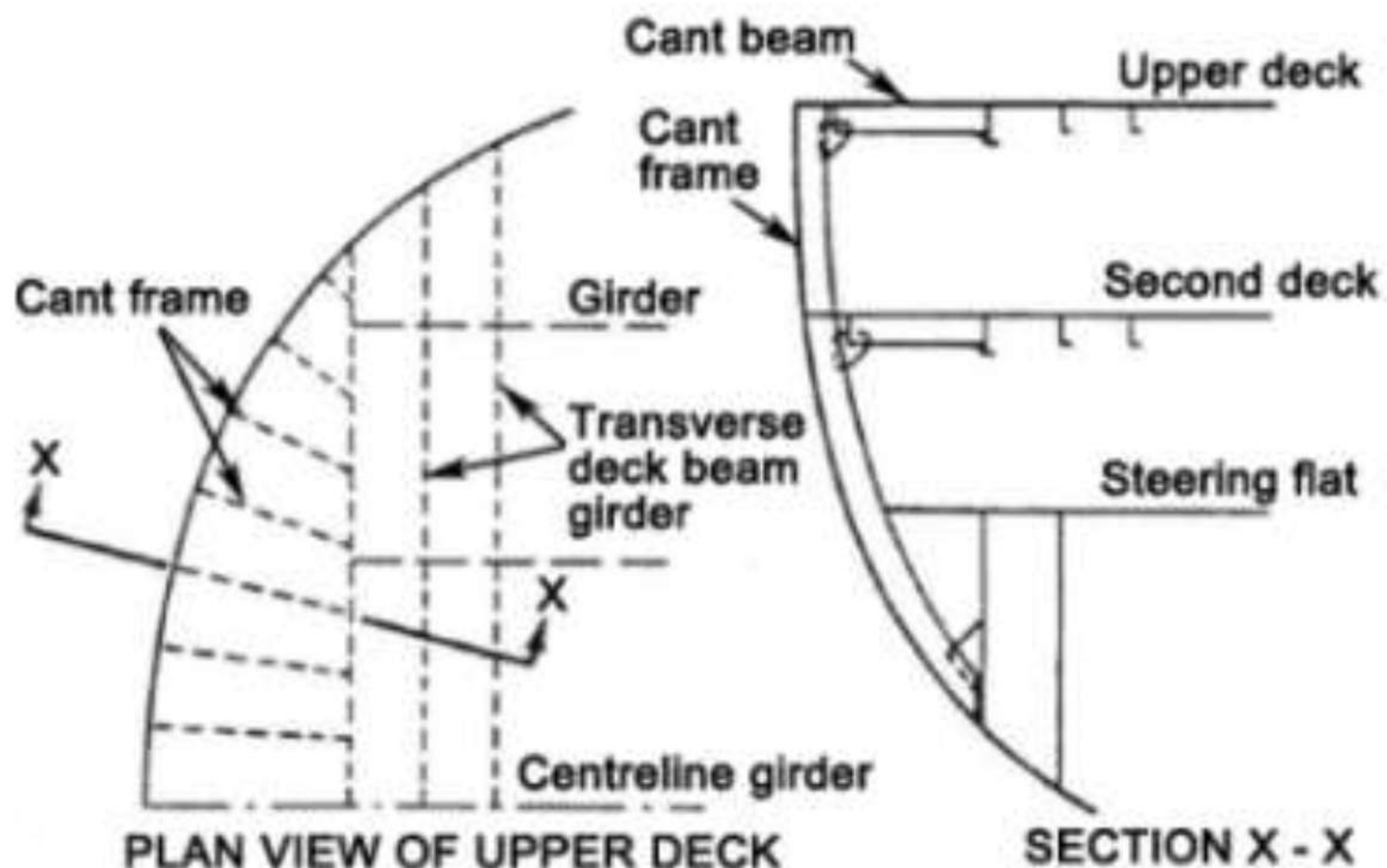
As the cruiser stern overhang may be subjected to large slamming forces, the construction of the cruiser stern ensures adequate resistance to any pounding stresses which may occur.
The members that do it:
| Member | Arrangement |
|---|---|
| Solid floors | Fitted at every frame space |
| Heavy centreline girder | Fitted below the upper deck, second deck and steering flat in the stern |
| Centreline web | A continuation of the centreline girder, fitted to the after end shell plate and running down to the centreline girder in the flooring region |
| Cant frames | Special frames, radiused around the after end; they are set at an angle to the centreline of the ship |
| Cant beams | Fitted at the tops of the cant frames, lying at an angle to the centreline |
| Horizontal stringers | May also be fitted to stiffen up the structure by connecting it to the transverse frames further forward |
And the same account in the compact form:
Solid floors are fitted at every frame space, and a heavy centreline girder is fitted right aft at the shell and decks. The stern plating is stiffened by cant frames or webs with short cant beams supporting the decks, and led to the adjacent heavy transverse deck beam. Further stiffening of the plating is provided, or adopted in lieu of cant frames, by horizontal stringers extending to the first transverse frame.
The condition of the type today:
The cruiser stern is rarely used in modern construction, but it is still to be seen in a large number of ships at sea.
9.2.3 The transom stern
Character: a square-ended stern used to provide additional hull volume and deck space. In the shorter form:
- Characterised by a generally flat shape extending to the waterline.
- Greater deck area and of simple construction.
- Can be viewed as a cruiser stern whose aft-most portion is cut off.
Transoms may be:
- Flat or curved
- Vertical, raked forward
- Raked aft
The construction:
Cant frames are not required where the transom stern is adopted. A transom is the surface that forms the stern of a vessel.
| Member | Arrangement |
|---|---|
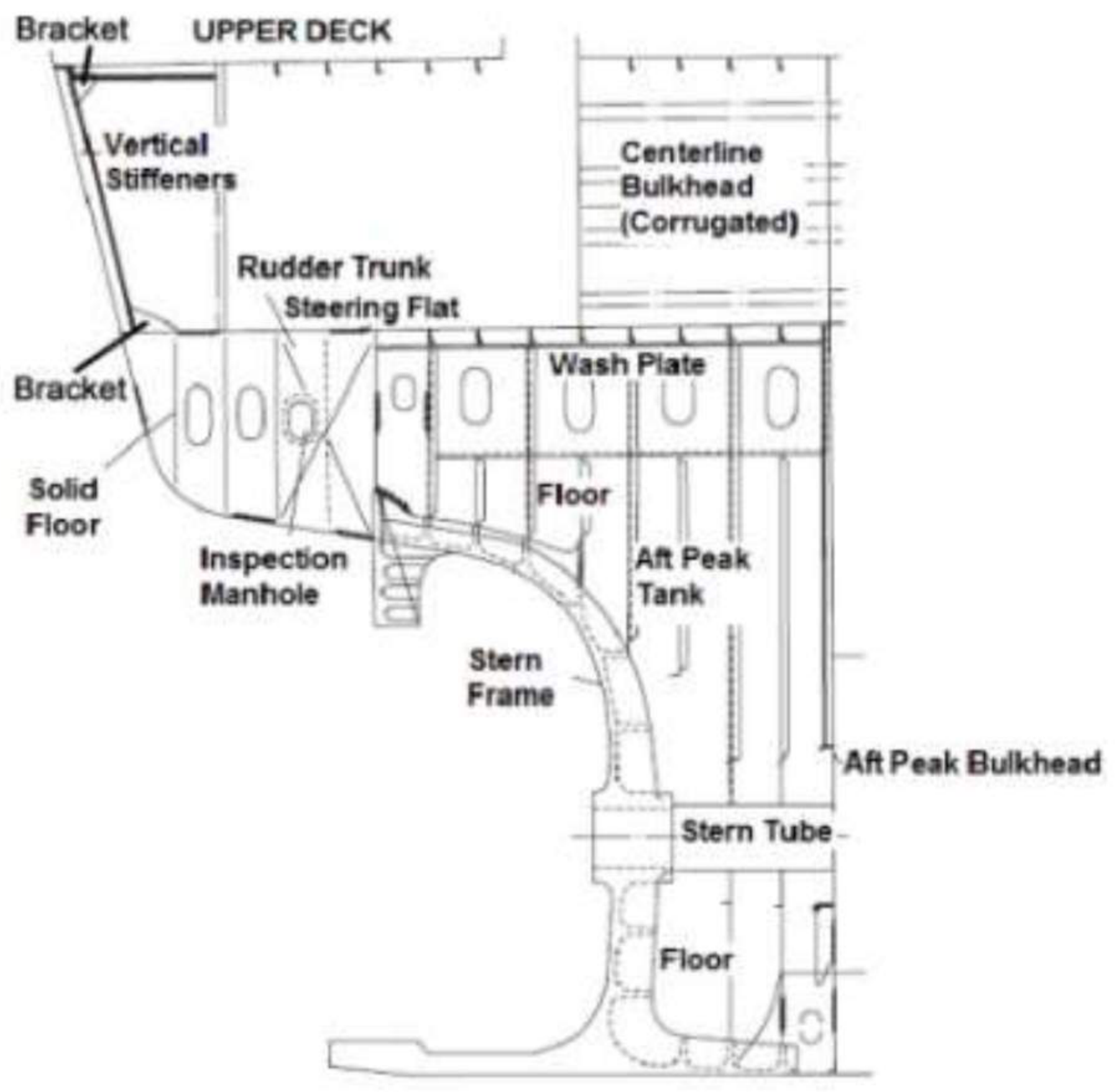
| Vertical stiffeners | The flat plate of the transom stern allows the use of vertical stiffeners around the shell plating; these are bracketed to the solid floor and to the deck beams running transversely across the stern |
| Deep horizontal stringer | Can provide additional stiffening to the shell plating if required |
| Deep shell centre girder | Runs beneath each of the decks at the stern, and is bracketed to the deep web at the centreline of the after shell plating |
| Centreline web | Bracketed to the various floors in the stern and finally to the solid-plate floor construction below |
And the trade the form makes: the stern is flat, which reduces the production costs, while at the same time reducing the bending moment on the after structure.
That one line is the comparison in miniature. The cruiser stern is expensive to build and carries a large bending moment because the overhang is long and unsupported; the transom stern is cheap and flat, which reduces the moment at the cost of the efficiency and the immersed length the cruiser form was designed to give.
9.2.4 Cruiser against transom
| Cruiser stern | Transom stern | |
|---|---|---|
| Form | Spoon shaped; upwardly curved profile from the aft perpendicular to the main deck | Square ended; generally flat, extending to the waterline |
| Gives | Maximum immersed length | Greater hull volume and deck space |
| Framing | Cant frames radiused round the after end, with cant beams | Cant frames not required; vertical stiffeners on the flat plate |
| Build cost | Higher | Reduced production cost |
| Bending moment aft | Large — the reason for the heavy centreline girder and solid floors at every frame | Reduced |
| Slamming | The overhang is subject to large slamming forces, answered by the heavy girder and web | Flat stern plating with vertical stiffeners and deep floors |
| Modern use | Rarely used in modern construction, but still seen in large numbers at sea | Common |
9.2.5 The elliptical stern
The most conventional form of stern, characterised by an upwardly curved profile beginning fore of the aft perpendicular, with the cutaway for rudders occurring above the waterline.
The distinction from the cruiser is where the profile begins: the elliptical stern curves up from fore of the aft perpendicular, the cruiser from the aft perpendicular itself to the main deck. The elliptical form is therefore the older, tamer profile — the after body carries its curvature through the region of the propeller rather than rising into the pronounced spoon of the cruiser.
9.2.6 SWATH — small waterplane area twin hull
SWATH stands for small waterplane area, twin-hull vessel. Twin torpedo-shaped hulls are fully submerged, with streamlined fins or struts supporting the upper platform or deck. It is used for passenger carrying and research vessels because it provides a stable platform.
SWATH belongs in this part because it is the extreme answer to the question the stern forms are arguing about. A conventional hull derives its stability from the waterplane area of a single form; SWATH deliberately removes the waterplane by putting the displacement volume deep in two submerged bodies, and then obtains stability from their separation. The result is a vessel whose motion in a seaway is a fraction of a conventional ship's — which is exactly what a research vessel or a passenger ferry in exposed water needs, and why the type is not general-purpose.
9.3 Stern frames and framing
9.3.1 What a stern frame is
The shell plating at the after end is terminated by the stern frame. The form of the stern frame is influenced by the stern profile and rudder type.
In single-screw ships the stern frame has a boss on the centreline for the tail shaft to pass through, and an adequate aperture is provided for the propeller to operate in.
9.3.2 The functions of a stern frame
Taken as a list, because this is a standard question and the list is the answer:
| Function | Detail |
|---|---|
| Support the rudder bearing | The lower bearing of the rudder, or the pintles |
| Support the propeller and shaft | The boss, and the shaft where it leaves the hull |
| Reduce vibration stresses | A major problem at the stern, and the stern frame plays an important role in handling it |
| Give streamlining to the stern | To prevent eddies that increase hull resistance |
| Close the shell plating at the stern satisfactorily | The shell must terminate somewhere, and the frame is where |
| Connect the keel to the rest of the ship's structure | Via the coffin plate and the flat plate keel |
| Support the upthrust at the stern in dry dock | The upthrust when taking the blocks |
The dry-dock item is the one usually forgotten. The stern frame is the structure that meets the aftermost docking block and takes the ship's weight there, which is why its scantlings are set by grounding and docking as well as by steering.
The overall size driver:
To prevent serious vibration at the after end of the ship, there must be adequate clearance between the blade tips of the propeller and the stern frame, and this will to a large extent dictate the overall size of the stern frame.
So the frame is not sized by strength alone. It is sized by the tip clearance the propeller needs to run without setting up vibration in the shell around it — the same requirement that appears in Part 4 §4.5 and Part 9 §9.27.
The lower part of the stern frame may provide a support for the rudder post, or for the rudder pintles.
9.3.3 How the stern frame is attached
Stern frame is a complete piece which is cast, forged or fabricated using steel plates and sections via cantilever beams.
The cantilever relationship is the thing to notice. The stern frame is not carried on a bulkhead — it projects aft from the shell, held only where it is welded to the shell and the keel and where its members run into the floors and the centreline girder of the after body. Every load it takes, thrust, rudder force, propeller weight, dry-dock upthrust, arrives at a member that is supported at one end only, and that is why the after-end framing is as heavy as it is. The members that share the load are the ones from §9.1.3: the sole piece, the coffin plate to the keel, the centre girder, the solid floors, and the centreline web at the after end shell.
9.3.4 Cant frames
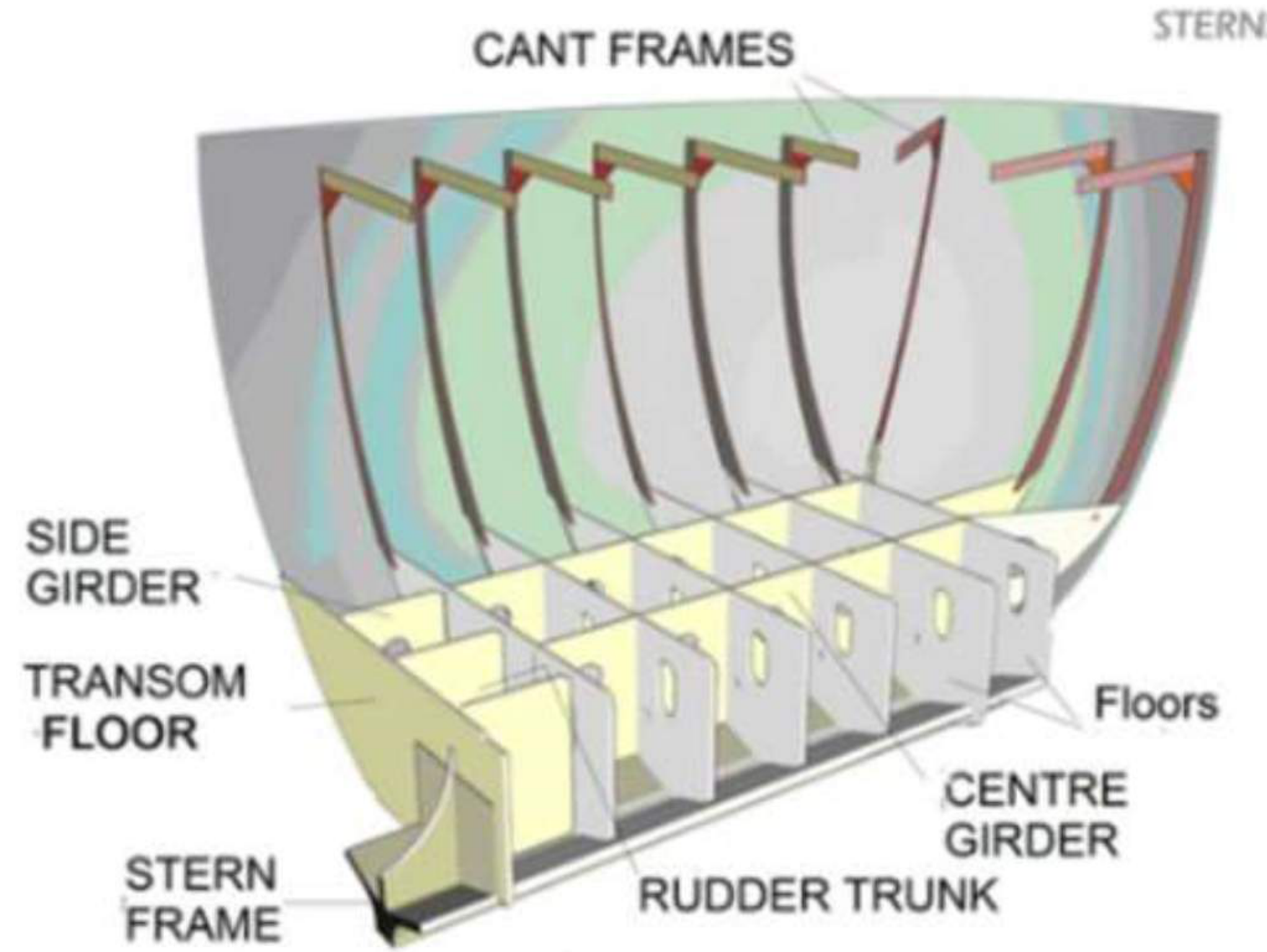
Special frames are radiused around the after end and are known as cant frames, since they are set at an angle to the centreline of the ship.
A cant frame is one which is set at an angle to the centreline of the ship. Such frames are fitted 610 mm apart, thus dividing the perimeter of the cruiser stern into small panels.
They belong specifically to the cruiser stern, where the after body curves in plan and the frames must follow the curve. Where they are fitted and what happens to them:
- All frames forward of the forward perpendicular are identified by capital letters starting with "A", and all frames aft of the aft perpendicular are identified with double capital letters starting with "AA".
- The frames between the forward and aft perpendiculars are identified with numbers, the forward perpendicular being number zero (0). Each frame aft of the forward perpendicular carries the next higher consecutive number; the last numbered frame is the aft perpendicular.
9.3.5 Cant beams
At the top, the cant frames are bracketed to cant beams, which also lie at an angle to the centreline.
Their connection:
- The forward ends of the cant beams are connected to a deep beam extending right across the ship.
- At the lower ends, the cant frames are connected to a solid floor.
That is what makes the cant frame arrangement a system rather than a set of loose members. The frame at the bottom lands on a solid floor; at the top it lands on a cant beam; and the cant beams all run forward to a deep transverse beam across the ship. The whole after overhang is therefore tied back to the main body of the hull through that one deep beam, and the load path is complete: shell → cant frame → cant beam → deep transverse beam → main hull.
9.3.6 Canted beam
A canted beam is the beam of that system seen in terms of the deck it supports — a beam lying at an angle rather than square across the ship, following the curve of the after body in plan. It is the deck-level member that the cant frame is bracketed to at its head, and the pair of names should be kept together: the frame is the vertical member hanging down the shell, the beam is the transverse member under the deck, and both are canted because both follow the same plan curve.
9.3.7 Transoms and transom floors
A transom is the surface that forms the stern of a vessel. It may be flat or curved, vertical, raked forward, or raked aft.
The transom floor is the floor in way of the transom. In the cruiser stern drawing it appears among the structural components of the after end, and in the transom stern the vertical stiffeners around the shell plating are bracketed to the solid floor and to the deck beams which run transversely across the stern.
The transom space is a different thing and belongs with the rudder trunk:
It is situated in the steering gear room. Here you can find a manhole door near the rudder trunk. Its purpose is to inspect the rudder trunk condition, lubrication etc. You can enter inside this place for carrying out inspection in port only, and in calm weather or sea.
The restriction is the point of the answer. The transom space is a small compartment reached through a manhole, close to the top of a watertight penetration of the hull, and it is entered only in port and in calm weather — which is a recognition that the thing being inspected is the rudder trunk gland and that the consequence of disturbing it at sea is flooding.
9.3.8 Sole piece
The sole piece is the fore-and-aft piece forming the lower part of the stern frame in a single-screw vessel.
It is the member that carries the after end of the stern frame forward to meet the keel, and it is one of the pair of connecting plates that tie the stern frame into the hull. The other is the coffin plate, which connects the stern frame to the flat plate keel with the aft-most plate of the keel dished around the stern frame's extension.
The oxter plates complete the set at the after end: they are peculiarly curved plates fitted where the stern frame meets the overhang of the stern — the fairing at the junction between the frame and the shell of the overhang, which is a curved and awkward corner that no rectangular plate can close.
9.3.9 Aperture for the propeller
In single-screw ships the stern frame has a boss on the centreline for the tail shaft to pass through, and an adequate aperture is provided for the propeller to operate in.
The aperture is bounded by the stern frame itself, and it has three requirements on it which are worth separating:
| Requirement | Where it comes from |
|---|---|
| Adequate clearance between blade tips and the stern frame | To prevent serious vibration at the after end, and it largely dictates the overall size of the stern frame |
| Smooth water flow into and away from the propeller | The stated design purpose of the whole aft end |
| Strength to carry the rudder and the propeller | The frame is the support for both |
The three pull against each other, which is why the aperture is one of the most designed-about openings in the ship. Making it larger for tip clearance and smooth flow costs the frame material that carries the rudder; making it smaller for strength brings the blade tips close to the shell and puts the vibration back into the after body.
9.4 Shafting
9.4.1 Stern tube
The stern tube is a watertight tube enclosing and supporting the propeller shaft. It consists of a cast iron or cast steel cylinder fitted with bearing surfaces upon which the propeller shaft — enclosed in a sleeve — rotates.
Part 7 §7.4.5 gives the structural requirement from the bulkhead side: the stern tube must be enclosed in a watertight compartment formed by the stern frame and the after peak bulkhead, and the after peak bulkhead's plating must be doubled or thickened around the stern tube to resist vibration.
9.4.2 Shaft tunnel
When the machinery space is divided from the after peak by one or more cargo holds, the main shafting must be carried through the holds. A tunnel is built round the shaft to prevent contact with the cargo and to give access to the shaft at all times for maintenance, inspection and repair.
| Item | Requirement |
|---|---|
| Watertightness and extent | The tunnel is watertight and extends from the after machinery space bulkhead to the after peak bulkhead |
| Position | It is not necessary to provide a passage on both sides of the shaft, so the tunnel is built off the centreline of the ship, allowing a passage down the starboard side |
| Top | Usually circular, except in a deep tank, when it is more convenient to fit a flat top |
| Stiffeners | The tunnel stiffeners or rings are fitted inside the tunnel, although in insulated ships and in tunnels which pass through deep tanks, the rings are fitted outside |
| Connection | The rings may be welded to the tank top or connected by angle lugs; the plating is attached to the tank top by welding or by a boundary angle fitted on the opposite side of the plating to the stiffeners |
| Strength | The stiffeners and plating must be strong enough to withstand a water pressure without appreciable leakage in the event of flooding. The scantlings are therefore equivalent to those required for watertight bulkheads |
| Under the hatches | The tunnel top plating is increased by 2 mm unless wood sheathing is fitted |
| Removability | One of the side plates is arranged so that it may easily be removed, together with the stiffeners, to allow the main shafting to be unshipped |
| Services | The shaft tunnel is used as a pipe tunnel, with pipes carried along the tank top and a light metal walking platform fitted about 0.5 m from the tank top |
| Shaft support | The shaft is supported at intervals by bearings fitted on shaft stools |
Two details in that table carry the whole logic of the tunnel. The scantlings being equivalent to a watertight bulkhead's is what makes the tunnel part of the ship's subdivision rather than merely a cover: if the tunnel floods, it floods a watertight space and the ship keeps her compartments. And the easily removed side plate is what makes the tunnel serve the shafting: the shaft has to be able to come out of a space that was built round it.
9.4.3 Propeller shaft
The propeller shaft is bolted to the main engine flywheel, passing through the thrust block then along the shaft tunnel, where it is supported by the shaft bearings before passing through the stern tube to drive the ship's propeller.
| Item | Detail |
|---|---|
| Material | Forged steel, complete with coupling flanges |
| Machining | Machined leaving a larger diameter at the location of the shaft bearings; this section must have a fine finish to run within the white metal bearing |
| Coupling | The flange faces are accurately machined and the bolt holes reamed to accept fitted bolts; bolted together using high-tension bolting, tightened with hydraulic tensioning gear |
| Bearings | The supporting bearings are cast in two halves and are usually white-metal lined, with oil scrolls cut into them to distribute the splash lubrication. Ball-bearing shaft supports are now being used, but have been reported as noisy with a tendency to run hot |
| After-peak seals | In the after peak tank the shaft is provided with inboard and outboard seals; these contain a nitrile rubber or viton lip seal which seals against the bronze liner shrunk fit around the cast-iron propeller shaft |
Propeller drop, which follows from the seals:
After a few years the seal creates grooves on the liner, and it naturally loses sealing and sea water can easily find its way inside. This reduces the lubrication effect and creates wear of the bronze liner. Now, as there is enough clearance, the shaft will come down by a certain amount because of the propeller weight. This drop in the propeller shaft is termed propeller drop, and is measured by a poker gauge.
The chain of causation is worth keeping whole, because the drop is the symptom and it is not the fault. A worn seal lets water in; water washes out the lubricant; the liner wears; the clearance grows; and only then does the shaft drop under the weight of the propeller hanging on the end of it. Measuring the drop with a poker gauge is measuring the end of that chain, and it is why a drop outside limits means the seals and the bearing need attending to, not just the drop itself being adjusted.
9.4.4 Tail shaft survey in dry dock
The types of survey:
| Survey | What is done | Interval |
|---|---|---|
| Normal survey | The conventional process, in which the tail shaft is completely withdrawn | 5 years |
| Modified survey | Partial withdrawal of the shaft, sufficient to ascertain the condition of the stern bearing and the shaft in way | — |
| Partial survey | The propeller is backed off on any keyed shaft, and the top half of the cone is examined by an efficient crack-detection method | — |
What a partial survey covers:
- The removal of the key.
- The oil gland and seals are to be examined and dealt with as necessary.
- Wear-down is to be measured and found satisfactory.
- The propeller and fastenings are to be examined.
Tail-shaft condition monitoring (TCM):
Throughout the period, with required periodical monitoring and tests, the intervals between two consecutive withdrawals of the tail shaft may be extended to a maximum period of 10 years. In this case incomplete withdrawal of the tail shaft will not be required at the modified survey.
The information the condition-monitoring programme is built on:
- Water content in oil report
- Oil consumption record
- Forward and aft bearing temperature
- Particle analysis to be done
- Oil ageing — resistance to oxidation
- Previous survey report
- A spare seal is available on board
- A spare temperature sensor
And the outcome: upon analysis of the data the class may give an extension for survey up to 7.5 years. A tail shaft survey is carried out once in 5 years, or as per classification society rules.
The list is worth reading as the answer to why a survey interval can be extended at all. Each item is a proxy for the condition that the withdrawal would have revealed directly: water in the oil is the sea getting past the seal; oil consumption is where it went; bearing temperatures are the friction the wear produces; particle analysis is the metal the liner has lost; and oil ageing is whether the lubricant still protects. The surveyor is not guessing when he grants the extension — he is reading the evidence the monitoring has been collecting.
9.4.5 Shaft earthing device
It is a propeller shaft grounding device. Its function is to ground the static electricity to the ship's hull caused by propeller rotation.
The shaft is insulated from the hull at every point by the white-metal bearings, the oil films and the rubber lip seals of §9.4.3. That insulation is necessary for the shaft's own protection but it leaves the rotating shafting able to accumulate static charge generated by rotation. The earthing device gives the charge a deliberate path to the hull instead of letting it find its own — through a bearing, a seal or a person.
9.4.6 Propeller shaft alignment check
After the boat has been in the water for 24 hours, the engine alignment should be checked.
The delay is the substance of the instruction. A ship's hull and the machinery bedplates settle and take up a different shape once the hull is immersed, because in the water the hull is supported by buoyancy distributed along its length rather than by a set of blocks in a few places. Aligning the shafting on the ways, or immediately on floatation, aligns it to a shape the ship will not keep, so the check is made after the hull has taken up its afloat form.
9.5 Roll damping and anti-heeling
9.5.1 Methods of reducing rolling, taken as a set
Various methods of reducing rolling:
- Bilge keel
- Fin stabiliser
- Tank stabiliser — in its three forms: passive, controlled passive, and active controlled
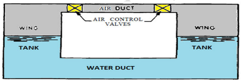
- Anti-rolling tanks, controlled by pumps or by air pressure — the same family
The fourth is stated in the oral form:
Anti-rolling tanks: they are similar to the principle of the passive tank system, but the movement of water is controlled by pumps or by the air pressure above the water surface. The tanks either side of the ship may be connected by a lower limb, or two separate tanks can be used.
9.5.2 Bilge keel as a roll damper
The bilge keel is a Part 6 §6.7.5 member, but its primary purpose is roll damping and it belongs in this list as the method that needs no machinery at all.
How it damps:
They are plates projecting from the turn of the bilge and extending over the middle half to two-thirds of the ship's length. They cause a body of water to move with the ship and create turbulence, thus dampening the motion and causing an increase in period and reduction in amplitude.
The historical note that explains why it exists:
When ships were first built of iron instead of wood, a bar keel was fitted, one of its advantages being that it acted as an anti-rolling device. With the fitting of the flat plate keel the anti-rolling properties were lost. An alternative method was supplied in the form of bilge keels, which are now used in the majority of ships.
The history is the reason the bilge keel exists and it is the neatest way to explain the mechanism: the bar keel of Part 6 §6.7.3 projected below the shell and acted as a fixed fin against the water, and when ships changed to a flat plate keel that projection disappeared. The bilge keels replaced the lost fin by putting projections out at the bilge — and putting them at the bilge rather than at the centreline is what gives them a lever arm about the roll axis, where a keel projection has very little.
The two factors deciding the depth are the Part 6 §6.7.6 pair: the web must be deep enough to penetrate the boundary layer of water travelling with the ship, and if it is too deep the force of water when rolling may cause damage. Bilge keels of 250 mm to 400 mm in depth are fitted to ocean-going ships, and the keels extend for about one half of the length of the ship amidships and are tapered gradually at the ends.
9.5.3 Fin stabiliser
How they work:
These work very much like an aircraft wing, in that they provide lift, positive or negative, depending upon their aspect relative to the water flow. Fins are of aerofoil cross-section and are provided with tail flaps which can be moved relative to the main fin. This is accomplished automatically as the main fin is rotated. Main fins usually have a maximum movement of 20 degrees up or down, whilst the tail can move a further 30 degrees relative to the main flap. Two fins extend from the ship's side at about bilge level. They are turned in opposite directions as the ship rolls. The forward motion of the ship creates force on each fin, and hence produces a moment opposing the roll. When the fin is turned down, the water exerts an upward force. When the fin is turned up, the water exerts a downward force.
| Item | Detail |
|---|---|
| Number and position | Two fins, extending from the ship's side at about bilge level |
| Section | Aerofoil, usually rectangular |
| Movement | About 20° for the main fin; tail fins turn a further 10–30° relative to the main fin |
| Direction | Turned in opposite directions as the ship rolls |
| Actuation | An electric motor driving a variable delivery pump, delivering oil under pressure to the fin tilting gear; the oil actuates rams coupled through a lever to the fin shaft |
| Retractability | Most fins are retractable, either sliding into fin boxes transversely or hinged into the ship. Hinged fins are used where there is a restriction on the width of ship, such as in a container ship |
The essential limitation is stated by the mechanism itself: the fins depend on the forward motion of the ship to create the flow over them. A fin stabiliser therefore stops working when the ship stops, and cannot help a vessel that spends its time stationary or at very low speed — which is precisely the case the tank stabilisers in §9.5.4 are for.
9.5.4 Tank stabiliser
Three basic systems of roll damping using free surface tanks:
- (a) Passive tanks
- (b) Controlled passive tanks
- (c) Active controlled tanks
And the reason they exist at all:
These systems do not depend upon the forward movement of the ship, and are therefore suitable for vessels such as drill ships. In introducing a free surface to the ship, however, there is a reduction in stability which must be considered when loading the ship.
(a) Passive tanks
- Two wing tanks are connected by a duct having a system of baffles.
- The tanks are partly filled with water.
- When the ship rolls, the water moves across the system in the direction of the roll. As the ship reaches its maximum angle and commences to return, the water, slowed by the baffles, continues to move in the same direction.
- Thus a moment is created, reducing the momentum of the ship and hence the angle of the subsequent roll.
- The depth of water in the tanks is critical, and for any given ship depends upon the metacentric height.
- The tank must be tuned for any loaded condition by adjusting the level, otherwise the movement of the water may synchronise with the roll of the ship and create dangerous rolling conditions.
- Alternatively the cross-sectional area of the duct may be adjusted by means of a gate valve.
(b) Controlled passive tanks
- The principle of action is the same as for the previous system, but the transverse movement of the water is controlled by valves operated by a control system similar to that used in the fin stabiliser.
- The valves may be used to restrict the flow of water in a U-tube system, or the flow of air in a fully enclosed system.
- The mass of water required in the system is about 2 per cent to 2.5 per cent of the displacement of the ship.
- With correct design of tank, the water oscillating period will equal the roll period of the ship, but its motion will lag behind that of the ship by one quarter of the roll period, and behind the wave by half of the roll period. Water in the tank thus opposes the wave action producing the roll. Water movement between the tanks is regulated to some extent by the air valves.
- With the valves closed the system is put out of action.
(c) Active controlled tanks
- In this system the water is positively driven across the ship in opposition to the roll. The direction of roll, and hence the required direction of the water, changes rapidly.
- It is therefore necessary to use a uni-directional impeller in conjunction with a series of valves.
- The impeller runs continually, and the direction of the water is controlled by valves which are activated by the control system.
The three systems compared, on the one question that separates them:
| System | What moves the water | What sets the timing | Failure mode |
|---|---|---|---|
| Passive | The ship's own roll, through the duct and baffles | The tank's tuned water level, which must be set for each loading condition | Can synchronise with the roll and make it worse |
| Controlled passive | The ship's roll, restricted by valves | The valve setting — a control system like the fin stabiliser's | Valves closed, system out of action |
| Active | A constantly running impeller, directed by valves | The rapid change of roll direction | Requires power; the impeller runs continuously |
The critical detail — the tuning of the passive tank — is the one that makes the passive system genuinely dangerous if it is not maintained,: the water level is critical, it depends on the metacentric height, it must be tuned for any loaded condition, and if it is not, the movement of the water may synchronise with the roll of the ship and create dangerous rolling conditions.
The controlled passive system is what solves that. The physics is the same, but the design condition is stated precisely: the water oscillation period equals the roll period, but lags the ship by one quarter of the roll period and the wave by half a roll period. A quarter-period lag is the phase that produces maximum damping — the water is by then moving against the roll rather than with it. The valves exist so that the phase can be held at that condition, and the valves closed put the system out of action — which is the safe state, because a tank that is not oscillating cannot synchronise with anything.
9.5.5 Anti-heeling system
What it does and why it is fitted:
The anti-heeling system of a ship automatically detects the heeling angle of the ship and compensates the same. This allows the vessel to have continuous loading and unloading cargo operations without stopping in between for list correction, and saves a considerable amount of time in port.
The working:
- Ballast tanks are internally connected to each other by means of pipe lines, automatic valves and control systems.
- When the ship heels to any of the sides, the heeling sensor sends the signal for change of the ship's angle, with respect to the ship's upright position, to the master control panel.
- This change in heeling angle is compensated by auto-transferring the water from the heeled side to the other side of the ship, making the vessel upright.
- Level control switches are installed in the ballast tanks involved with the anti-heeling system, to avoid low level or overfilling and hence over-pressurising of the tanks.
The most common cause: out of the three reasons the ship heels — strong winds, hard and speedy turns, and uneven cargo loading — the most common cause is uneven cargo loading and unloading.
The distinction that must be kept clear. A tank stabiliser (§9.5.4) reduces ROLL — a continuous oscillation about the longitudinal axis, repeated every few seconds. An anti-heeling system removes a HEEL or LIST — a steady angle that does not return, and that arises from a persistent imbalance. The tank stabiliser's tanks are tuned to a period; the anti-heeling system's tanks are transferred between.
9.5.6 Pneumatic anti-heeling system
- This system comprises an air purging arrangement and regulating valve system to force air on top of the ballast tank.
- The air is forced into one tank and purged from the other, making the water rapidly flow from the pressurised tank to the purged tank.
- This transfer of water is used to upright the vessel in quick time.
The mechanism is worth stating as a pressure difference, because that is what makes it fast. The two tanks are connected below the waterline; the flow between them is driven by the difference in pressure at their surfaces. Raise the pressure in one and lower it in the other and water moves from the higher to the lower — with no pump in the water path at all, which is why the transfer is rapid and why the system has no moving parts in contact with the ballast.
9.5.7 Water pump anti-heeling system, and its advantages and safeties
The system:
The pump system consists of an electrical motor-driven water pump, which can be a reversible or non-reversible pump, connected with remote-controlled valves that can direct ballast water flow between the tanks.
The advantages:
- Allows safer and rapid cargo loading and unloading.
- Shortens harbour time and saves port dues.
- Reduces damage to ramp, rolling cargo and containers.
- Ensures safety of the ship and personnel.
The safety: limit switch only.
The two systems compared:
| Pneumatic | Water pump | |
|---|---|---|
| What moves the water | Air pressure difference | A pump |
| Components in the water path | None — no moving parts in contact with the ballast | An impeller, and the valves that direct it |
| Speed | Rapid — "in quick time" | Depends on the pump |
| Safeguard | Level control switches, to avoid low level or overfilling and over-pressurising | Limit switch only |
The "limit switch only" is the one striking line in the comparison and it is worth stating as it stands, because it shows how slight the interlocking on the pump system is. The pneumatic system's protection is inherent in its principle — you cannot over-pressurise a tank by purging air from it — whereas the pump system can keep pumping into a tank that is already full, which is what the limit switch is there to stop.
9.6 Summary — what the aft end has to answer
| Load or duty | Fails by | Where it acts | What answers it |
|---|---|---|---|
| Slam loading on the counter | Structural damage to the overhang | The after body, above and below the waterline | Solid floors at every frame space, heavy centreline girder and web, cant frames and beams, horizontal stringers |
| Rolling | Discomfort, cargo shift, cargo damage | The whole ship | Bilge keels; fin stabiliser when under way; tank stabiliser when not |
| Heeling from uneven cargo | List during cargo operations | The whole ship | Anti-heeling system, pneumatic or pump |