
Ship Types, Hull Form and the Parts of a Ship
The cargo ship types an examiner asks for by name, then the hull form and the plating, strakes and deck parts that name every piece of the hull.
Key Principles at a Glance 8 points
- Preliminary design settles six things before any structure is drawn — dimensions, displacement, stability, propulsive characteristics and hull form, general arrangement, and principal structural details — and every later decision follows from them.
- Container capacity is counted in TEU and FEU, the 20- and 40-foot equivalent units, carried in cellular holds and stacked on the hatch covers and upper deck.
- Under the IBC Code a chemical tanker is built to Type 1, 2 or 3 according to the hazard of its cargo, which fixes both where the cargo tanks may sit and how large they may be.
- Camber is the transverse curvature of a deck and sheer is the longitudinal rise of a deck towards the ends; both exist to shed water and to add buoyancy where the ship ends.
- A strake is a continuous line of shell plating. The garboard strake lies against the keel and the sheer strake is the top line of shell at the strength deck, and both are worked heavier than the plating between them.
- Rise of floor and bilge radius describe the turn of the bilge; tumblehome is shell that falls in above the waterline, flare is shell that opens out, and the two are opposites.
- Scantlings are the dimensions and thickness of rolled sections and the breadth and thickness of plating and their spacing — they are what a classification rule actually specifies.
- The margin line is drawn at least 76 mm below the upper surface of the bulkhead deck at the side, and a damaged ship is judged safe only while no part of that line is immersed.
1.1 Ship types and the design inputs
What a ship is, what it is called, and how its parts are named. The principal dimensions and reference points are not in this part — they are in Part 1b, because the lines from which a ship is measured are a different subject from the types of ship and the names of their parts.
1.1.1 What the preliminary design has to fix
Before any structure is drawn, the preliminary design of a vessel due for construction settles six things. Every later decision — scantlings, framing, tank layout — follows from them:
- Dimensions
- Displacement
- Stability
- Propulsive characteristics and hull form
- Preliminary general arrangement
- Principal structural details
The type of ship plays the decisive role in fixing all six. Cargo ships are classified by purpose, size and type of cargo, and the economic factor is of prime importance — an owner wants maximum return on investment, so a ship's construction depends not only on current economic necessity but on future adaptability.
1.1.2 Container ships
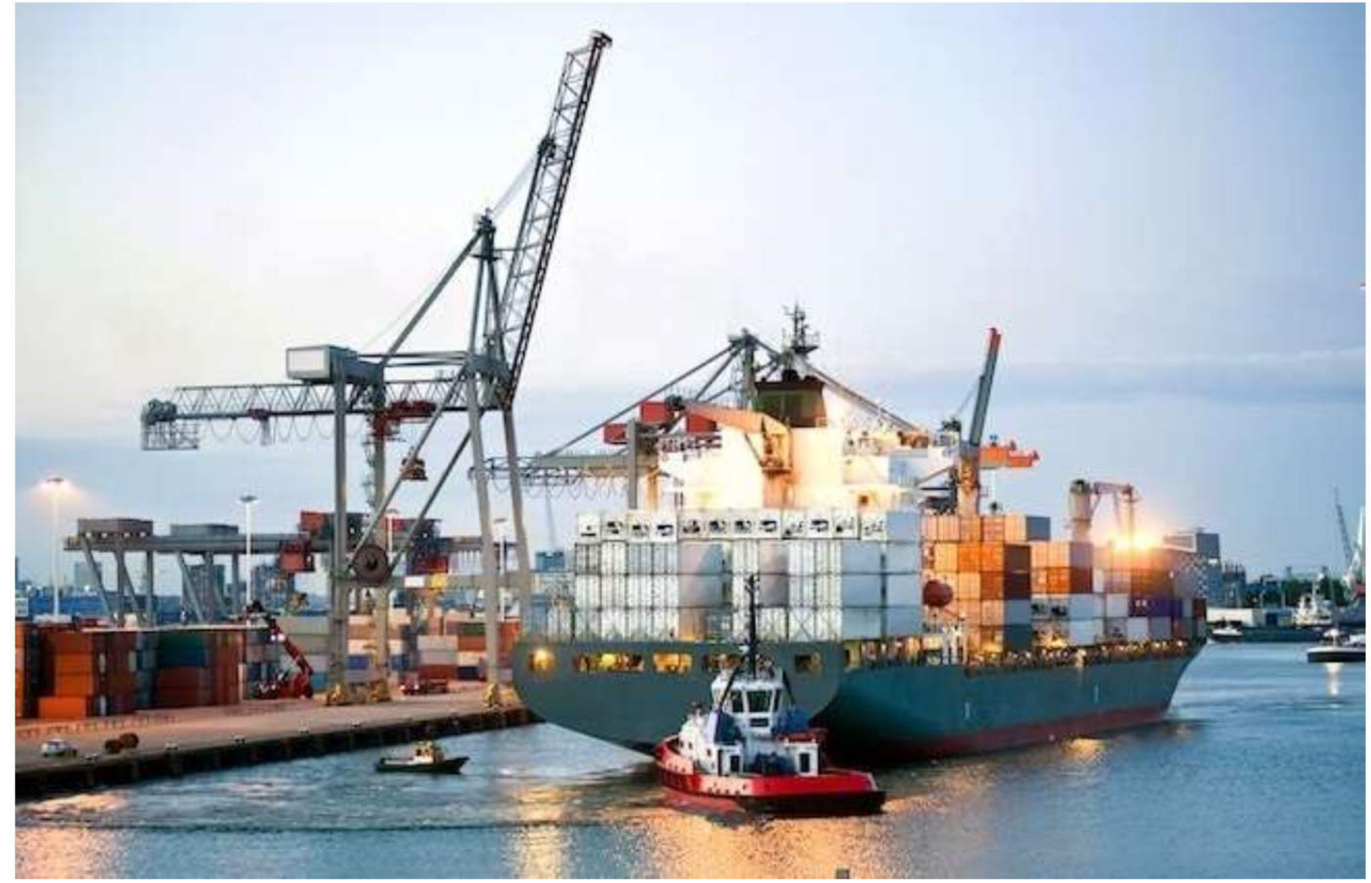
Container ships carry most of the world's manufactured goods and products, usually on scheduled liner services. They transport a combination of two standardised container sizes known as 20- or 40-foot equivalent units, abbreviated TEU and FEU. The containers are carried in cellular holds and stacked on the ship's hatch covers and upper deck. Contents may be non-perishable or perishable, the latter often carried in refrigerated containers.
By size, container ships are classed as Panamax, Suezmax, Post-Panamax, Post-Suezmax and Post-Malaccamax.
1.1.3 Bulk carriers
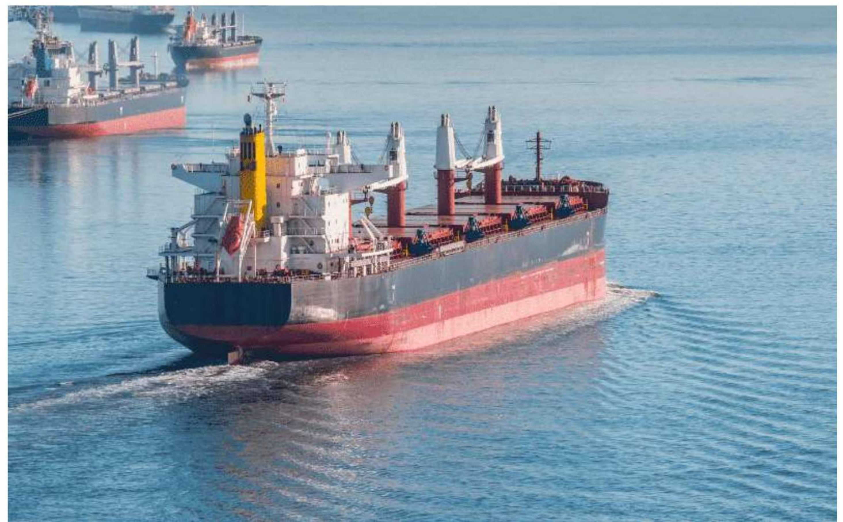
Bulk carriers transport cargo, generally dry cargo, in bulk quantities. The cargo is loose — without any specific packaging — and is typically food grains, ores, coal, or cement.
The recognised sub-types are conventional bulkers, geared bulkers, gearless bulkers, self-discharging bulkers, Lakers and BIBO (bulk-in / bag-out).
Two dry-cargo trading patterns are worth separating at this point:
- Tramp — a ship engaged in the tramp trade has no fixed schedule and no published ports of call.
- Cargo liner — an ocean liner designed to transport passengers from point A to point B. The classic example is a transatlantic crossing from Europe to America.
1.1.4 Tankers
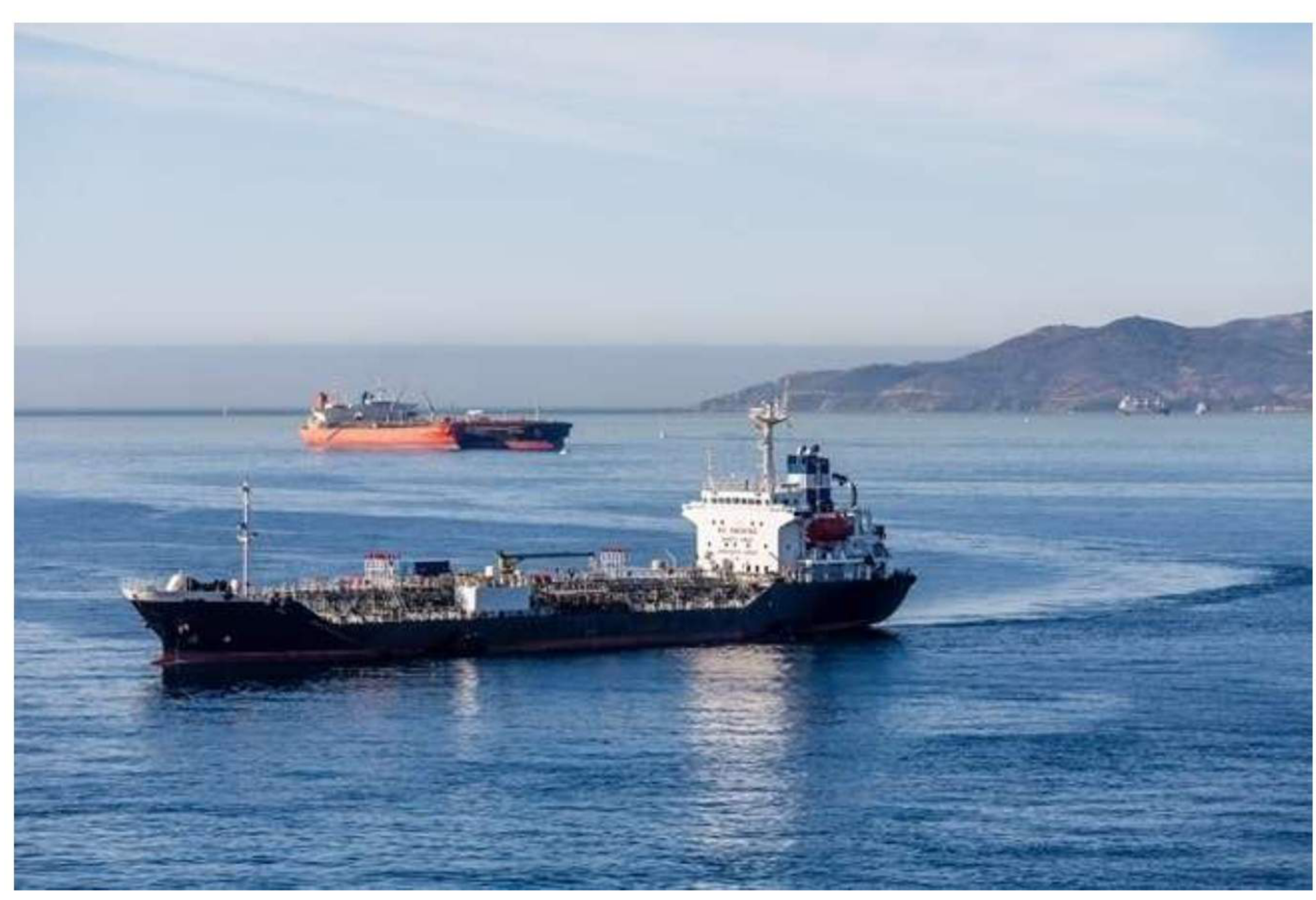
Tanker ships are specialised vessels for carrying a large amount of liquid cargo, subdivided by the cargo they carry:
- Oil tankers — mainly crude oil and its by-products.
- Liquefied gas carriers — designed to transport LPG, LNG or liquefied chemical gases in bulk.
- Chemical and product carriers — designed to transport chemicals and different liquid products in bulk.
- Other tankers — juice tankers, wine tankers, integrated tug barges.
By size, tankers are further divided into VLCC, ULCC, Panamax, Aframax, Suezmax, Capesize, Handymax, Lighters and Handy.
1.1.5 Roll-on / Roll-off ships
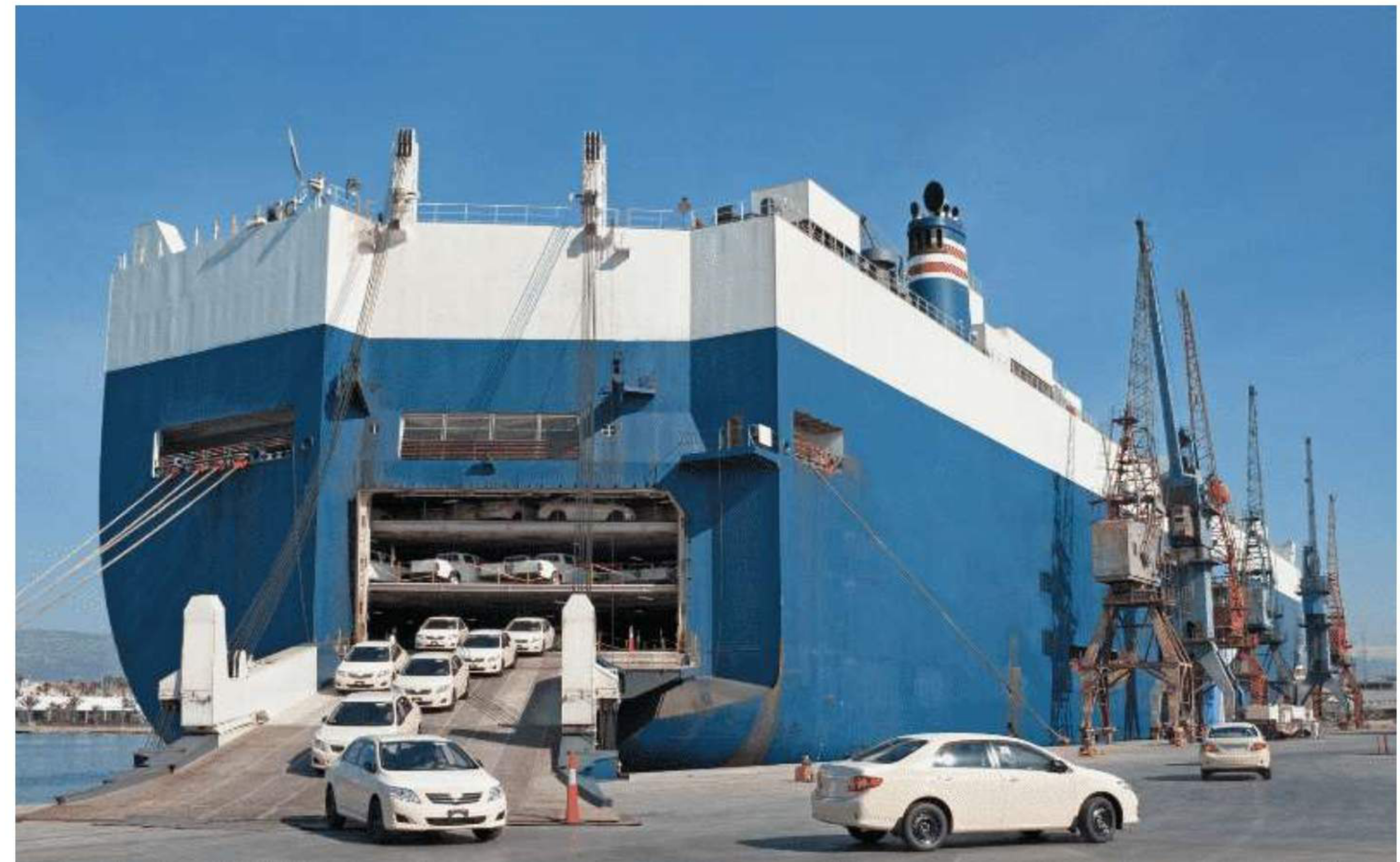
Ro-Ro is an acronym for Roll-on/roll-off. These are vessels used to carry wheeled cargo. The recognised variants are:
- Pure Car Carrier (PCC) and Pure Car and Truck Carrier (PCTC)
- Container Vessel + Ro-Ro (ConRo)
- General Cargo + Ro-Ro (GenRo)
- RoPax
- Complete RoRo ships
1.1.6 Passenger ships
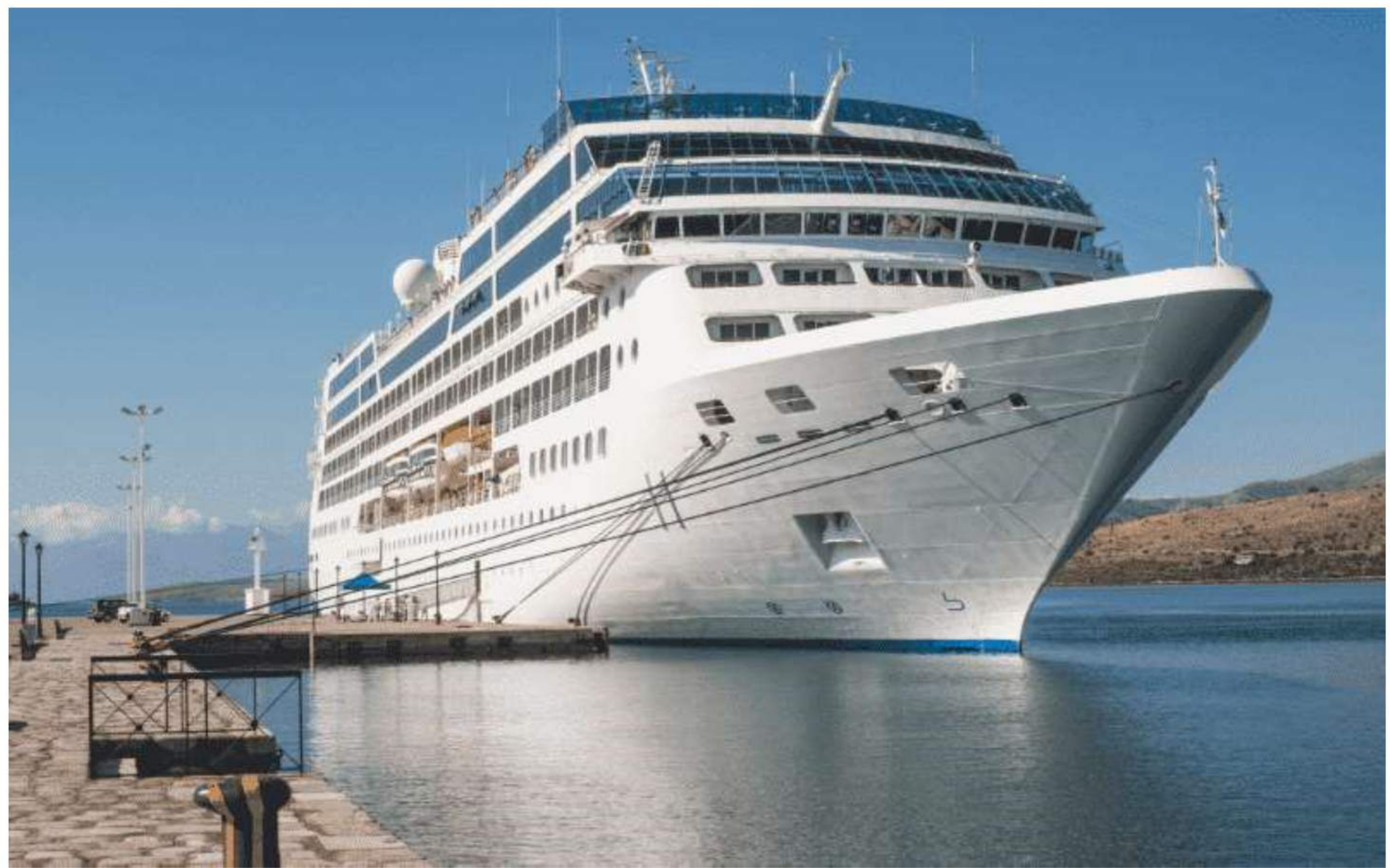
Passenger ships are mainly used for transiting passengers and are classified into ferries and cruise ships:
- Ferries — vessels used for transiting passengers (and vehicles) on short-distance routes.
- Cruise ships — mainly used for recreational activities; luxurious floating hotels with state-of-the-art facilities.
The further classification given is liners, cruise ships and pilgrimage ships; and, by route, cross-channel ferries, coastal ferries and harbour ferries. Cruise ships are additionally grouped as Arctic and Antarctic cruises.
1.1.7 Offshore vessels
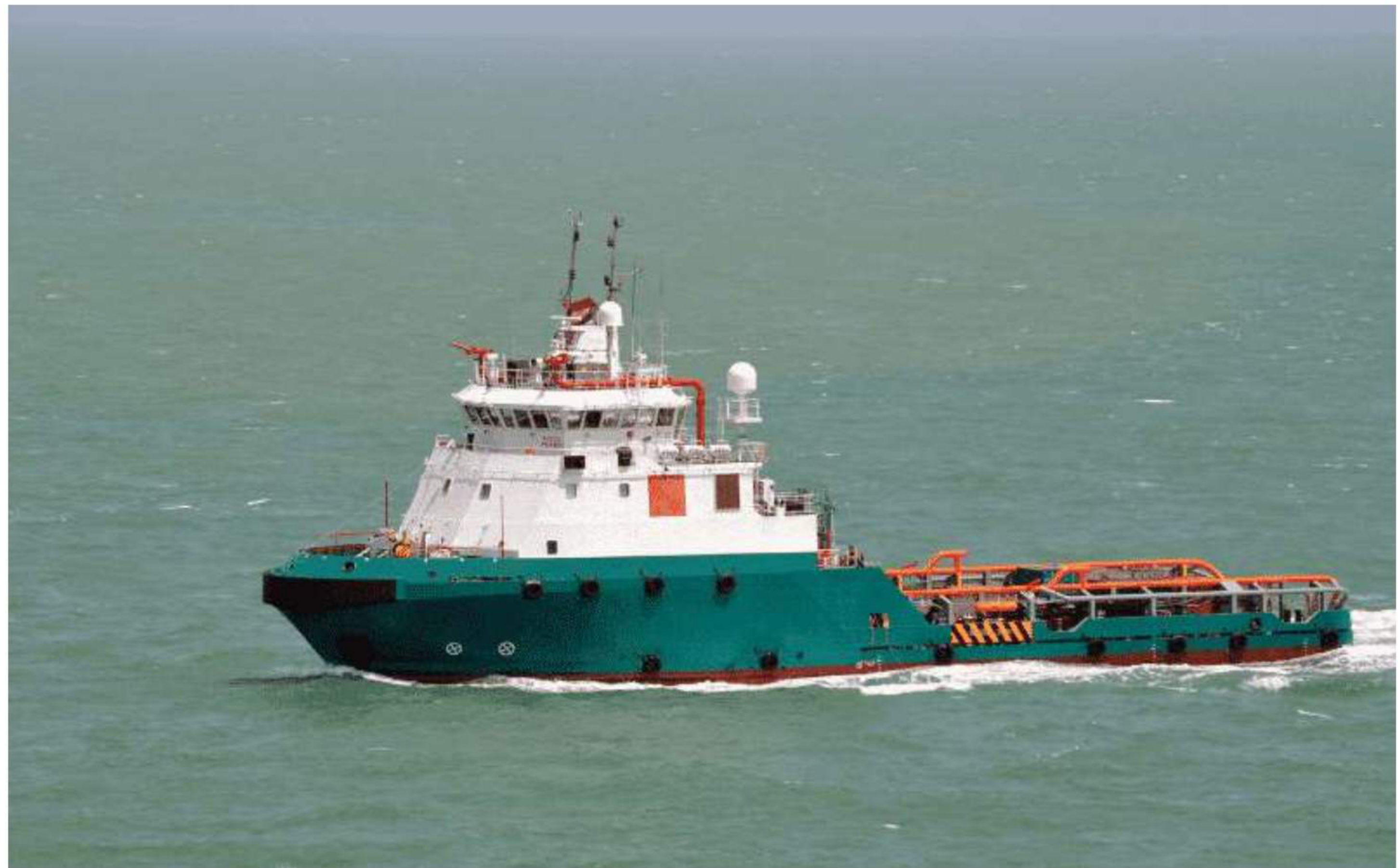
Offshore vessels mainly help in oil exploration and construction jobs at sea. The main types are:
- Supply ship — vessels that supply offshore rigs.
- Pipe layers — vessels engaged in laying pipes and cables.
- Crane barges or floating cranes — a ship with a crane specialised in lifting heavy loads.
- Semi-submersible drill rigs — mobile offshore drilling units forming stable platforms for drilling oil and gas.
- Drill ships — merchant vessels designed for exploratory offshore drilling of new oil and gas wells, or for scientific drilling.
- Accommodation barges — a stand-alone floating hotel, or accommodation plus space for cargo.
- Production platforms — to extract and process oil and natural gas, or to store product temporarily until it can be brought ashore for refining and marketing.
- Floating Storage Unit (FSU) — a floating vessel mainly used for storage of oil and by-products.
- Floating Production and Storage Unit (FPSO) — used by the offshore oil and gas industry for production and processing of hydrocarbons and the storage of oil.
- Anchor handling vessels — used for offshore construction and installation operations.
- Diving vessels — used by divers for underwater jobs.
1.1.8 Fishing vessels
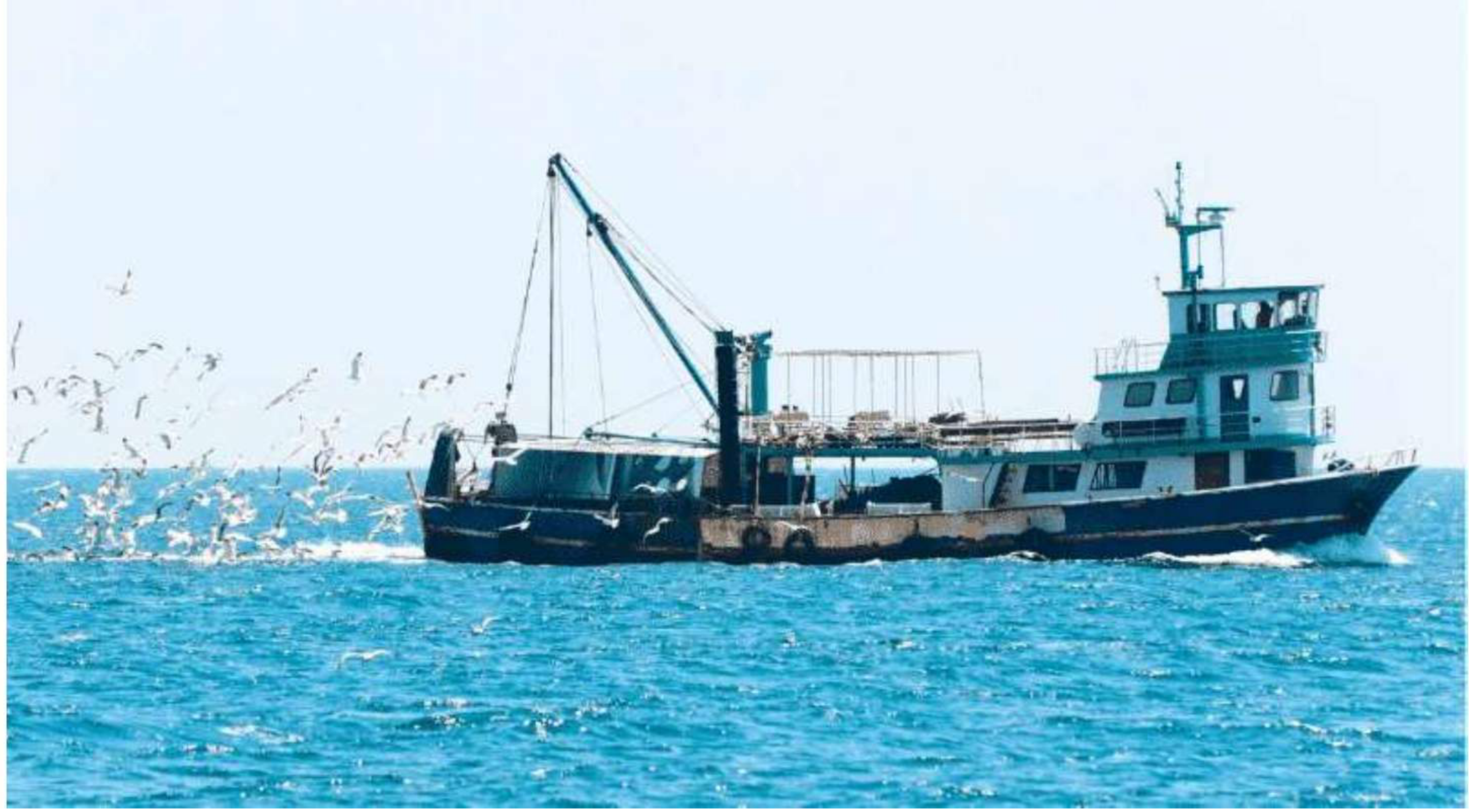
Ships or boats used for recreational or commercial fishing at sea are called fishing vessels, classified into two types: trawlers and non-trawling vessels.
- Trawlers and purse seiners — a fishing trawler, also known as a dragger, is a commercial fishing vessel designed to operate fishing trawls. Trawling involves actively dragging or pulling a trawl through the water behind one or more trawlers. A purse seine is a large wall of netting deployed around an entire area or school of fish; the seine has floats along the top line with a lead line threaded through rings along the bottom. Once a school of fish is located, a skiff encircles the school with the net.
- Factory ships — also known as a fish processing vessel; a large ocean-going vessel with extensive on-board facilities for processing and freezing caught fish or whales.
1.1.9 Specialty vessels
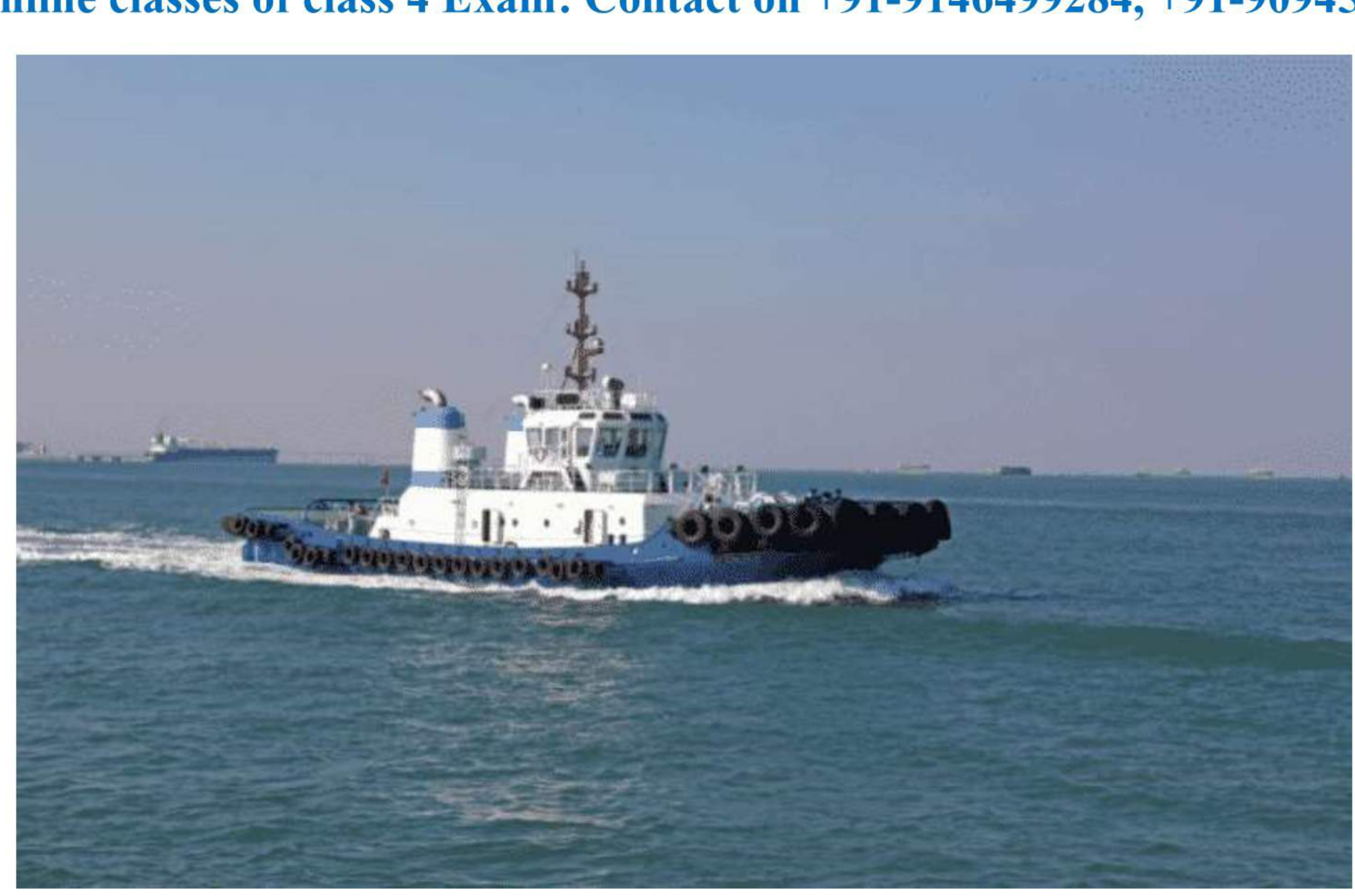
Specialty vessels are constructed and used for specific purposes:
| Vessel | What it does |
|---|---|
| Tug | Manoeuvres vessels by pushing or towing them |
| Tender | Services or supports other boats or ships, generally transporting people and/or supplies |
| Pilot craft | Transports harbour pilots |
| Cable layer | Lays cables onto the sea bed |
| Research vessel | Seismic, hydrographic, oceanographic and polar vessels |
| Salvage vessel | Recovery of lost property at sea |
| Lightship | Acts as a lighthouse, in waters too deep or otherwise unsuitable for lighthouse construction |
| Barge carrier | Carries barges — flat-bottomed boats built mainly for river and canal transport of heavy goods |
| Timber carrier | Carries timber |
| Livestock carrier | Carries livestock |
| Ice breaker | Cuts ice deposits in extremely cold climates to make waters navigational |
1.1.10 High-speed craft
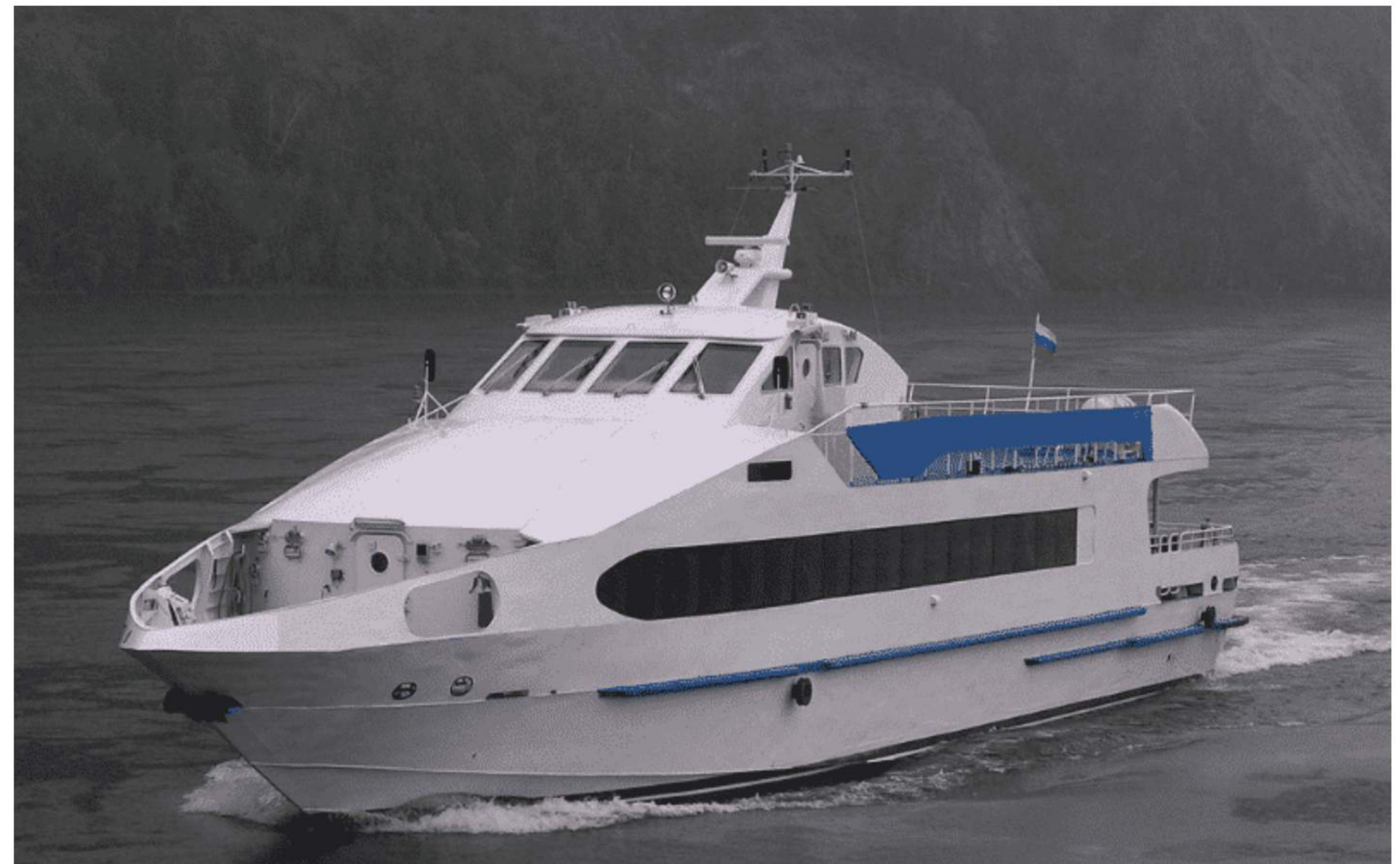
High-speed craft are a special type of technologically advanced high-performance marine vehicle. Most of these technologies are not used in commercial vessels, though a few have been successfully implemented and tested in small-scale conventional merchant vessels. The main types are:
- Multihulls, including wave piercers
- Small waterplane area, twin-hull (SWATH)
- Surface effect ship (SES) and hovercraft
- Hydrofoil
- Wing in Ground craft (WIG)
1.1.11 Dredgers
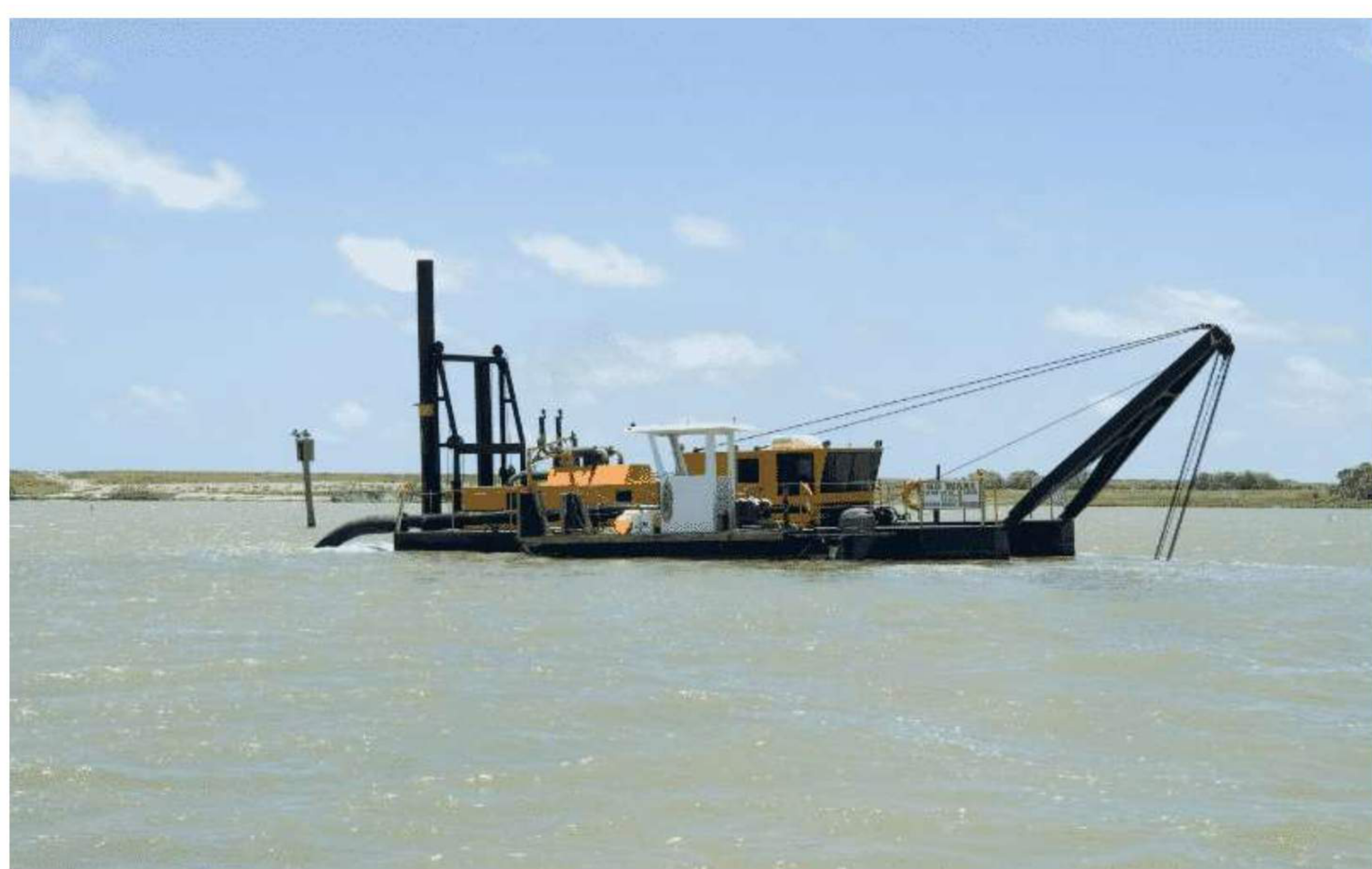
Dredging is an excavation activity usually carried out underwater, in shallow seas or freshwater areas, to gather up bottom sediments and widen channels. Dredgers are vessels with excavation tools used for removing sand and other deposits from the seabed, for purposes such as making shallow coastal areas navigational and for deep-sea mining. They are classified into two types: mechanical dredgers and hydraulic dredgers.
1.1.12 Size classes and canal limits
This group of terms is about the physical limits imposed by the world's canals and by port facilities, and it comes up constantly at orals.
| Class | Meaning |
|---|---|
| Panamax and New Panamax | Ships designed to travel through the Panama Canal |
| Suezmax | The largest ship that can pass through the Suez Canal |
| Capesize | Vessels which cannot pass through the canals of Panama and Suez, and so generally traverse the Capes of Good Hope and Horn |
| Handymax | Small cargo ships — often bulk carriers — of up to 60,000 tonnes deadweight, typically 150–200 m long, able to enter most port and harbour facilities |
Handymax vessels are among the most commonly used vessels in the global merchant fleet because they can gain easy entrance through most port and harbour facilities.
1.1.13 Chemical tanker types under the IBC Code
According to the IBC Code there are three types of chemical tanker, graded by the hazard of the cargo and therefore by the containment the ship must provide:
- ST1 — intended to transport the most dangerous products, requiring maximum preventive measures to avoid escape of cargo. A type 1 ship must survive the most severe standard of damage stability, and its cargo tanks must be located at the maximum prescribed distance on board from the shell plating.
- ST2 — intended to transport products requiring significant preventive measures.
- ST3 — intended to transport products requiring only a moderate degree of containment to increase survival capability in a damaged condition.
Tank capacity limitation
| Type | Limit |
|---|---|
| ST1 | Quantity of cargo required to be carried < 1,250 m³ in any one tank |
| ST2 | Quantity of cargo required to be carried < 3,000 m³ in any one tank |
| ST3 | No filling restriction |
Tank location
| Type | Required location |
|---|---|
| ST1 | From the side shell plating not less than B/5 or 11.5 m, whichever is less; from the moulded line of the bottom shell plating at the centreline not less than B/15 or 6 m, whichever is less; and nowhere less than 760 mm from the shell plating |
| ST2 | From the side shell plating not less than 760 mm; from the moulded line of the bottom shell plating at the centreline not less than B/15 or 6 m, whichever is less |
| ST3 | No requirement |
1.1.14 Crude carrier against product carrier
MARPOL 73/78 defines the two: a crude oil tanker is an oil tanker engaged in the trade of carrying crude oil; a product carrier is an oil tanker engaged in the trade of carrying oil other than crude oil.
The structural differences follow from that:
- The larger the ship, the heavier the structural members — increased scantlings.
- The crude oil tanker has a small number of large cargo tanks, while the product carrier has a large number of small tanks. Crude oil transported is for most of the time a single kind coming out of an oil well and needs little segregation; a product carrier must carry a number of different products out of the same refinery, which must be segregated.
- Comparing two ships of identical size, the product carrier is inherently stronger because of the many transverse and longitudinal bulkheads installed to subdivide the cargo area. The large cargo tanks of a crude oil carrier need additional strengthening by way of thicker bulkheads, deeper longitudinal and transverse girders, and closely spaced frames and stiffeners.
1.1.15 Product tanker against chemical tanker
The difference is all about cargo compatibility, and it shows up in the framing and the piping:
- An oil tanker has internal framing — the frames, or ribs, of the ship pass through the tank. This creates pockets where cargo can be trapped, but that is usually negligible when the vessel repeatedly loads and unloads the same type of cargo.
- A chemical tanker has external framing. Chemical tankers often change the type of cargo carried in a particular tank on each trip, so they must be able to clean the tank completely and remove any residue from the previous cargo.
- A chemical tanker carries far more piping along the deck. To ensure cargo separation, each tank has a dedicated pipe running from it to the cargo manifold, and each tank usually has its own pump. That is what allows a chemical tanker to carry multiple types of chemicals safely.
- An oil tanker usually has three connections at the manifold running to three pumps down in a pump room next to the engine room. Each pump is connected to multiple tanks to pump cargo to a facility or to another vessel.
1.2 Hull form
1.2.1 Camber
Camber, or round of beam — the transverse curvature of the deck from the centreline down to the sides. Camber is used on exposed decks to drive water to the sides of the ship. Other decks are often cambered. Most modern ships have decks which are flat transversely over the width of the hatch or centre tanks and slope down towards the side of the ship.
Camber is measured by the difference between the heights of the deck at side and centre. The camber amidships is frequently one fiftieth of the breadth of the ship.
It is the transverse upward curve of the upper deck, designed to enable the vessel to shed water overside easily. It is rarely called the belly of the deck; in America it is called the crown of the deck.
Purpose:
- To facilitate drainage of water.
- To increase the resistance to deflection under load.
- To avoid the humps and hollows that welding distortion would produce on a flat upper deck — those would delay complete drainage.
Standard camber is parabolic and approximately 1/50th of the breadth. Modern ships have "dog-leg" camber, where the deck is level across the deck between the hatches and then drops in a straight line to the deck at side.
1.2.2 Sheer
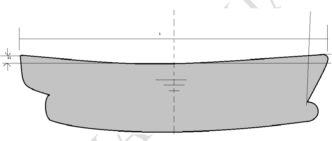
Sheer — the curvature of the deck in a fore-and-aft direction, rising from midships to a maximum at the ends. The sheer forward is usually twice that aft. Sheer on exposed decks makes a ship more seaworthy by raising the deck at the fore and after ends further from the water and by reducing the volume of water coming on deck.
It is measured between the deck height amidships and the particular point on the deck. The amount of sheer is measured vertically from a level line through the deck at midships to the deck at the two perpendiculars.
Purpose:
- To increase reserve buoyancy at the ends of the vessel.
- To counter the immersion of the ends that may occur during pitching — important particularly for smaller vessels.
- To increase the seaworthiness of the ship, since the amount of water coming in on deck is reduced.
Since the fore end is more susceptible to immersion than the aft end, standard sheer is a parabolic curve with sheer forward twice that of sheer aft. Modern ships have straight-line sheer, often in the fore body only, and in some cases only over the forward one-third of the ship's length. Very large ships achieve the minimum bow height without any need for sheer; conversely, very small vessels may have very large sheer forward and aft.
1.2.3 Rise of floor
Rise of floor — the bottom shell of a ship is sometimes sloped up from the keel to the bilge to facilitate drainage. This rise of floor is small, 150 mm being usual.
The same feature carries a second name: dead rise is the athwartship rise of the bottom from the keel to the bilge.
Defined in terms of the moulded line: the rise of the bottom shell plating line above the base plane line, measured at the line of moulded beam. At the amidships region the bottom of the ship is extended out to intersect the moulded breadth line; the height of that intersection above the keel is the rise of floor, or dead rise.
1.2.4 Bilge radius
Bilge radius — the radius of the arc connecting the side of the ship to the bottom at the midship portion of the ship.
1.2.5 Tumblehome
Tumblehome — in some ships the midship side shell in the region of the upper deck is curved slightly towards the centreline, reducing the width of the upper deck and decks above. Such tumblehome improves the appearance of the ship. Stated more generally, it is the slant inward from the vertical of a transverse section of a hull about the designed waterline.
1.2.6 Flare
Flare — the outward curvature of the shell at the forward end of the ship, or the spreading out of the hull form from the centre vertical plane, usually in the fore body above the waterline.
Purpose:
- It increases the reserve of buoyancy at the forward end, giving better seaworthiness when pitching.
- Water is dispersed away from the ship when lightly pitching.
- It creates a wider forecastle deck, giving more space for fitting machinery such as the windlass.
- It allows the anchor to be cleared up clear of the water, reducing hull damage by abrasion.
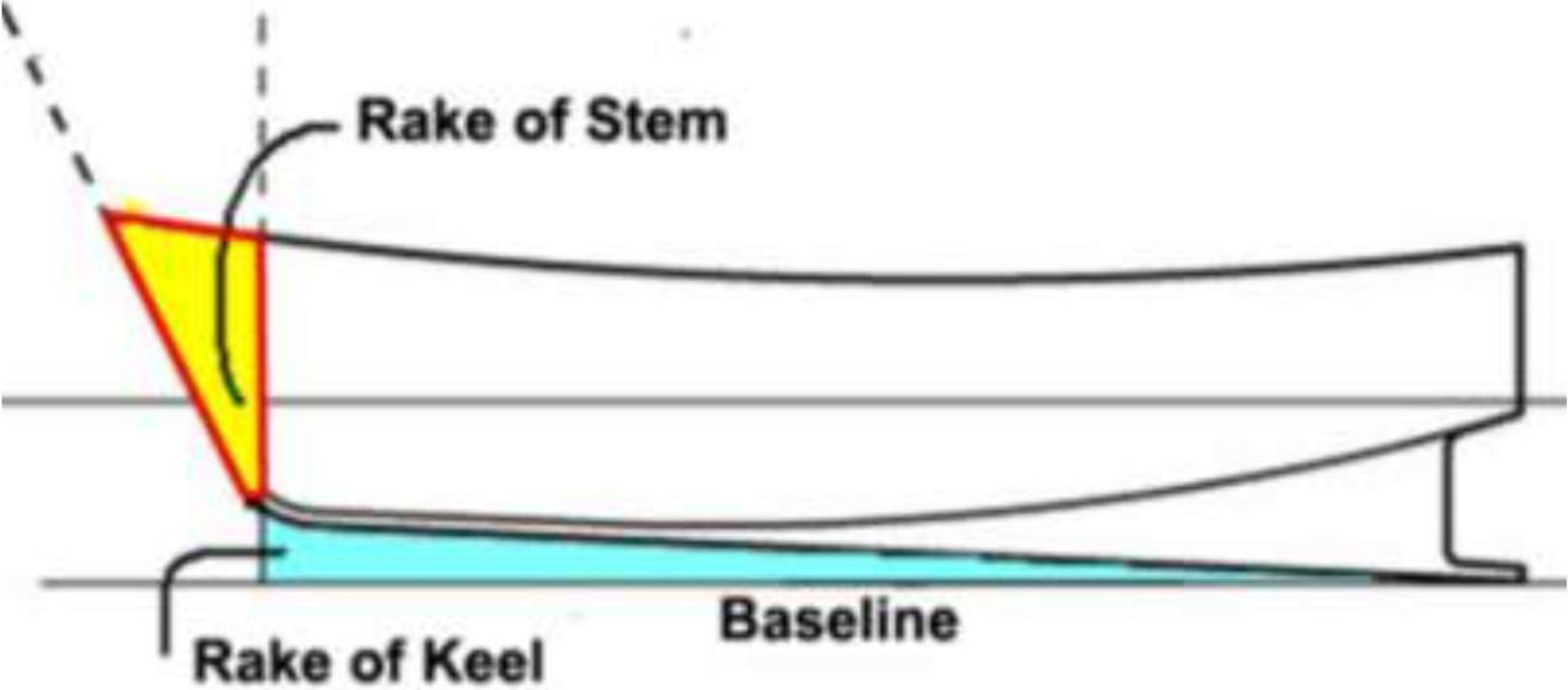
1.2.7 Stem rake and keel rake
Stem rake — the inclination of the stem line from the vertical.
Keel rake — the inclination of the keel line from the horizontal. Trawlers and tugs often have keels raked aft to give greater depth aft, where the propeller diameter is proportionately larger in this type of vessel. Small craft occasionally have forward rake of keel to bring propellers above the line of keel.
1.2.8 Scantlings
Scantlings — the dimensions and thickness of rolled sections, and the breadth and thickness of plates, which together compose the ship's structure or part of it.
1.3 Shell plating and strakes
1.3.1 Strake
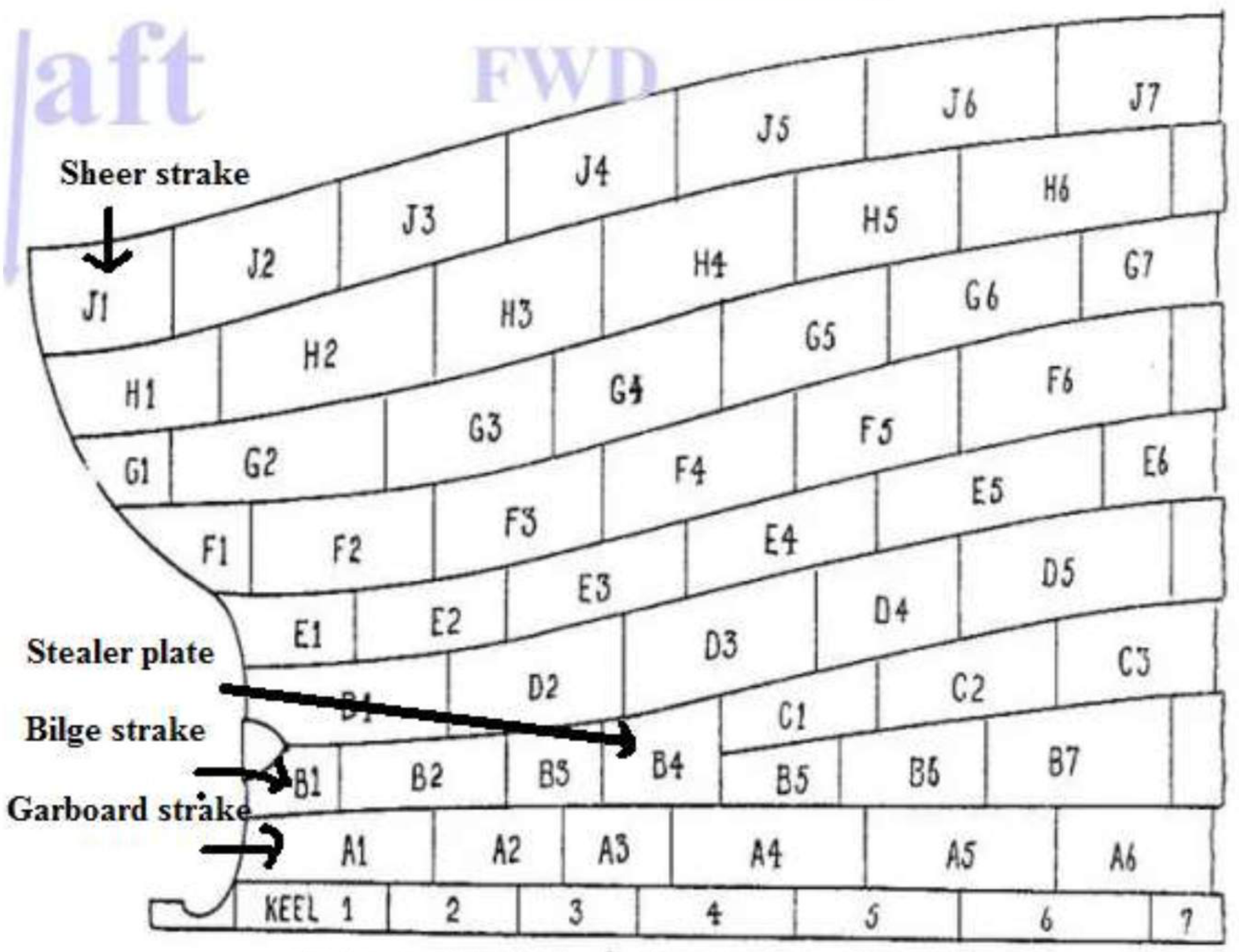
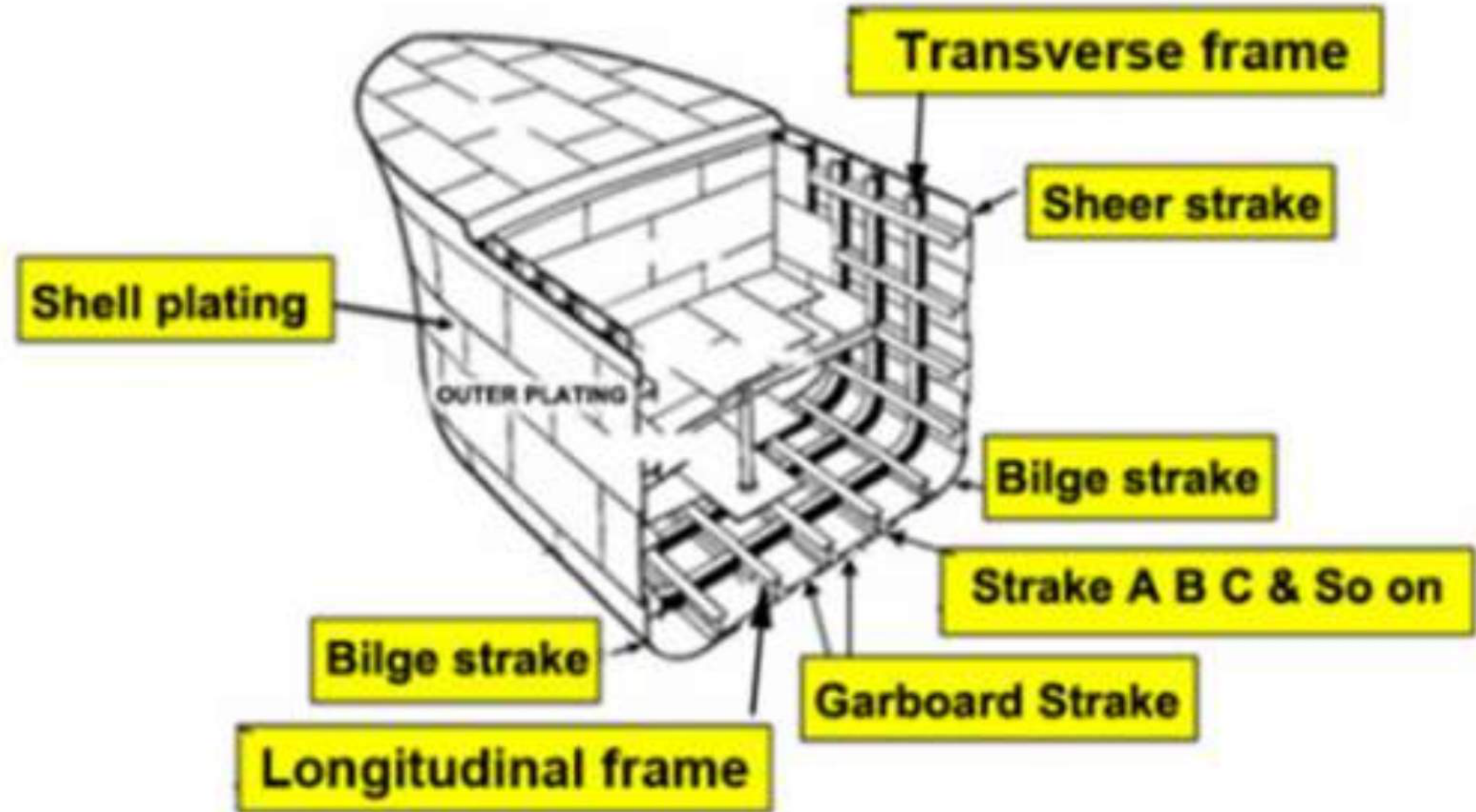
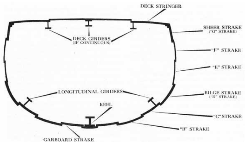
On a vessel's hull, a strake is a longitudinal course of plating which runs from the boat's stem post (at the bows) to the sternpost or transom (at the rear). The external hull of a ship consists of bottom shell, side shell and deck, which are formed by longitudinal strips of plating called strakes — a continuous range of plate forming the side of the vessel, or metal plate extending the ship's hull from stem to stern.
1.3.2 Bilge strake
The strake at the turn of the bilge is called the bilge strake.
1.3.3 Stealer plate
At the ends of a vessel, particularly at the bow or aft, the width of the strake decreases and it is often desirable to merge two strakes into one. This is done by a stealer plate — a single wide plate which replaces two narrow plates in adjacent strakes of a ship.
1.3.4 Garboard strake
The strake adjacent to the keel on each side of the ship is called the garboard strake — the strake of the bottom shell plating adjacent to the keel plate.
It is the first strake on each side of the keel strake. As in the bottom strakes the first strake from the keel is named the A-strake, the bottom A-strake is called the garboard strake.
1.3.5 Sheer strake
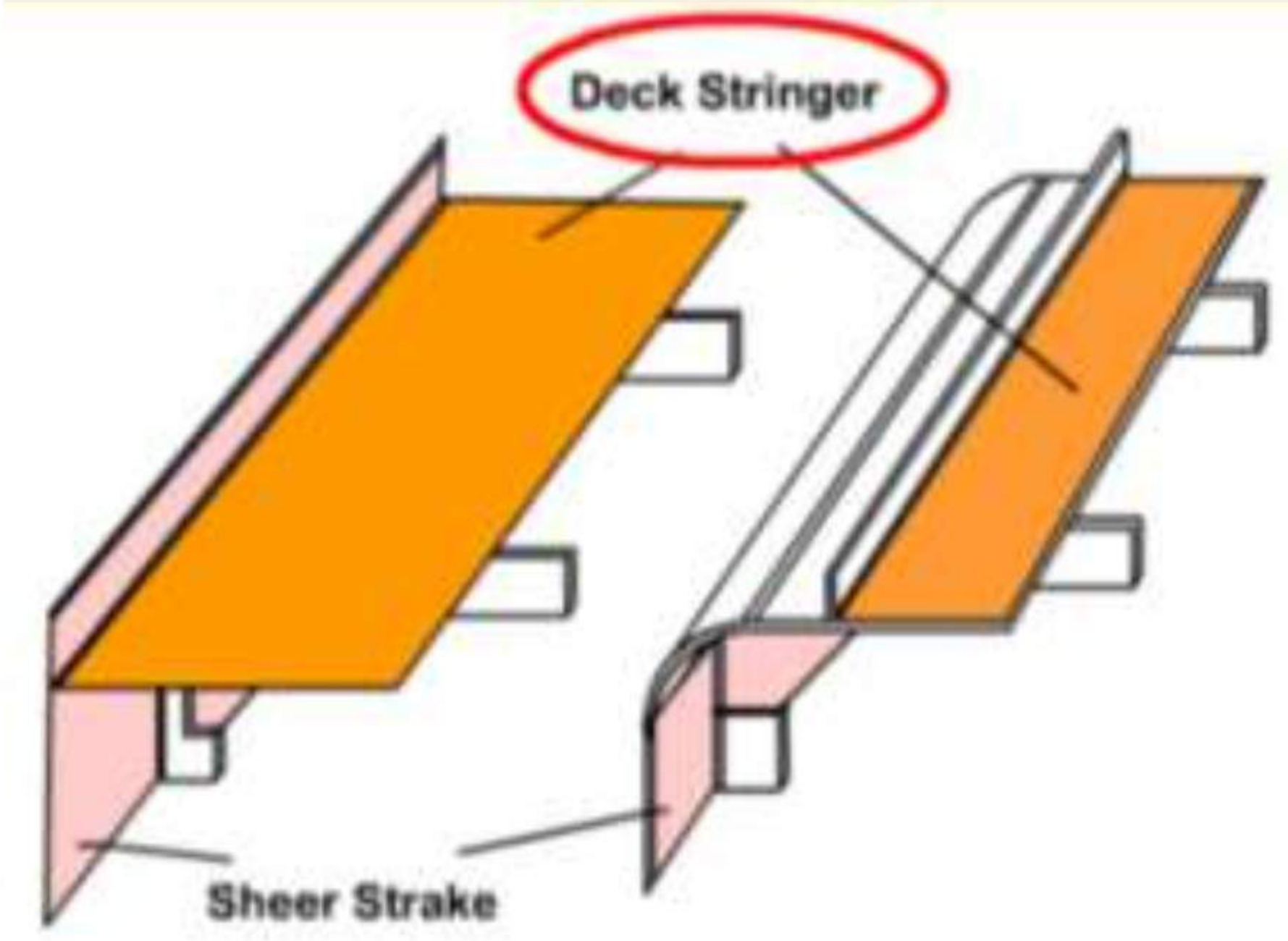
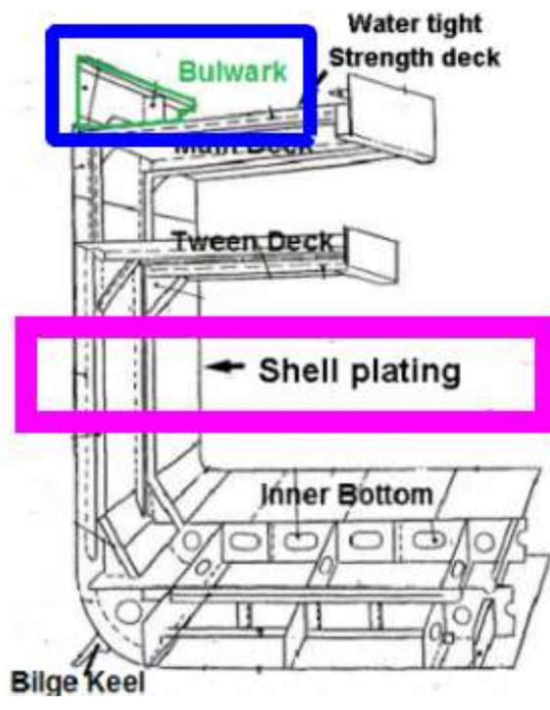
The sheer strake is the largest continuous strake at the top of the side of the vessel on the main deck — the uppermost strake of side plating, which meets the upper deck, and the course of the shell plating at strength-deck level. It is 10–20% thicker than the other side plating.
Its importance: when the vessel is bending under forces from tension to compression, the sheer strake is subjected to the maximum compressive and tensile stress, and so contributes to the strength of the hull. It is usually of higher thickness and strength than the other strakes because it can resist a lot of physical damage during the life of the ship.
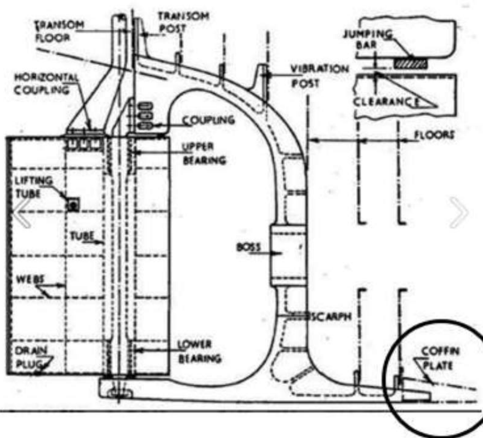
1.3.6 Docking plug
A docking plug is a brass screw fitted in the garboard strake of the shell plating at the bottom of each compartment, to drain the water which remains in the ballast tanks while the vessel is in dry dock.
1.3.7 Coffin plate
The coffin plate is used to connect the stern frame to the flat plate keel.
The stern frame is extended forward far enough — two or three frame spaces — to provide a good connection with a flat plate keel, and the aft-most plate of the keel, the coffin plate, is dished around the extension.
1.3.8 Shoe plate
The shoe plate is used to connect the stem to the flat plate keel. The forward end of the shoe plate is dished around the stem, whilst the after end is flattened to connect with the keel plate.
1.3.9 Oxter plates
Oxter plates are peculiarly curved plates, fitted where the stern frame meets the overhang of the stern.
1.3.10 Breast hook and tie
A breast hook is a triangular plate bracket joining structural members of the port and starboard sides at the stem.
A tie is the equivalent transverse connection within the structure — the term is listed alongside the breast hook in the same oral question.
1.3.11 Bitter end
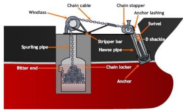
The bitter end is the inboard end of a ship's anchoring cable, which is secured in the chain locker by the clench pin.
1.3.12 Deck stringer plate
The deck stringer plate is the outboard strake of plating on any deck. It is shown at the deck edge, in way of the bulwark and the sheer strake.
1.4 Decks, bulwarks and boundaries
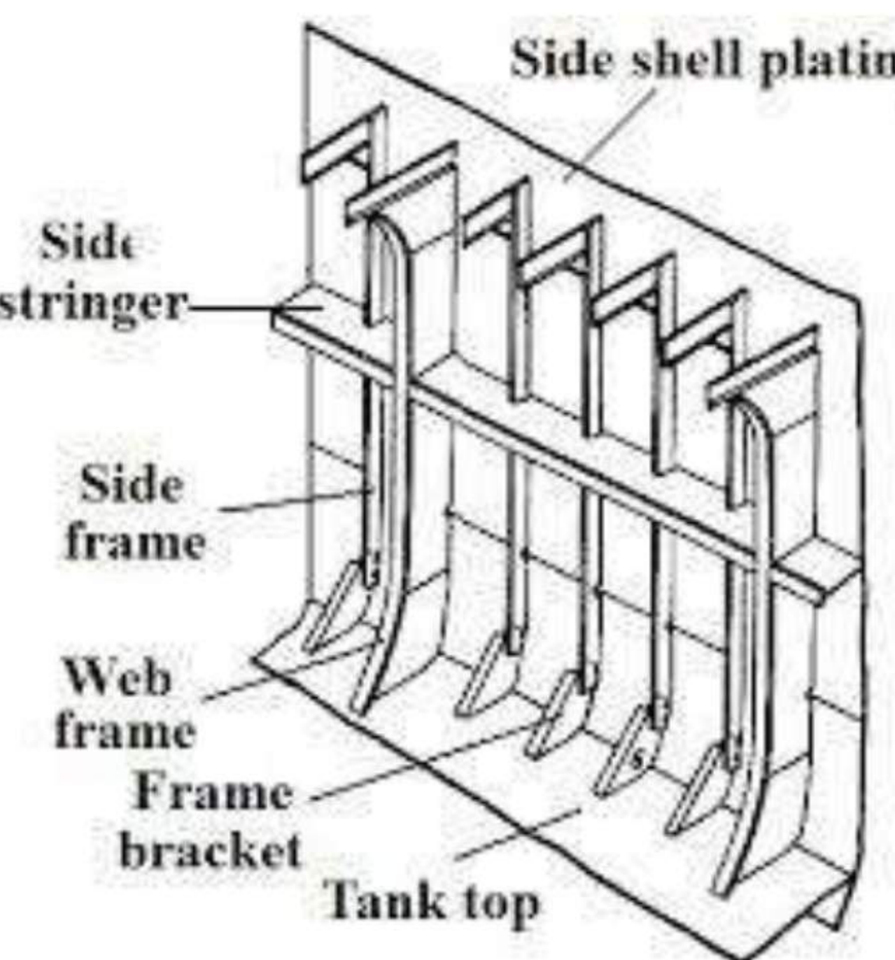
1.4.1 Stringer
The stringer is the stiffener used to strengthen the side surface of the ship; without stringers the hull shape does not form.
The term carries two senses, which is why it causes confusion:
- A horizontal stiffener fitted along the ship's side or along a longitudinal bulkhead, in order to provide strength and rigidity.
- A fore-and-aft girder running along the side of a ship at the shell, and also the outboard strake of plating on any deck.
1.4.2 Gunwale
The gunwale is the upper edge of a ship's side, where the sheer strake meets the deck plating — the top edge of the hull of a vessel, where it meets the deck. It is used as a valuable stiffener mounted inboard of the sheer strake on commercial vessels.
1.4.3 Bulwark
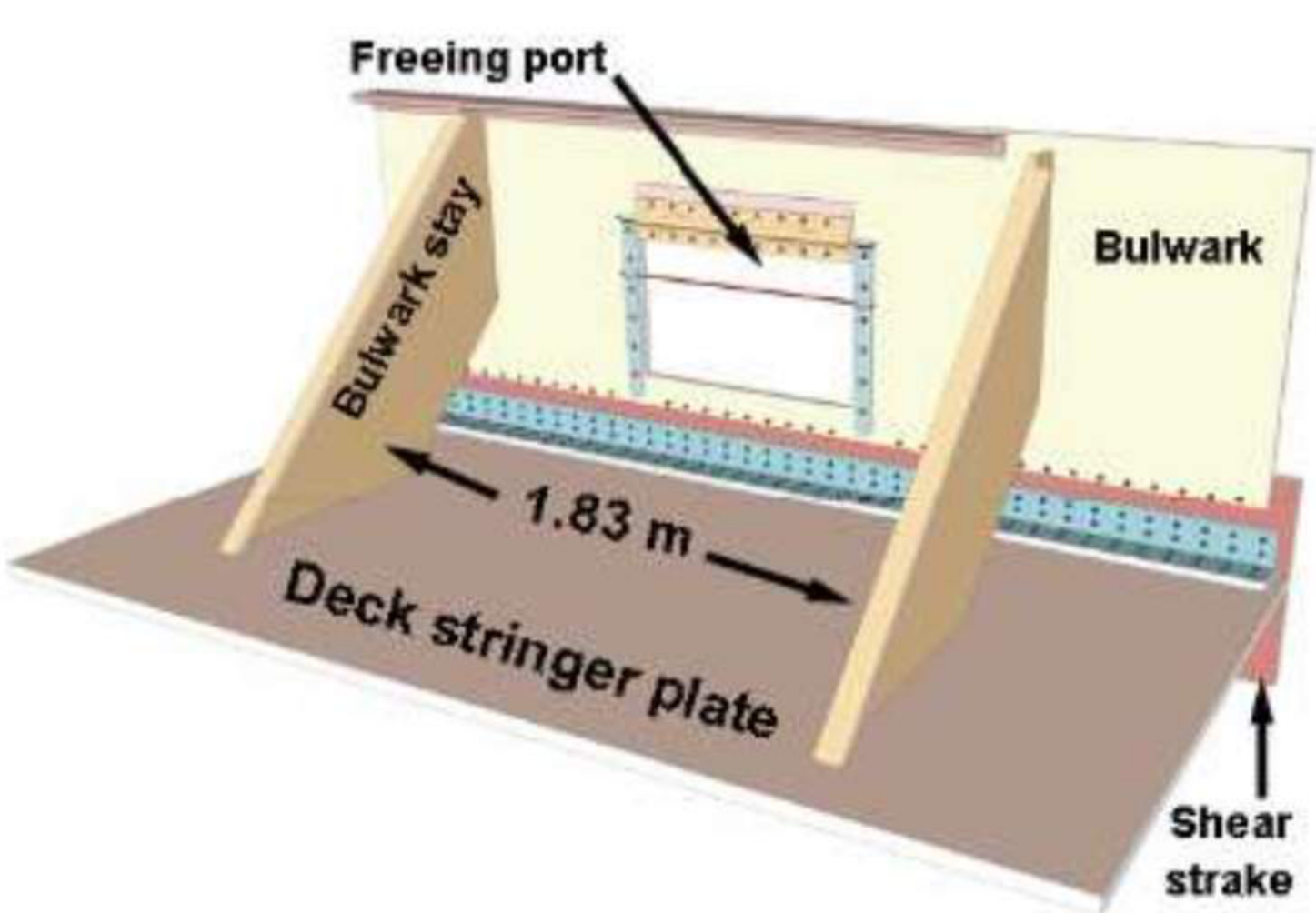
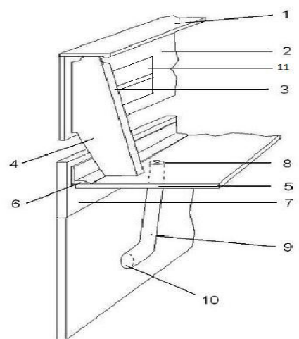
A bulwark is a solid wall that extends above the weather deck, or any other deck exposed to weather, fitted for the safety of the crew — a barrier fitted at the deck edge to protect passengers and crew and to avoid the loss of items overboard while the ship rolls excessively. It is at least 1 m in height; the spacing of stays does not exceed 1.2 m on the forecastle.
The bulwark stay is the bracket that supports it; the drawing marks a stay spacing of 1.83 m in the general arrangement.
1.4.4 Margin plate
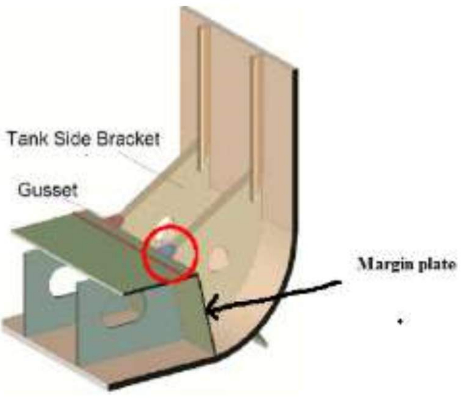
At the bilges the tank top may be either continued straight out to the shell by means of a tank margin plate, which is watertight and set at an angle of about 45° to the tank top, meeting the shell almost at right angles.
Structurally, the margin plate is the outboard strake of the inner bottom. When it is turned down at the bilge it forms the outboard boundary of the double bottom, connecting the inner bottom to the shell plating at the bilge.
1.4.5 Freeboard deck
The freeboard deck is the deck from which freeboard is measured — freeboard being the vertical distance from the load water line to the top of the freeboard deck. The term is asked for by name at the oral. The full definition of freeboard, its purpose and its effect on seaworthiness are in Part 1b, §1b.2.
1.4.6 Flush deck ship
A flush deck ship is a ship constructed with an upper deck extending throughout her entire length without a break or a superstructure such as forecastle, bridge or poop.
1.4.7 Margin line
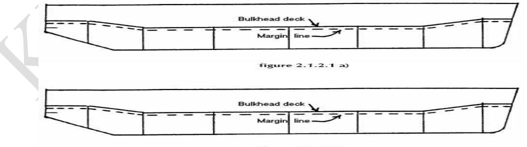
The margin line is a line drawn at least 76 mm below the upper surface of the bulkhead deck at side. It is an imaginary line drawn 76 mm below the uppermost continuous deck, and it denotes the limit up to which the ship can be flooded or loaded without sinking.
For a ship which has a continuous bulkhead deck, the margin line is taken as a line drawn not less than 76 mm below the upper surface of the bulkhead deck at side, except that where there is a variation in the thickness of the bulkhead deck at side, the upper surface of the deck should be taken at the least thickness of deck at side above the beam. If desired, the upper surface of the deck may be taken at the mean thickness of the deck at side above the beam as calculated for the whole length of the deck, provided that the thickness is no greater than the least thickness plus 50 mm.
It is the highest permissible location on the side of the ship of any damage water plane in the final condition of sinkage, trim and heel. If a ship is damaged, it is considered safe only if the margin line is not immersed. Once the waterline reaches the margin line at any point along the length of the ship, the ship is considered unsafe and evacuation becomes mandatory.
1.4.8 Carving note
A carving note is a form completed by the owner of the ship under construction. It gives details of tonnage, name, port of registry and so on.
1.4.9 Tonnage mark
The tonnage mark is a horizontal line 15 inches long and one inch wide. It must be designated by a welded bead or other permanent mark 15 inches long placed along the top edge of the tonnage mark. Above the tonnage mark is placed an inverted equilateral triangle, each side of which is 12 inches long and one inch wide, with its apex touching the upper edge of the centre of the tonnage mark.
Tonnage marks are entirely different from load lines and must not be used to indicate drafts or for any other purpose. Until the water is below the tonnage mark, a modified tonnage applies to the ship. The centre of the point where the triangle tip touches the tonnage line is situated 540 mm forward of the load line disc; for ships that carry timber it is 1080 mm away.