
Midship Sections Compared by Type of Ship
The same structural vocabulary arranged differently because the cargo is different — general cargo, bulk, tanker, LNG, container, Ro-Ro and passenger midships side by side.
Key Principles at a Glance 8 points
- Longitudinal strength depends on the section modulus of the midship section, so the midship region — one quarter of the length either side of midships — carries the maximum bending moment and constant scantlings.
- The general cargo midship is single skin with a tween deck and a half-width hatch, and its double bottom is worked as a tank for ballast and for trimming the ship.
- A dry bulk carrier adds wing tanks sloping to the hold sides so that cargo self-trims, and the bracket connecting them is the detail that fails in service.
- An OBO carrier raises the tank top above the normal height; the reason is stability, because a high tank top lowers the KG of a dense ore cargo carried in a narrow hold.
- A tanker is assigned less freeboard than a dry cargo ship of the same length because her subdivision and her small hatch openings give her greater reserve buoyancy after damage.
- LNG and LPG carriers carry their cargo in independent or membrane containment at cryogenic temperature, so the midship is built around the tank and its insulation rather than around the cargo.
- The container ship midship is a cellular box with a deep torsion box under the deck, because the whole strength case for a ship with a full-length hatch opening is torsion.
- The Ro-Ro midship is a stack of continuous decks with no hatch openings at all, so the strength case is transverse and the racking resistance has to come from the side structure.
11.1 General cargo and bulk
The same structural vocabulary as Parts 6 to 10, arranged differently because the cargo is different. Read Part 4, Longitudinal strength and the midship section, first — this is where section modulus is decided.
11.1.1 Why the midship section decides the ship
The longitudinal strength of the hull girder depends on the section modulus of the midship section. The section modulus in turn depends on the scantlings and layout of the structural members in the midship region.
Three consequences follow, and they govern everything in this part:
- The midship region extends one-fourth of the ship's length forward and aft of midships. The maximum longitudinal bending moment is experienced by the hull girder within this zone.
- Over this midship region the scantlings of the structural members are kept the same.
- The midship section depicts the structural layout depending on the type of cargo the ship is going to carry. Different types of ships therefore have different midship sections.
These plans are statutory structural plans, approved by the classification society concerned. That is why the same member — a side frame, a stringer, a girder — appears in every section in this part but is spaced, sized and framed differently in each: the cargo decides the opening, the opening decides the section, and the section decides the strength.
11.1.2 General cargo carrier — the go-anywhere ship
These ships are often referred to as go-anywhere type ships. They can carry any type of packaged cargo of varying dimensions — in drums, bags, bundles, bales or individual pieces.
The operational point comes before the structural one:
These vessels are always equipped with cargo handling gear of their own, generally in the form of derricks or deck cranes. Thereby these vessels do not depend on the port facility as far as cargo loading and unloading is concerned. Hence, irrespective of the cargo handling facility available in a given port, these vessels can load and unload cargo in any port, provided the water draft available is adequate for the ship.
Capacity and speed. Capacity is always on the lower side, generally not exceeding about 12,000 tonnes; speed is also on the lower side, about 10–12 knots.
The economics behind those low numbers is worth stating, because it explains why the type has barely changed:
- Each item of cargo is handled individually, so loading and unloading is lengthy — port time goes beyond three weeks, 21–30 days or even more.
- Fuel consumption rises exponentially with speed, so higher speed costs substantially more.
- Higher speed only pays if the days saved at sea are comparable to the port time. With three weeks in port, saving a few days' sailing by burning more fuel is not economically viable.
So the general cargo carrier stays small and slow: the longer she waits in port the more she spends, and she only earns when she sails with cargo.
11.1.3 General cargo structure — single skin, tween deck, half-width hatch
Structural features. These vessels are of single skin type with double bottom and generally have at least one tween deck, provided for facilitating cargo segregation and stowage. Decks and double bottom are longitudinally stiffened, whereas the side shells are transversely stiffened.
Hatches and holds. The engine room is generally in the semi-aft position — one cargo hold aft of the engine room, the rest forward. Each hold has one hatch opening with a hatch width somewhat less than half the deck width. Multiple hatch openings per hold improve loading and unloading but add to the production cost of the ship.
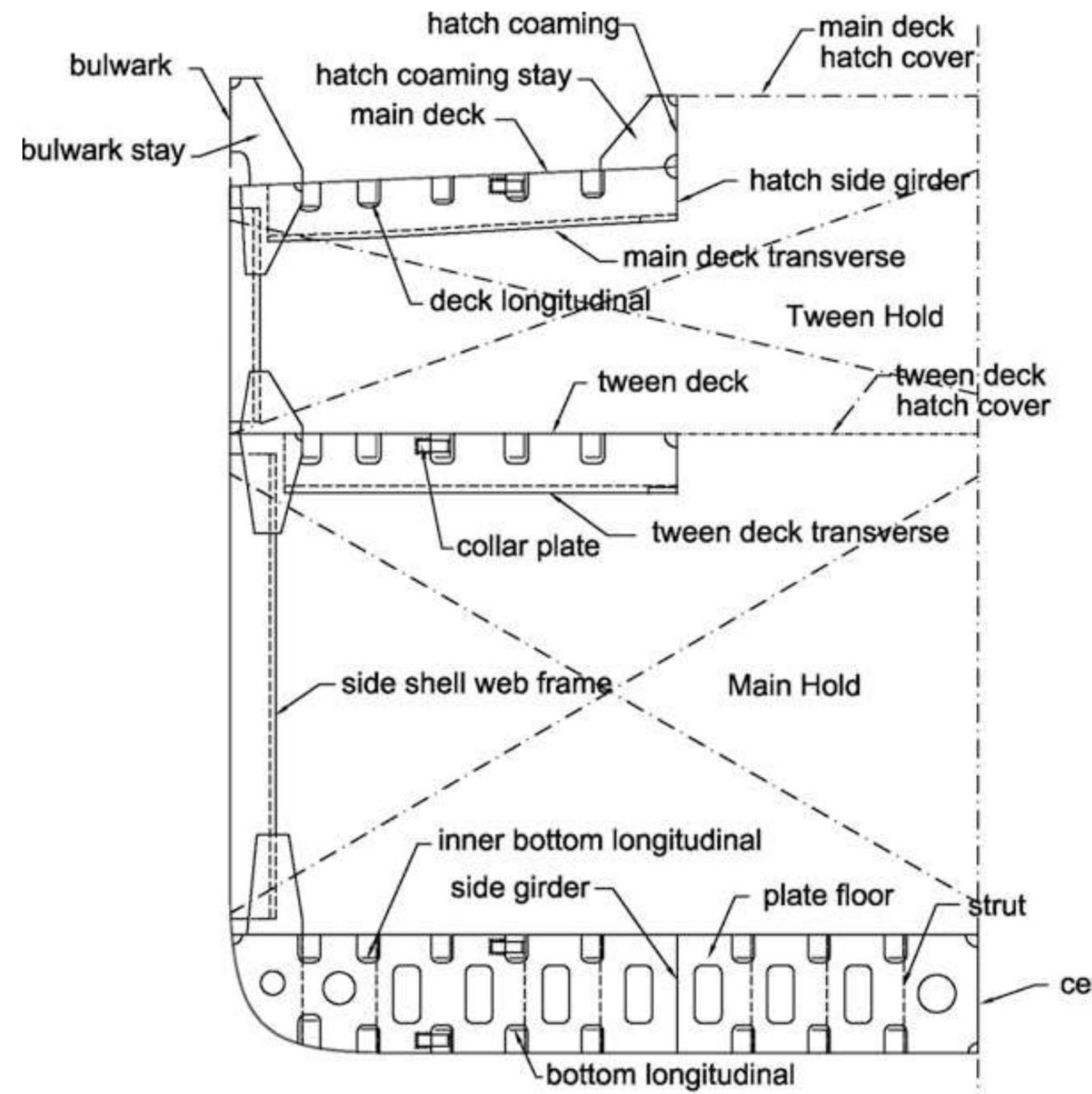
The members to name in the drawing are the bulwark and bulwark stay at the top, the hatch coaming with its stay and hatch cover, the main deck with its longitudinal and transverse, the tween deck with its cover and transverse, the collar plate where the deck meets the frame, the side shell web frame, the inner bottom longitudinal, the side girder, the plate floor with strut, the centre girder and the bottom longitudinal.
11.1.4 Dry bulk carrier — wing tanks and the bracket that fails
Introduction. These vessels carry dry cargo in bulk — grains, pulses, sugar and the like. Vessels carrying ore, coal or other high-density bulk cargo are referred to as ore carriers, coal carriers or combination carriers. For loading they depend on port facilities — automated, through conveyors and hoppers — but they are fitted with deck cranes for unloading; low-density cargo like grain is unloaded by pumping, coal and iron ore by grab buckets.
Structural features. These are single decker vessels with top and bottom wing tanks with sloping bulkheads. The wing tanks are kept empty or used for ballasting. In some bulk carriers the sloping bulkhead of the top wing tank is hinged to the side shell structure: lowered, it behaves like a lower deck and the space can carry general cargo.
The framing split is deliberate:
| Member | Framing |
|---|---|
| Wing tanks and double bottom | Longitudinally stiffened |
| Side shell in the hold region | Transversely stiffened — to avoid retention of cargo on the webs of longitudinal stiffeners after unloading |
The known failure. Structural failures are observed where the side shell frames connect to the sloping bulkhead of the bottom wing tank. The corrosion rate there is comparatively higher because dust and dirt from the bulk cargo accumulate along the welded joint; under normal service loads, and with gradual wastage of metal through corrosion, complete detachment of the bracket takes place.
That is the survey point for a bulk carrier: the bracket at the foot of the hold frame, where cargo dirt, a weld and a stress concentration meet.
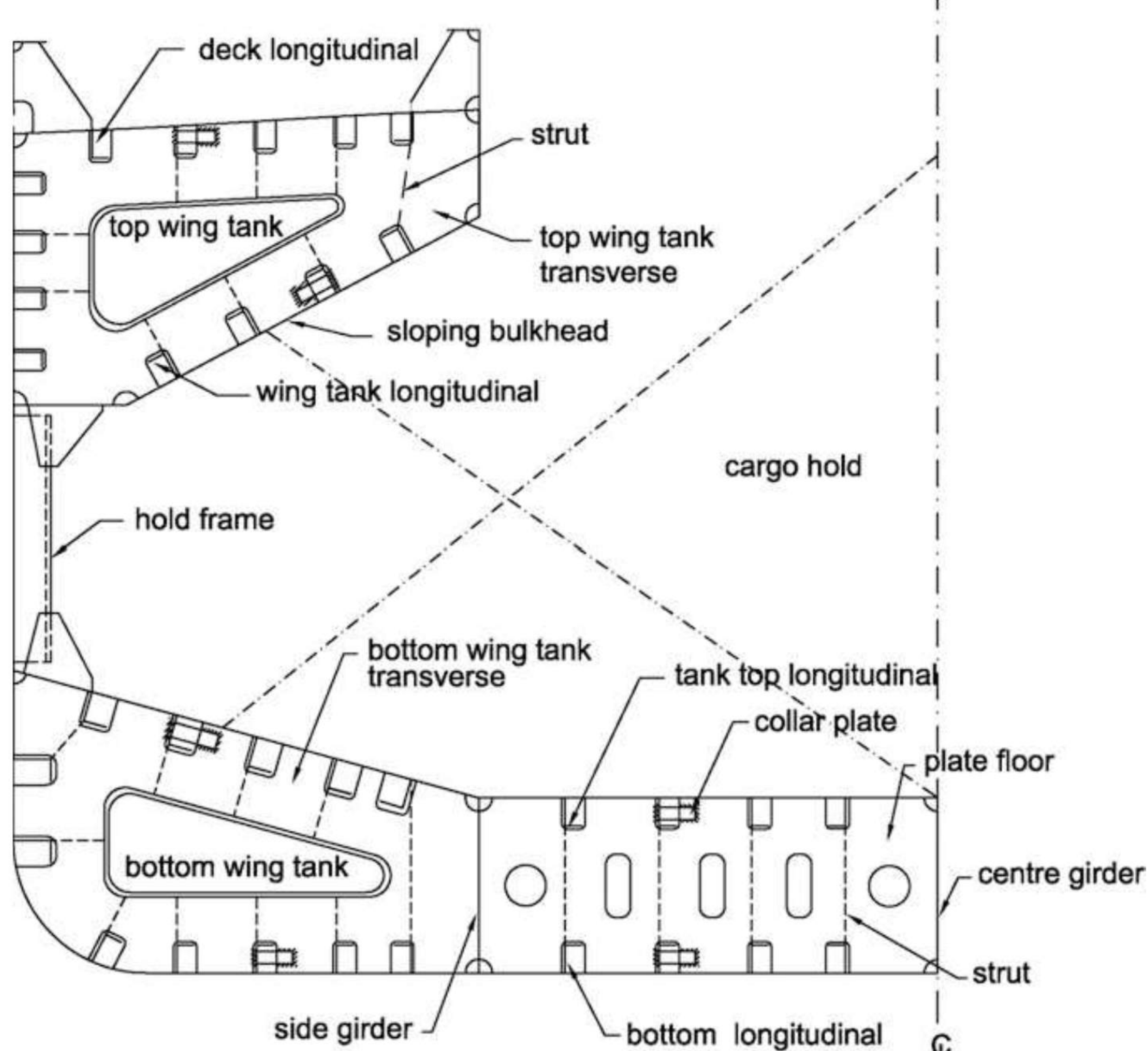
Capacity and speed. Bulk carriers range from about 20,000 t to about 80,000 t. Loading and unloading are well mechanised, so port time is much less than a general cargo ship's, and higher capacity is therefore economic. Preferred speed is 15–20 knots — higher than a general cargo carrier's, because fast cargo handling means the extra trips per annum a higher speed buys are actually worth having.
11.1.5 OBO carrier — raising the tank top to tame the GM
The problem. The double bottom height of a high-density bulk cargo (ore/coal) carrier is substantially higher than a normal bulk (grain/pulses/sugar) carrier's. This is done to raise the vertical centre of gravity of the vessel in the full load condition — and the reason is what happens without it:
- Ore is 7–8 times as dense as grain cargo. A full deadweight of it occupies a small part of the hold, so a large part of the hold remains empty.
- The empty space lets the cargo shift when the ship rolls, damaging the side shell and listing the vessel to one side. The permanent heel destroys course-keeping stability: the ship needs continuous rudder angle to hold course, and part of the power is consumed forcing her back into her path.
- The VCG sits very low, so the metacentric height is substantially high — the ship is stiff, with a very high righting moment. Heeled by a wave or a gust, she snaps back so fast she rolls violently to the other side: a severe rolling motion.
The answer — the combination carrier. The hold volume is made smaller by raising the tank top and providing inner side shells. Raising the tank top raises the VCG, so GM falls and the vessel becomes tender; the inner side shells shrink the hold so it stays full and the cargo cannot shift. The space created by the inner side shells carries liquid cargo on the return voyage.
Tank top strengthening. The tank top plating in way of the cargo hold needs additional strengthening on ore carriers: heavy cargo drops from a height onto it during loading, and the grab bucket strikes it while emptying the hold during unloading. Both cause severe loading, erosion and possible deformation.
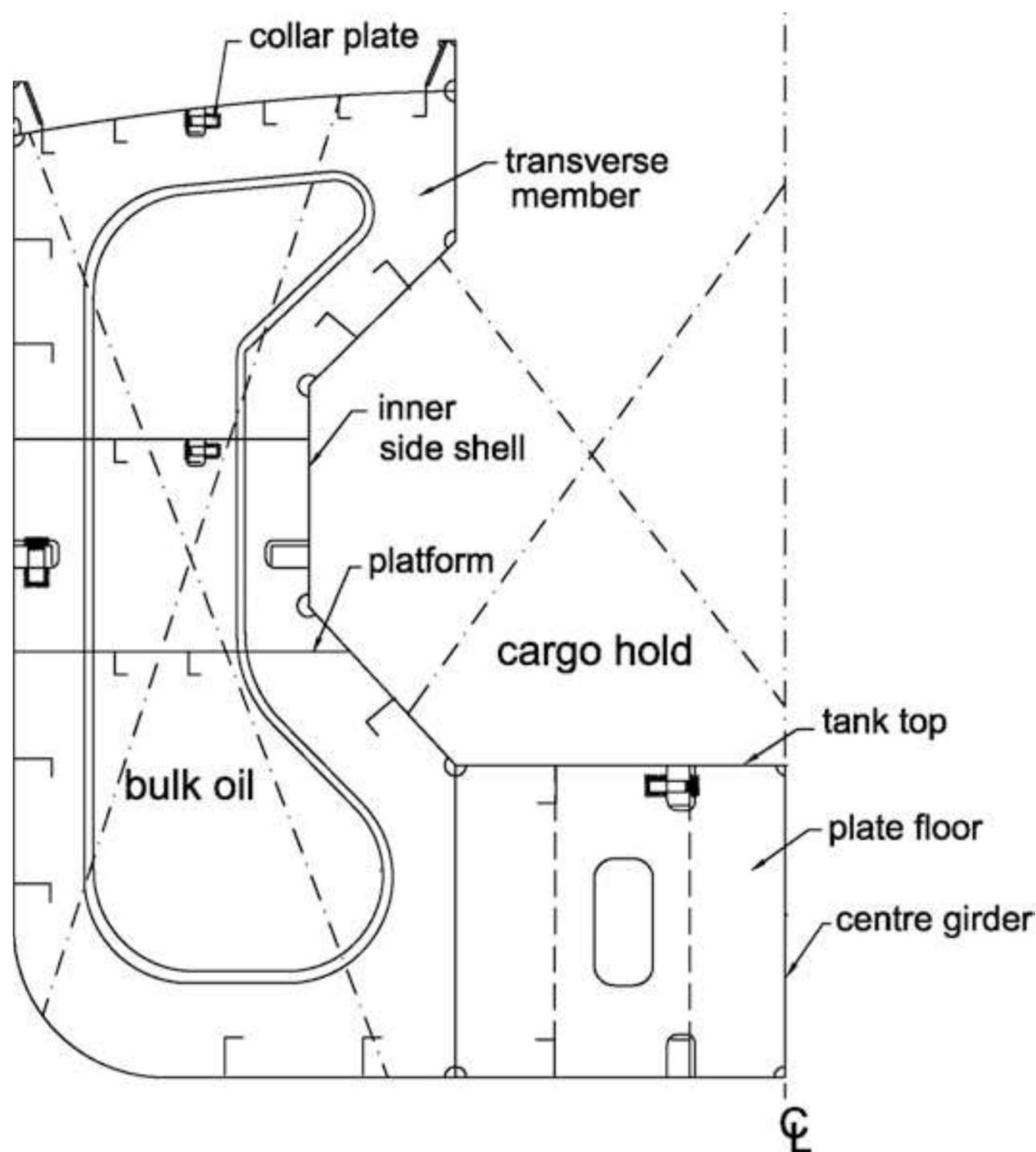
Hatches and holds. The engine room is fully aft — all holds forward of it. Each hold has a hatch opening of about half the main-deck width at midships, with a watertight hatch cover. Deck cranes stand between the holds on the main deck, supported by the transverse subdivision bulkheads. In loading and unloading, alternate-hold loading must be avoided: empty and full holds side by side develop severe shearing force in the structure around the full hold.
11.1.6 Bulk carrier against oil tanker — the structural differences
Taken as a set, in the form the oral wants it:
| Feature | Bulk carrier | Oil tanker |
|---|---|---|
| Cargo hold openings | Large cargo hold openings | Small opening to enter the cargo hold |
| Cargo operation | By ship/shore gear, sling or conveyor | By pipeline |
| Appearance | Pipelines all round the deck | Comparatively fewer pipelines |
| Cargo gear, where fitted | Cranes, derricks | Usually one or two midship cranes |
| Extra machinery | None required | Inert gas, separate pump room |
| Hull construction | Double hull not compulsory | Double hull compulsory |
| Catwalks | Fitted athwartship | Fitted longitudinally |
| Cargo tank cleaning | Easy | Comparatively difficult, COW washing |
| Entering the hold | No company permission needed (risk assessment carried out) | Company permission mandatory (risk assessment carried out) |
The pattern in the table is one principle stated nine ways: the bulk carrier is an open, mechanically worked ship — big hatches, grabs, conveyors, walkways across — while the tanker is a closed, piped ship — small openings, pumps, longitudinal access, gas control. Every structural difference between them follows from whether the cargo is handled through a hatch or through a manifold.
11.1.7 Why the tanker is assigned less freeboard
Tankers are assigned a smaller freeboard than bulk carriers for six connected reasons:
- Tankers have much smaller deck openings on the main deck.
- Tankers have greater subdivision, by additional longitudinal and transverse bulkheads.
- Tankers normally carry lesser-density cargoes — greater buoyancy.
- Tankers have greater GM values.
- Tankers have more pumps to control ingress of water quickly after a bilging incident.
- Tankers have a permeability of about 5% — lower permeability means less ingress of water following a bilging incident.
Note on the list. One account gives the first four reasons; another gives the same four with two more — the pumps and the 5% permeability. The six together are the answer to give.
Each reason is a different way of saying the tanker survives flooding better: less water gets in (small openings, low permeability), what gets in is contained (subdivision, pumps), and the ship that remains is more stable and more buoyant (GM, low-density cargo).
11.2 Liquid and gas carriers
11.2.1 Liquid bulk carriers as a family
Liquid cargo is carried in bulk either at room temperature and ambient pressure or at cryogenic temperature and high pressure. The family is:
- LNG/LPG carriers
- Crude oil tankers
- Product carriers and chemical tankers
Structural features, common to all of them. They are all single decker vessels; liquid cargo is carried in the cargo hold directly. All have double bottom and a completely closed main deck — except the LNG/LPG carrier. The longitudinal framing system is adopted throughout. Besides the watertight subdivision bulkheads, vessels have one or more longitudinal bulkheads according to size, provided to reduce the free surface effect of the liquids in the holds.
Crude carriers are very high capacity, exceeding 300–400 m in length; product carriers are around 220 m, chemical tankers around 120 m.
Why their strength is inherently good. There is no hatch opening, so the hull is a perfect closed-section structure; the longitudinal framing system adds to the longitudinal strength of the hull girder. Crude carriers are full-form ships with block coefficient 0.8 and above; product and chemical tankers are of fine form.
Double wall construction. Oil spillage from crude tanker disasters caused severe pollution of the ecosystem and coastal marine life, and regulation followed: double wall construction is mandatory for all seagoing crude carriers — a second wall of defence if the outer shell is damaged, preventing spillage. The double wall further contributes to the longitudinal strength, and the same logic applies to product and chemical tankers: all are of double wall construction.
11.2.2 Crude, product, chemical — sizes, speeds and holds
| Type | Size | Note |
|---|---|---|
| Crude carriers (VLCC/ULCC) | Up to 500,000 t or even more | Very high-volume crude import/export trade |
| Product carriers | 30,000–50,000 t | Different holds assigned to different products — edible oils and the like — each with its own pumping system |
| Chemical tankers | 2,000–10,000 t (a typical chemical tanker, Alcedo, 2,800 t) | Acids, alkalis and similar parcels |
| Gas carriers | 75,000–138,000 m³ of gas | Specialised containment, about one-third of the container above deck level |
Service speed for all of them is 16–21 knots — operable at the higher end because cargo handling is very fast (pumped, through inlet and outlet manifolds to each hold, with no hatch opening at all), so higher speed buys more round trips per annum.
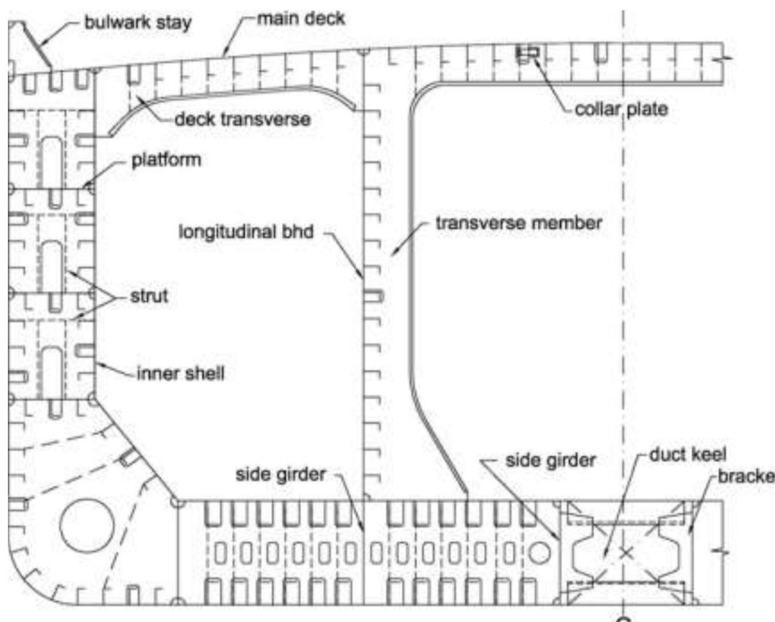
11.2.3 Tanker transverse cross-section — how the cargo tanks are strengthened
The drawing is the midship section of a double hull tanker. The right half shows an ordinary frame, the left half a deep transverse web frame:
- Outer and inner hull plates are longitudinally framed. The centre tank carries cargo oil; the wing tanks (segregated ballast tanks) carry seawater ballast and are epoxy-coated against corrosion.
- The longitudinal stiffeners on the wing tank longitudinal bulkhead are placed towards the wing tank, not the centre cargo tank — so that oil cannot accumulate on them.
- The double bottom spaces also carry water ballast, and the stiffeners on the inner bottom plating are always towards the double bottom space.
- A deep transverse web frame is fitted at every three to four frame spaces for transverse strength. The longitudinal stiffeners are welded to these web frames, and stringers on the transverse webs strengthen them further.
The stiffener-placement rule is the detail to carry: every stiffener in a tanker is put on the water side of its plate — wing-tank side of the longitudinal bulkhead, double-bottom side of the inner bottom — so that no stiffener ever stands inside an oil space collecting cargo.
11.2.4 Tank insulation on refrigerated cargo tanks
Thermal insulation is fitted to refrigerated cargo tanks for two reasons:
- To minimise heat flow into the cargo tanks, thus reducing boil-off.
- To protect the tanker structure around the cargo tanks from the effects of low temperature.
Insulation materials for gas carriers must possess five characteristics:
| Requirement | Why it matters |
|---|---|
| Low thermal conductivity | The insulating duty itself |
| Ability to bear loads | The cargo weight bears on it |
| Ability to withstand mechanical damage | Loading, sloshing and handling |
| Light weight | Deadweight is earning capacity |
| Unaffected by cargo liquid or vapour | The cargo must not degrade it |
11.2.5 LNG/LPG carriers — the cryogenic midship
Cargoes like liquefied natural gas and liquefied petroleum gas are carried under cryogenic conditions in extremely sophisticated vessels with containment systems that retain the cargo temperature. The cargo is of extremely low density, so much of the hull remains out of water, exposed to the atmosphere. In liquefied gas carriers the cargo is kept under positive pressure so air cannot enter the tanks.
Gas is always carried liquefied, and by its physical and chemical properties either under pressure above atmospheric, at temperatures below ambient, or both. The classification is:
- Fully pressurised
- Semi-pressurised and refrigerated
- Fully refrigerated
- Natural gas (methane, ethane): LNG ships carry at −161 °C at ambient pressure
- Petroleum gas (propane, butane): LPG ships carry at −42 °C, often under pressure
In LNG/LPG carriers the cargo sits in specialised containers with appropriate containment systems, the whole assembly placed in the holds with about one-third of the container outside the deck level. That one-third above deck is the visible signature of the type — and the reason these are the one liquid-bulk exception to the closed-deck rule of §11.2.1.
11.3 Container, Ro-Ro and passenger
11.3.1 Container ship — the standardised unit
The whole concept came into being to reduce port time. In a general cargo ship every item is individually handled and loading takes weeks; pack the cargo into standardised containers and each unit is handled as one standardised unit — containerisation raises the efficiency of cargo transportation.
Sizes and capacity. The standard lengths are 20-foot and 40-foot; the 20-foot box is the Twenty-foot Equivalent Unit (TEU), so one 40-foot container equals 2 TEU. The largest ships are about 400 m long and 55 m wide, powered by engines of about 2,300 tonnes with 130-tonne propellers, twenty-one storeys between bridge and engine room, typically 11,000 TEU and manned by just 13–14 people.
Speed is high — 20–25 knots — for the same reason as the tanker's: fast cargo handling means the time saved at sea is not swallowed in port.
11.3.2 Box girder midship — the answer for smaller container ships
The fundamental distinct feature of the container ship is its extremely wide hatch opening — a typical open-section structure. As capacity and length overall grew, the vessel became more vulnerable to longitudinal and torsional loading.
For smaller vessels adequate torsional strength was achieved with the box girder arrangement:
- The longitudinal framing system is adopted in the box girder as well as in the double bottom.
- The side shell is transversely framed — giving the necessary transverse strength and supporting the box girder arrangement.
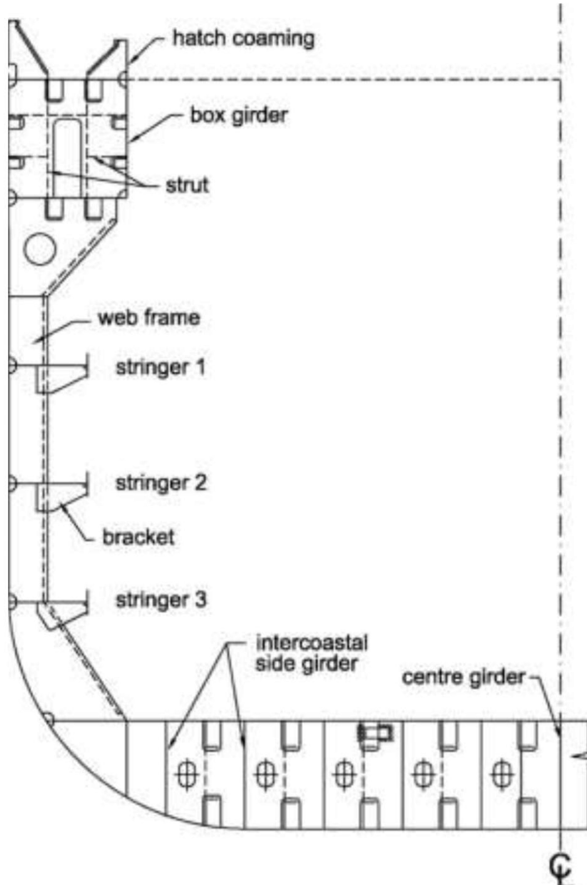
The hatch covers are necessarily of very long span because of the wide opening, and since containers are stacked over the covers they must be designed to withstand those loads.
11.3.3 Cellular midship — the answer for larger container ships
As vessel size increases the box girder becomes inadequate. For the required strength against torsion and longitudinal bending, cellular construction is adopted: in effect the box girder is extended down to the tank top plating, giving the cellular nature of the structure.
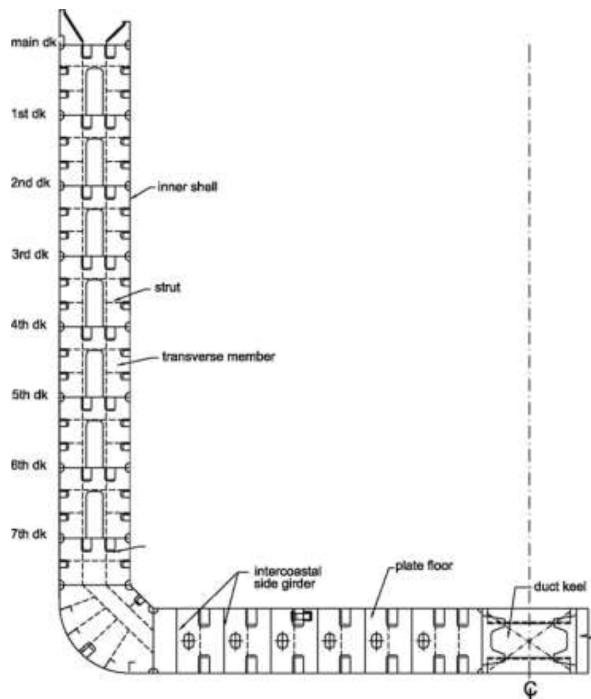
The prime feature remains the near open-deck construction — the very wide hatch opening through which containers are lowered vertically into the hold, one on top of the other, and unloaded the same way.
11.3.4 Torsion box — drawn, located, and why it matters
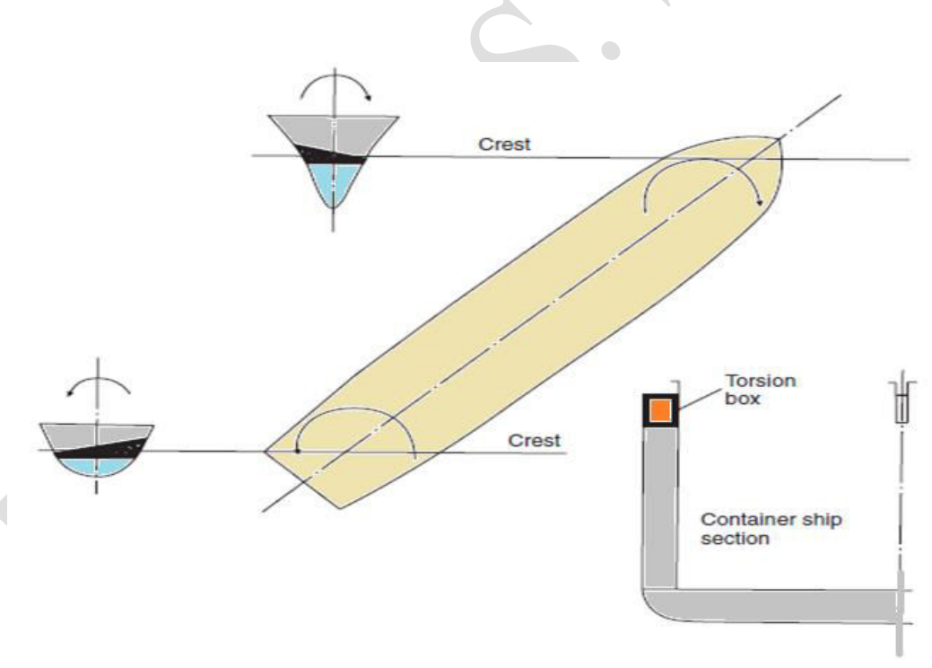
Location. It runs from the collision bulkhead to the aft peak bulkhead, on both the port and starboard sides.
What it prevents. Torsional bending from the torsional moment the dynamic movement of the waves puts on the ship, and the racking effect caused by the shear stress on the vessel.
Why the tanker and the bulk carrier do without it:
- The oil tanker has many transverse bulkheads acting as the main stiffening member against racking and twisting, together with the uppermost continuous deck, which has few hatch openings compared with a dry cargo ship. It needs no additional stiffening member like the torsion box.
- The bulk carrier has small hatch openings with sufficient deck space and deck stiffening members to counteract the twisting moment.
So the torsion box exists where the deck has been cut away for hatches and nowhere else: the tanker keeps its deck and its bulkheads, the bulk carrier keeps enough deck, and only the container ship — with its deck opened nearly full-breadth — must replace the lost strength with a dedicated member.
11.3.5 Racking — the theory behind the torsion box
What racking is. When a ship is rolling, the deck tends to move laterally relative to the bottom structure, and the shell on one side to move vertically relative to the other side. When a ship rolls there is a tendency for the ship to distort transversely the way a picture frame collapses. This is known as racking.
How it is resisted. It is reduced or prevented by the beam knee and tank side bracket connections together with the transverse bulkheads — the bulkheads having the greatest effect. Transverse bulkheads primarily resist the transverse deformation; the side frames' contribution is insignificant provided the transverse bulkheads are at their usual regular spacings.
Torsion, the companion load. When any body is subject to a twisting moment — torque — it is said to be in torsion. A ship heading obliquely (45°) to a wave is subjected to righting moments of opposite direction at its ends, twisting the hull and putting it in torsion. In most ships these torsional moments and stresses are negligible, but in ships with extremely wide and long deck openings they are significant — the larger container ship in particular, where at the topsides a heavy torsion box girder structure including the upper deck is provided to accommodate the torsional stresses.
The chain, in one line:
11.3.6 Ro-Ro ship — decks without hatches
These vessels carry wheeled cargo — passenger cars, trucks, trailers, railroad cars, heavy earth-moving vehicles — loaded and unloaded on their own wheels over ramps at the stern, bow or ship's side. Ro-Ro ferries carry passengers across short stretches of sea where no bridge is feasible: cars and restaurants on the car decks, drive in at one end, drive off at the other, and a very low port turnaround time.
Ventilation. Cargo-space ventilation is of additional importance: hundreds of vehicles run their own petrol or diesel engines to embark and disembark inside a closed space, and the exhaust, however small from each, accumulates to a significant level. The cargo ventilation system must be appropriately designed and completely segregated from every other ventilation system.
Structural features. The primary feature is the multi-deck vessel with unobstructed passage from the ramp end to the last hold's bulkhead. The earlier versions had no subdivision watertight bulkheads — anything to keep the vehicle run clear — so damage anywhere along the hold region flooded the entire vessel. Two losses forced the rule change: the Ro-Ro ferry Herald of Free Enterprise, capsized and sunk shortly after leaving Zeebrugge in March 1987, and the Ro-Ro ship Estonia, lost with more than 900 lives on 28 September 1994 when the bow door was torn off by heavy seas. Subdivision bulkheads are now mandatory; the transverse bulkheads carry power-operated sliding doors, and there must always be an inner door behind the bow door as a second line of defence.
With no hatch openings and multiple decks, adequate global structural strength is easily achieved. The decks and double bottom are longitudinally framed, the side shell transversely framed for better load distribution from the car decks to the hull girder. Car decks are strengthened for the local load of wheeled vehicles — and where extra-heavy vehicles are carried, strengthened accordingly.
Hatches and holds. There is no hatch opening for cargo. Access is through openings at the bow, stern or side shell in the fore or aft region, with ramps; subdivision bulkheads between holds have power-operated sliding doors for unobstructed vehicle movement and storage. Multiple car decks are connected by internal ramps at either end.
Capacity and speed. Types are Pure Car Carrier (PCC), Pure Car/Truck Carrier (PCTC) and Large Car and Truck Carrier (LCTC); the PCTC generally loads through stern and side ramps together to handle thousands of vehicles faster. Ships are often fitted with height adjustable decks: a 6,500-unit vessel with 12 decks may have three decks taking cargo up to about 140 t, adjustable from 1.7 to 6.7 m deck height. Loading is very fast and port time low, so cruising speed is high — in excess of 20 knots.
11.3.7 Passenger ship midship section
The material treats the passenger ship as a ship type but gives no dedicated midship section drawing or structural arrangement for it — the midship chapter covers general cargo through Ro-Ro only.
11.3.8 Accommodation material and how it is welded to the deck
Accommodation material is aluminium alloy.
Joining it to a steel deck needs a transition, because aluminium cannot simply be welded to steel. A transition sheet of pure aluminium and mild steel, explosively bonded together, separates the aluminium and steel plates, and the weld nugget process joins sheet to plate — steel to steel on one side, aluminium to aluminium on the other, with the aluminium side welded first. Explosively bonded transition plates are how the aluminium deckhouse is joined to steel decks.
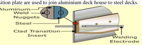
Newer welding techniques such as friction stir pot welding are being developed that will allow direct welding of steel to aluminium.