
Ship Stability: GM, Righting Levers and Free Surface
Why the ship comes back upright — the points, the lever, the GZ curve, and every way that curve fails, from a negative GM to pocketing in a slack tank.
Key Principles at a Glance 8 points
- The metacentre is where the vertical through the centre of buoyancy of an inclined ship cuts the centreline; it is not a fixed point, and below about 10 degrees of heel B, G and M may be treated as fixed.
- GM measures initial stability. Positive GM puts G below M and the ship returns upright; zero GM gives neutral stability; negative GM makes her unstable and she will loll.
- The GZ curve is the righting lever plotted against angle. Its maximum, the angle at which it vanishes, and the area beneath it are the three things the stability criteria actually test.
- A stiff ship has a large GM and a short, violent roll; a tender ship has a small GM and a long, slow one. Neither extreme is comfortable, and neither is safe at the limit.
- The free surface effect raises G whether the liquid is heavy or light and wherever the tank sits — the loss depends on the free surface inertia and the displacement, not on where the tank is.
- Dividing a tank reduces free surface loss roughly by the square of the number of divisions, which is why swash bulkheads and centreline divisions earn their steel.
- The inclining experiment finds the light ship KG by moving a known weight a known distance and measuring the resulting heel; the ship must be as near empty as possible for it to mean anything.
- Damage stability is judged against the margin line and a factor of subdivision, and the floodable length curve is what turns those into a permissible spacing of bulkheads.
3.1 The stability points and the lever
Why the ship comes back upright — the points, the lever, the curve, and the ways the curve fails.
3.1.1 Metacentre
The metacentre is the point where a vertical line through the centre of buoyancy of an inclined ship intersects the vertical line through the centre of gravity when the ship is floating in equilibrium. That is the definition for an inclined ship, and it is the one to give: the metacentre is not a fixed point. It exists because B has moved, and it is found by continuing the new vertical through B1 up to the ship's centreline — the point of intersection is M.
Two properties follow, and they are what the oral is actually testing:
- M is the centre of the circle on which B moves at small angles of heel.
- Below about 10° of heel, B, G and M may be treated as fixed for the purpose of finding GM. Above it, they may not, and the righting lever has to be read from the curve rather than calculated from GM.
3.1.2 Metacentric height
The metacentric height (GM) is the distance between the centre of gravity and the transverse metacentre M. It measures initial stability: the resistance of the ship to being heeled at small angles.
| Sign of GM | Position of G | Behaviour |
|---|---|---|
| Positive | G lies below M | The ship is stable; the moment created tends to return her upright |
| Zero | G coincides with M | Neutral stability — the ship rests at whatever angle she is put |
| Negative | G lies above M | The ship is unstable; the moment acts in the opposite direction and increases the angle of heel |
3.1.3 KG, KM and BM
| Term | Definition |
|---|---|
| KG | Height of the ship's centre of gravity above the keel. Found in section II(a) of the damage control book for each stated loading condition; for any other condition it must be calculated |
| KM | Height of the metacentre above the keel. Read from the draft diagram and functions-of-form curves in the same section of the book |
| GM | Metacentric height — the distance from G to M. A measure of the ship's initial stability |
| BM | Metacentric radius — the distance between the centre of buoyancy and the metacentre. It is the radius of the circle on which B moves at small angles of heel |
| GZ | Righting arm — the perpendicular distance between the line of action of the weight, through G, and the line of action of the buoyancy, through B1. It is the righting lever |
| RM | Righting moment — the ship's true tendency to resist inclination and return to equilibrium. It is the righting arm multiplied by the displacement |
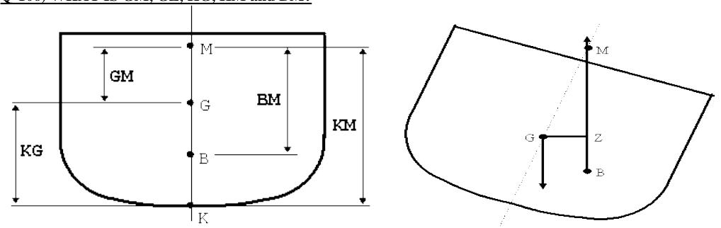
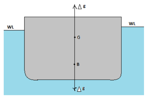
The three heights are connected by one relation, and it is the one that is asked for by name:
So the metacentric height is what is left of the metacentric height above the keel once the height of the centre of gravity has been taken out of it. K, G and M are all measured on the centreline for small angles of heel.
3.1.4 Righting moment, upright and inclined
In the upright position. The weight of the ship acts vertically down through the centre of gravity G, and the upthrust acts vertically up through the centre of buoyancy B. The weight is equal to the upthrust, and G and B lie on the same vertical line. The ship is in equilibrium.
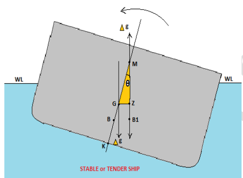
In the inclined condition. When the ship is inclined by an external force to an angle θ, the centre of gravity remains in the same position but the centre of buoyancy moves from B to B1. The buoyancy therefore acts upwards through B1 while the weight still acts downwards through G. The two verticals are now separated by the righting lever, and they create a moment of Δg × GZ which tends to return the ship to the upright.
Righting lever = GZ in metres, at the stated angle of heel
GZ × displacement at any angle is the righting moment at that angle. Expressed in tonnes and metres, the righting moment in tonne-metres is the righting lever in metres multiplied by the displacement in tonnes.
When G is below M the moment rights the ship and she is stable. When G lies above M the moment acts in the opposite direction, increasing the angle of heel: the vessel is unstable and will not return to the upright, and the metacentric height is regarded as negative.
3.1.5 The shift of G — GG1 and GG2
Any weight moved or added on board moves G, and every stability calculation on a real ship is built on that fact. Two cases are used constantly.
Weight moved within the ship — GG1. A weight already on board is shifted. G moves parallel to and in the same direction as the shift of that weight, and the size of the movement is the moments taken about the original position:
where w is the weight moved, d the distance through which its centre of gravity moves, and Δ the displacement of the ship. If the weight is discharged, the formula is unchanged but the sign of w reverses, and G moves away from the point from which the weight was removed.
Weight added on board — the same form. A weight added at a known position is treated as a weight moved from the original centre of gravity to the point of addition. The vertical position of the new centre of gravity is found by taking moments of all weights about the keel, and the transverse position by taking moments about the centreline:
Free surface — GG2. When a tank is slack, the liquid itself moves and G rises by a virtual amount even though no weight has been added or removed. That fictitious rise is GG2, and it is the subject of §3.4.
3.2 Curves of stability
3.2.1 The curve of statical stability, or GZ curve
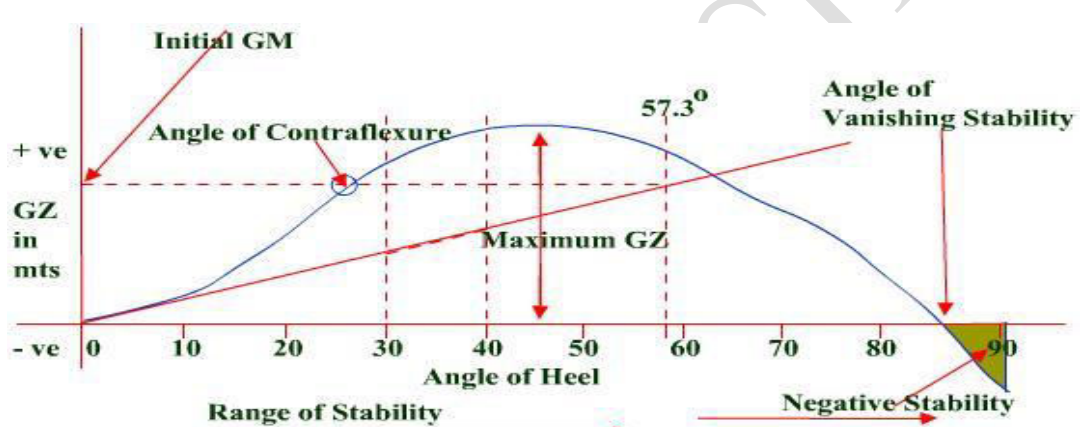
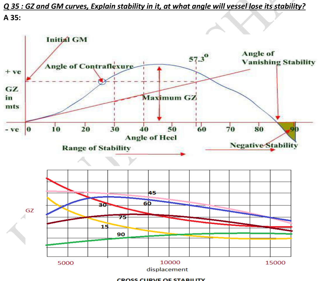
GZ is the righting arm. The curve of statical stability, or GZ curve, is obtained by plotting the righting lever against the angle of heel. It is plotted for a particular KG and a particular displacement, and therefore for a particular voyage condition.
As the ship progressively heels, the righting lever increases to some maximum value and then decreases until, at some angle of heel, it becomes negative — it becomes a capsizing lever.
Reading the curve, on a real ship of this class:
| Feature | Value on the curve | What it means |
|---|---|---|
| Range of stability | 0° to 64° | The range over which the ship has a positive righting lever |
| Angle of vanishing stability | 64° | The angle of heel at which the righting lever returns to zero, or at which the sign of the righting lever changes from positive to negative |
| Maximum GZ | 0.57 m, at about 39° | Found by plotting a tangent to the highest point of the curve |
| Initial GM | found graphically | A tangent is drawn to the curve through the origin; a perpendicular is erected through 57.3° of heel; the two lines are allowed to intersect, and the value of GZ at the intersection is the initial GM |
| Point of inflexion, or contraflexure | about 23° | Where the trend of the curve changes from increasing steepness to decreasing steepness — the angle at which deck edge immersion takes place |
3.2.2 The angle of vanishing stability and the moment at an angle
The angle of vanishing stability is the angle of heel beyond which the vessel will capsize. At that angle the righting lever has returned to zero, so no righting moment remains; past it the lever is a capsizing lever and the ship goes over.
The righting moment at any angle is found from the curve directly:
3.2.3 Cross curves and KN curves
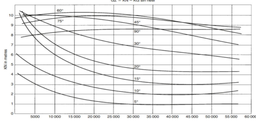
To draw a static stability curve by hand the value of GZ is needed at a number of angles of heel. Those values are not read off one curve — they are read off a family of curves called the cross curves of stability, which are plotted as GZ against angle of heel, one curve for each displacement.
The GZ cross curves themselves have a limitation: they are drawn for an assumed KG, so if the ship's actual KG differs from the assumed value, a correction has to be applied to every righting lever read from them. The way out of that is the KN curve.
KN cross curves of stability. The cross curves are constructed by plotting the righting levers for an assumed height of the centre of gravity above the keel; in some cases they are constructed for an assumed KG of zero. The curves are then called KN curves, KN being the righting lever measured from the keel rather than from G.
The construction is the reason the correction disappears. K is the keel. If, at any angle of heel θ, a line parallel to GZ is drawn from K, the point where that line cuts the vertical through the centre of buoyancy is N. From that figure:
The only unknown quantity in that expression is KN, and KN depends on the ship's form and displacement alone — not on how she is loaded. So a computer-generated plot of KN for a range of displacements, at each heel angle, gives a set of curves valid for every loading condition, and the KG of the actual condition is inserted at the end. Those curves are the KN curves, or cross curves of stability.
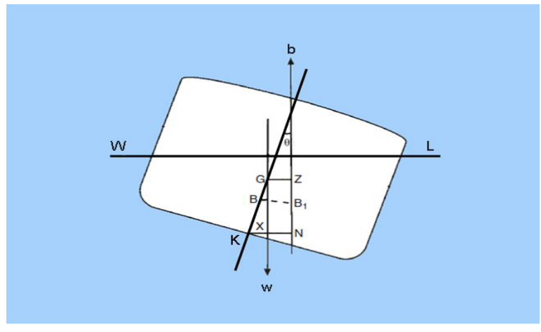
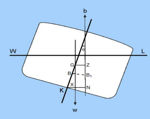
Use on board. The cross curves were developed so that, for any loading condition in which KG is already known, the value of the righting lever can be obtained for all angles of heel. The three facts that make the method work are that KG varies with the loading condition, that KG is always known to the designer and to the master for every condition, and that the angle of heel at any condition is likewise known to both.
Worked through on a real set of KN curves, at a displacement of 40 000 tonnes and KG of 10 m:
| Heel | KN | sin θ | KG sin θ | GZ = KN − KG sin θ |
|---|---|---|---|---|
| 5° | 0.9 | 0.087 | 0.87 | 0.03 |
| 10° | 1.92 | 0.174 | 1.74 | 0.18 |
| 15° | 3.11 | 0.259 | 2.59 | 0.52 |
| 20° | 4.25 | 0.342 | 3.42 | 0.83 |
| 30° | 6.30 | 0.5 | 5.00 | 1.30 |
| 45° | 8.44 | 0.707 | 7.07 | 1.37 |
| 60° | 9.39 | 0.866 | 8.66 | 0.73 |
| 75° | 9.29 | 0.966 | 9.66 | −0.37 |
The last row is the whole point of the table: the lever has gone negative between 60° and 75°, and that is where the ship's range of stability ends for that condition.
GZ = KN − KG sin θ.3.2.4 Dynamic stability
Dynamic stability is the work done in heeling the ship — the energy required to heel her from the upright equilibrium to the angle of heel in question. It is the product of the area under the GZ curve in metre-radians and the vessel's displacement in tonnes, expressed in tonne-metres.
The area under the curve represents the potential energy of the ship, and to incline her to a particular angle a work has to be done to separate G and B vertically. That work is the dynamic stability for that angle of heel. The same quantity is the moment of dynamic stability at a particular angle:
The area is quoted in metre-radians and the displacement in tonnes, so the result is in tonne-metre-radians.
3.2.5 Static against dynamic stability
| Static stability | Dynamic stability | |
|---|---|---|
| Definition | The ability of a ship to regain her upright equilibrium position after the removal of the external factor that caused her to heel | The energy required in heeling the ship from the upright equilibrium to the angle of heel in question |
| The sea it assumes | Stability information under the condition that the outside water is static | Stability information taking account of the dynamic behaviour of the sea |
| How it is expressed | Metacentric height GM for angles of heel up to 10°, righting lever GZ above 10° | The area under the righting-moment curve — that is, the GZ curve multiplied by the ship's displacement in tonnes |
| Unit | Metre | Tonne-metre-radian |
| Uniqueness | The static stability at two different angles of heel can be the same | The dynamic stability at two different angles of heel cannot be the same |
3.2.6 The required area under the GZ curve
Every cargo ship has to satisfy the same set of intact stability requirements, and they are the numbers to answer with — initial GM, the righting lever at 30°, where the maximum occurs, and the three areas under the curve:
| Requirement | Value |
|---|---|
| Initial metacentric height GM | Not less than 0.15 m |
| Righting lever GZ | At least 0.2 m at an angle of heel of 30° |
| Maximum righting lever | To occur at a heel of more than 30°, preferably, but in any case not less than 25° |
| Area under the GZ curve, up to 30° | 0.055 m·rad |
| Area under the GZ curve, up to 40° | 0.090 m·rad |
| Area under the GZ curve, between 30° and 40° | 0.03 m·rad |
| Area between 30° and the angle of downflooding | 0.03 m·rad |
For a tanker the same intact-stability criteria apply under Annex I:
Every oil tanker of 5 000 tonnes deadweight and above delivered on or after 1 February 2002 shall comply with the intact stability criteria above. The angle of downflooding is the angle at which deck immersion takes place, with subsequent water ingress.
Why the maximum GZ must not come before 25°. The angle of downflooding usually occurs at about 25° of heel. Downflooding is the point at which the ship starts to take water on deck and the curve stops being meaningful — beyond it there is no further righting lever to be had, only ingress. Maximum righting lever must therefore already have been reached before that point, so that the greatest righting ability is available at the angle where it is about to be needed; it must not fall in a region of heel the ship will never reach intact.
3.2.7 Negative GM and the shape of the curve
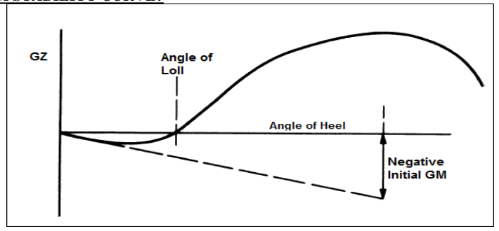
With a negative initial GM, the GZ curve does not start as a rising curve through the origin at all: it starts below the axis. At small angles the lever is negative, so the ship is being pushed further over rather than righted, and the curve only crosses the axis at the angle of loll. Beyond the loll angle a positive righting lever is built up again, so a second, smaller range of stability exists on the other side of the trough. Maximum GZ is lower than it would have been with positive GM, and the range of stability is reduced at both ends.
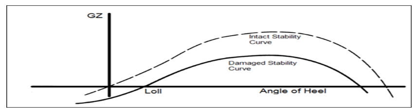
For the effect of damage on that shape, see §3.6.2.
3.3 Stiff, tender and loll
3.3.1 Stiff and tender ships defined
Stiff ship. A vessel is said to be stiff if she has an abnormally large metacentric height. Such a ship may have a short period of roll and will therefore roll uncomfortably. Large GM gives a large righting lever at any angle, and therefore great resistance to rolling.
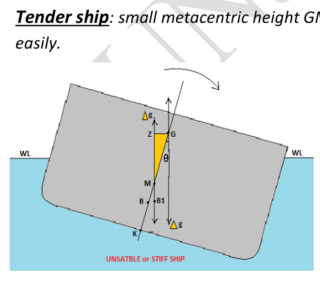
Tender ship. A vessel is said to be tender if she has an abnormally small metacentric height. Such a ship may have a long period of roll, but may list excessively in a strong wind and may be dangerous if a hold is flooded following a collision. Small GM gives a small righting lever at any angle, and she will roll easily.
3.3.2 Stiff against tender, item by item
| Stiff ship | Tender ship |
|---|---|
| Has a large GM because high-density cargo is on the bottom and KG is very small | Has a small GM because most of the loading is on top and KG is large |
| Has a large righting lever | Has a small righting lever |
| Rolls violently and irregularly | Rolls smoothly and regularly |
| The time period to return to the original position is small | The time period to return to the original position is large |
| A very uncomfortable situation | Uncomfortable, but better than the stiff ship situation |
| Structural damage to the ship may occur due to racking | The chance of structural damage to the ship is less |
| Bulk cargo is less likely to shift because the angle of roll is small, but loose gear will be thrown out | There is greater and more prolonged strain on cargo lashings and an increased risk of cargo shift, though to a much lesser extent |
| Severe stresses are set up on the hull | Less severe stresses are set upon the hull |
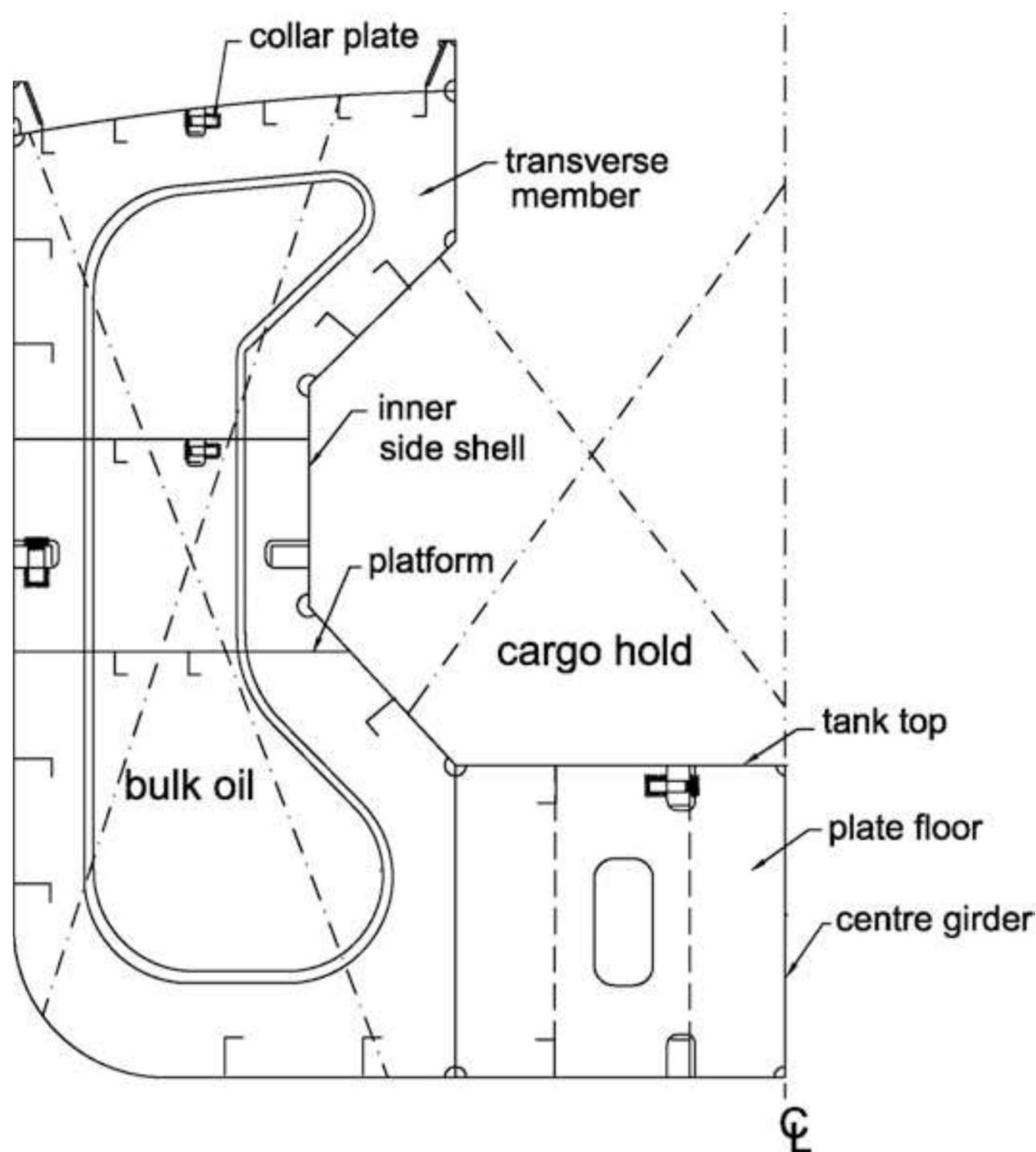
The design case that produces a stiff ship is worth holding on to, because it is a real ship type and not a textbook example. High-density bulk cargo — ore, coal — is where the trouble comes from. The double bottom height of a high-density bulk carrier is made substantially greater than that of an ordinary grain carrier, and one of the reasons is the behaviour of the VCG in the loaded condition:
- The cargo is 7–8 times the density of grain, so it occupies far less space in the hold to bring the ship to her full-load draught. A large part of the hold is left empty, so the cargo can shift as the ship rolls, damage the side shell, and list her — and the permanent heel then costs rudder angle and fuel to correct.
- The vertical centre of gravity sits very low, giving a substantially high metacentric height. That makes the ship stiff: a very high righting moment, a rapid return from any angle of heel, and therefore a roll that overshoots to the other side. The rolling motion becomes severe.
The combination carrier answers both problems at once by raising the tank top — which raises the VCG and reduces GM, making the vessel tender — and fitting inner side shells, which cut the hold volume so that the hold stays full and the cargo cannot shift. The space created by the inner side shells is used for liquid cargo on the return voyage.
3.3.3 The angle of loll
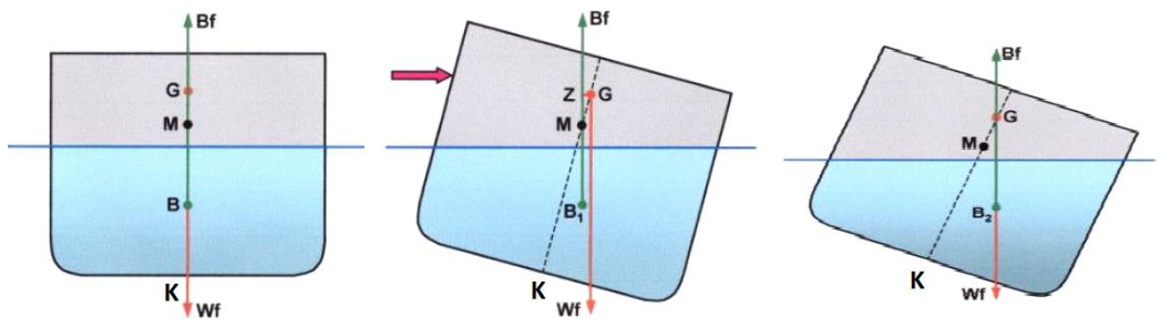
Angle of loll. The angle at which a ship with an initial negative metacentric height will lie at rest in still water. An initially unstable ship heels to a certain angle and ends up in neutral stability; that angle is the angle of loll. Stated the other way round: the angle at which the ship is unstable when upright — that is, has a negative metacentric height — and therefore takes on an angle of heel to either port or starboard.
At the angle of loll:
The mechanism, read off the sequence of figures:
- The ship has an initial negative metacentric height. Any external force starts her heeling.
- The lines of action of the buoyancy Bf and the weight Wf are then arranged so as to cause the ship to heel further over. GZ is a capsizing lever.
- As the vessel continues to heel, the centre of buoyancy moves outward as the underwater volume changes shape. At some stage B comes into the vertical line with G, GZ becomes zero, the capsizing lever disappears, and the ship comes to rest — at the angle of loll.
If the centre of gravity were very high, the ship would not come to rest at all: she would capsize.
3.3.4 Correcting an angle of loll
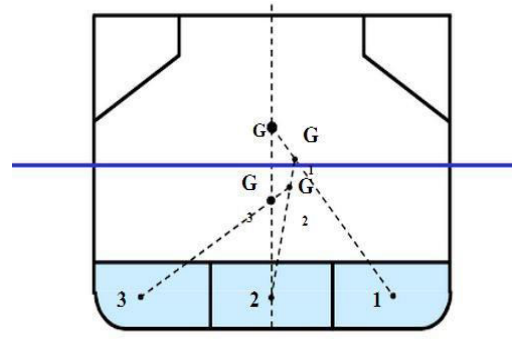
The rule is absolute: an angle of loll can be corrected only by lowering the centre of gravity, not by moving loads transversely. Moving weight sideways addresses a list; it does not touch the reason a lolled ship is lolled. Lowering G is done by moving weight downwards, by adding water ballast in double bottom tanks, or by removing weight above the ship's vertical centre of gravity.
The full procedure as worked through on board:
- First check whether the vessel is listed or lolled.
- Always presume it is lolled, for safety, and work accordingly.
- Calculate the volume of all tanks and check for any slack tanks — if there are any, they are the reason.
- If the port and starboard listing moments are the same, then confirm that the ship has lolled.
- In a listed condition, always try to lower the centre of gravity by discharging the high side of the ballast first.
- Start filling the low side of the tanks, preferring smaller tanks to minimise free surface effect during filling — because if the other side of the tank is filled instead, the listing moment will be enough to capsize her.
- Gradually start filling the mid tank, then the port side tank.
- The vessel should now be upright. Even if she is not, ballast other tanks in the same method.
Why the high side is never ballasted. During a loll, never ballast the high side of the tank. The ship's listing moment to the other side is by itself enough to capsize her.
3.3.5 Where the angle of loll occurs
The angle of loll occurs in timber carriers:
- Timber stowed on deck absorbs moisture as the voyage proceeds, and that raises the centre of gravity.
- Consumption of fuel and water from the lower tanks during the voyage raises the centre of gravity further still.
Those two effects together are enough to take a stiff ship with a positive GM and turn her into an unstable one mid-voyage, which is why the condition is watched on timber deck cargo ships in particular.
3.3.6 Two ships of different breadth
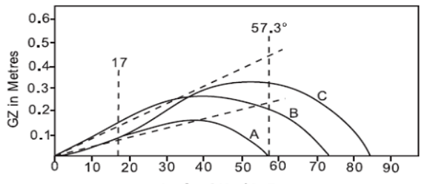
The breadth of the ship is what decides BM, and BM is the whole of the difference between a stable and an unstable ship of the same displacement. For a given waterplane, the metacentric radius rises with the cube of the breadth while the volume of displacement changes hardly at all, so widening the ship raises M faster than anything else in the geometry. Two ships of identical length and draught, one broad and one narrow, will accordingly differ through the entire curve:
- The broader ship has the larger BM and therefore the larger KM and GM, the larger righting lever at every angle, the greater maximum GZ, and the wider range of stability. She is the stiffer of the two.
- The narrower ship has the smaller BM, the smaller GM, the smaller maximum GZ and the narrower range of stability. She is the tender of the two, and with the same KG she may have no positive GM at all.
3.4 Free surface
3.4.1 The free surface effect and its effect on GM
Free surface effect. When a tank on board a ship is not completely full of liquid, and the vessel heels, the liquid moves across the tank in the same direction as the heel.
The chain of consequences:
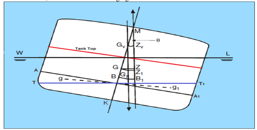
- When the ship inclines to an angle of heel θ, the free surface of the liquid changes from AA1 to TT1, and the centre of buoyancy of the ship shifts from B to B1.
- The volume of liquid in the wedge between A and T has shifted to the lower side between A1 and T1, so the centre of gravity of that volume of liquid has shifted from g to g1.
- Because of the weight shift within the ship, the centre of gravity of the ship shifts from G to G1. The resultant weight of the entire system now acts through a virtual point much higher than the ship's actual centre of gravity: Gv, obtained by extending a vertical line from the new centre of gravity G1 up to the ship's centreline.
- The resultant KG therefore increases, which reduces the metacentric height. The new metacentric height with free surface is GvM and the new righting lever is GvZv, both significantly less than the values without free surface effect.
The effect on the ship, stated as the four links in the chain:
3.4.2 Does the weight of the liquid and the position of the tank matter?
This is the question that separates a memorised answer from an understood one, and the answer is that the two factors behave in opposite ways.
Position — no. The effect of free surface is independent of the position of the tank. A tank may be at any height within the ship, or at any longitudinal position, and the development of a free surface in it will affect the ship in the same way irrespective of its location. The reduction in GM does not depend on how high the tank is.
Density — yes. The reduction in metacentric height due to free surface effect is greater for denser liquids.
Shape — yes, and this is the one that can be designed against. The reduction in stability is directly proportional to the area moment of the free surface about the tank's longitudinal centreline. The smaller the transverse surface area of the free surface, the smaller its area moment of inertia about that centreline, and the smaller the reduction in GM.
The governing expression for the virtual rise of G is:
| Symbol | Meaning |
|---|---|
ρL | Density of the liquid in the tank |
ρS | Density of seawater |
iL | Area moment of inertia of the free surface about the tank's longitudinal centreline |
∇S | Volume of displacement of the ship in seawater |
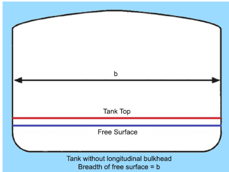
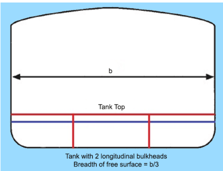
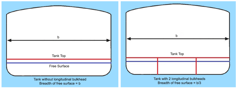
Because the breadth enters that moment of inertia cubed, a tank whose breadth is the full beam of the ship produces a very large reduction in GM, whereas the same tank divided by two longitudinal bulkheads into three equal parts suffers only about a ninth of it. That is why the tank plan of every ship shows the large fuel and fresh water tanks divided into port, centre and starboard compartments.
3.4.3 The GG2 formula and the effect of division
The virtual rise of G is written GG2, and it is a function of the tank's length, breadth and the ship's volume of displacement.
Without division:
With a transverse division, cutting the tank across its length, the length is the dimension that is halved and the expression is unchanged in form:
and the same expression applies with L taken as the length of the division in question.
With a longitudinal division, cutting the tank across its breadth, the breadth is halved and because B enters cubed the effect is far greater:
The free surface effect is still further reduced by longitudinal division than by transverse division. If a tank is subdivided by N longitudinal divisions forming equal tanks, the general expression is:
That is the arithmetic behind the design rule in §3.4.2: two longitudinal bulkheads mean N = 2 and a reduction by a factor of nine.
3.4.4 Pocketing
Pocketing is a second, entirely different method of reducing free surface effect. It occurs when the surface of the liquid contacts the top or the bottom of the tank, reducing the breadth B of the free surface area. It happens at the top of a tank when the tank is filled nearly to its crown, and at the bottom when it is nearly empty: in either case the liquid can no longer run the full width of the tank, and the free surface it presents is shortened.
Two things follow, and both are worth saying out loud:
- Since the effects of pocketing cannot be calculated, it is an indeterminate safety factor.
- The free surface correction will therefore indicate less overall stability than actually exists. Pocketing is a gain the ship gets for free, not a term in the calculation.
3.4.5 Surface permeability, swash bulkheads and sluice valves
Surface permeability. Impermeable objects inside a flooded space — engines, pumps, piping systems and the like — project through and above the liquid surface. They inhibit the moving water, so the "shifting of the wedge" may or may not complete, and the free surface effect is reduced. They also occupy volume, which reduces the amount of flooding water — the movable weight — that can fill the space.
Swash bulkheads, or baffle plates. In addition to providing some structural support, these bulkheads are designed to reduce free surface effect. They are longitudinal bulkheads that hinder, but do not prevent, the flow of liquid from side to side as the ship rolls or heels. They are found in tanks, voids, double bottoms, bilges and similar spaces.
Sluice valves. Sluice valves allow opposing tanks to be cross-connected:
- When large, partially filled tanks are connected, free surface effect increases and the vessel becomes less stable.
- Ships such as oilers and tenders use these valves deliberately to create long, slow roll periods during ammunition handling and refuelling.
That second point is the exception that proves the rule. Normally a slack tank is a liability; on an oiler at a replenishment station it is a tool, because a slow roll is easier to work alongside than a fast one — and the loss of GM is accepted in exchange.
3.4.6 Other contributors to a rise in G
Three further items belong with the free surface effect, because each of them raises G or enlarges a free surface without any weight being added:
- Collapse of a longitudinal bulkhead or a tank bulkhead may lead to a rise in the CG, because it increases the moment of inertia of the free surface. Two tanks have become one.
- Ice build-up on the superstructure significantly reduces stability. It causes unwanted angles of list and unwanted trim conditions, which shift the centre of gravity, and the resulting righting arm is significantly less at all angles of heel.
- The consequences of ice, stated as a set, are a reduction in maximum GZ, in the initial transverse metacentric height, in dynamic stability, and in the range of stability.
3.5 The inclining experiment and the stability booklet
3.5.1 Purpose of the inclining experiment
The inclining experiment is a simple experiment, carried out on the completed ship, to determine the metacentric height and hence the height of the centre of gravity of the ship. Once the height of the centre of gravity of the empty ship is known, its position can be calculated for any given condition of loading.
The primary purposes, stated as three:
- To measure the lightship weight of the ship.
- To find the vertical, longitudinal and transverse positions of the centre of gravity.
- To calculate the metacentric height of the lightship.
It is always conducted by the shipbuilder, because at this stage the shipbuilder must prove to the client that the lightship weight has not exceeded the design value. A weight margin of approximately 15 to 20 per cent is allowed in the technical contract. If the difference between the design lightship weight and that calculated during the inclining experiment exceeds the margin stated in the contract, the shipbuilder must pay a penalty for each extra tonne.
The initial metacentric height of the ship is determined by an inclining experiment after the ship is completely built. The metacentric height is the distance between the centre of gravity and the metacentre, GM, and it is used to calculate the stability of the ship.
3.5.2 The theory and the calculation
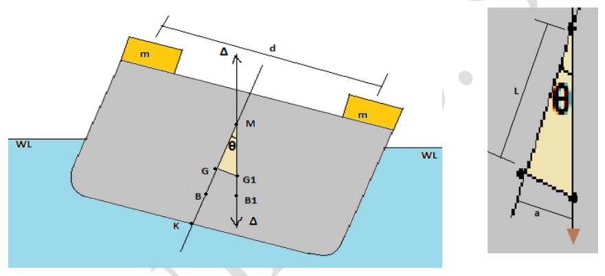
The experiment is commenced with the ship upright. A small mass m is moved across the ship through a distance d. This causes the centre of gravity to move from its original position G on the centreline to G1.
The ship then heels to an angle θ, at which the centre of buoyancy moves from B to B1, into the same vertical line as G1. The vertical through B1 intersects the centreline at M, the transverse metacentre:
therefore GM tan θ = m × dΔ
and GM = m × dΔ × tan θ
To determine the angle of heel it is necessary to suspend a pendulum from, for example, the underside of a hatch. The deflection a of the pendulum is measured when the mass is moved across the deck. If L is the length of the pendulum:
hence GM = m × d × LΔ × a
The height of the transverse metacentre above the keel is then found from the metacentric diagram, and hence the height of the centre of gravity of the ship is determined:
3.5.3 Requirements before and during the experiment
The experiment must be carried out very carefully to ensure accurate results, and the conditions are not negotiable:
- The experiment is carried out when the ship is built completely, or when major structural changes have been done.
- It is carried out with the ship empty, or as near to empty as possible.
- The ship must be in the upright position.
- The ship should be sheltered and in calm water.
- Mooring ropes must be slackened and the ship-to-shore gangway removed.
- Draughts and density of the water are read as accurately as possible.
- All tanks must be empty or pressed up tight, to reduce free surface effect.
- Only those people responsible for conducting the experiment go on board.
3.5.4 Why the ship must be as near empty as possible
The experiment measures the position of G of the ship as she then is. Everything subsequently hung on that figure — the KG for every loaded condition in the stability booklet — is derived from it by taking moments of the added weights about the measured lightship G. That derivation is only as good as the starting value, and it is only clean if the ship is in the light condition when the reading is taken: a small mass moved across a large deck gives a small, measurable heel, and anything else on board that could shift, run to a low corner, or already have a free surface corrupts the value being measured.
3.5.5 Method on board
The experiment is conducted using a stabilograph, consisting of a heavy metal pendulum balanced on a knife edge and connected to a pointer to record the heel angle readings. The step-by-step method:
- At least two pendulums are used, one forward and one aft, placed as far apart as possible and made as long as possible. They are suspended from a convenient point, such as the underside of a hatch.
- A stool is arranged in way of each pendulum on which the deflections are recorded.
- The pendulum bobs are immersed in water or light oil to dampen the swing.
- Four masses — A, B, C and D — are placed on the deck, two on each side of the ship near midships, their centres as far as possible from the centreline.
- The mooring ropes are slackened and the gangway removed; the draughts and the density of the water are read as accurately as possible.
- The inclining masses are then moved, one at a time, across the ship until all four are on one side, then all four on the other side, and finally two on each side.
- The deflections of the pendulums are recorded for each movement of mass.
- An average of these deflections is used to determine the metacentric height.
3.5.6 Why the initial GM is taken at 57.3°
Initial GM is found graphically from the GZ curve: a tangent is drawn to the curve through the origin, a perpendicular is erected through an angle of heel of 57.3°, the two lines are allowed to intersect, and the value of GZ at the intersection is the initial GM.
The number is not arbitrary. 57.3° is one radian:
The tangent at the origin has a slope of GM radians per radian of heel. The height of that tangent above the horizontal at 57.3° — that is, at one radian — is numerically equal to the slope itself, which is GM in metres. Taking the reading at one radian is simply the graphical way of making the ordinate of the tangent equal to the metacentric height.
3.5.7 Contents of the stability booklet
Each ship must be provided with a stability booklet approved by the administration. It contains:
- A general description of the ship.
- Instructions on the use of the booklet.
- General arrangement plans showing watertight compartments, closures, vents, downflooding angles and so on.
- Hydrostatic curves or tables and cross curves of stability.
- Capacity plan and centre of gravity for each cargo stowage space.
- Tank sounding tables showing capacities, centre of gravity and free surface data for each tank.
- Information on loading restrictions, such as a maximum KG or minimum GM curve or table.
- A brief description of the stability calculations done, including the assumptions.
- General precautions for preventing unintentional flooding.
- The inclining test report for the ship.
- Any other necessary guidance for the safe operation of the ship under normal or emergency conditions.
The same document appears in a ship's certificate and plan list simply as the intact stability booklet, carried by every passenger ship and every cargo ship of more than 24 m in length. Where a loading instrument incorporating approved stability software is fitted, that software holds the same data and performs the same checks against it.
3.6 Intact, damage and subdivision
3.6.1 Intact against damage stability
A ship is seaworthy if she fulfils two stability criteria: intact stability and damage stability.
Intact stability is stability of the undamaged ship. Its requirements are the set in §3.2.6, and they are applied to the ship as she is loaded and handled.
Damage stability is stability after flooding. The criterion varies from ship to ship, and the requirement for a given ship is given in SOLAS Chapter II-1. It may be single-compartment flooding, multi-compartment flooding, engine room flooding, and so on. Under all the criteria as applicable, the margin line must not be submerged after the damage.
3.6.2 Transverse stability
Transverse stability is the ability of the vessel to return to the vertical when she has been heeled. The heeling may be caused by an external force, including the action of the sea and swell, and stability has to be maintained even when the vessel has altered the distribution of weights within her — loaded or discharged cargo, ballasted or de-ballasted her tanks, taken in or used up fresh water, fuel or stores.
The two conditions are distinguished by their cause, and the distinction runs through the whole subject:
| Cause | Centre of gravity | Centre of buoyancy | GM | |
|---|---|---|---|---|
| Heel | External — wave, swell, current, wind | Does not change; it depends on mass distribution, and it stays on the centreline | Shifts | Always positive |
| List | Internal — uneven distribution of mass while loading, discharging, shifting, ballasting, de-ballasting or bunkering | Changes, and moves off the centreline of the ship | Shifts | Remains positive |
The practical test follows directly: a heeled ship has a correctable angle, because the cause is outside her; a listed ship has an incorrect loading, because the cause is inside her.
3.6.3 Longitudinal stability
Longitudinal stability explains the location of the centre of buoyancy. It is based on the direction of the wave, and it applies throughout the length of the ship. It can be explained in three cases:
Case 1 — ship in the upright condition. The weather is calm. The centre of buoyancy and the centre of gravity are both situated on the same line, that is, on the centreline of the ship. Weight equals buoyancy, andTrim = draught aft − draught forward = 0. Case 2 — wave coming from aft.Trim = draught aft − draught forward = negative. Trim is negative, hence the centre of flotation is forward. Case 3 — wave from forward.Trim = draught aft − draught forward = positive. Trim is positive, hence the centre of flotation is aft.
3.6.4 Floodable length, permissible length and the factor of subdivision
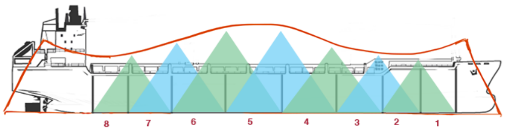
Floodable length. The maximum length of the ship that can be flooded without submerging the margin line. It is the length of the ship that may be flooded without sinking below her safety or margin line. The margin line is the line just below the top of the bulkhead deck.
The floodable length of a vessel varies from point to point throughout her length, and is usually greatest amidships and smallest near the quarter length.
Permissible length. The floodable length of each point along the ship's length is multiplied by the permeability to obtain the permissible length. The permissible length curves for 85 per cent and 60 per cent permeability are incorporated into the floodable subdivision diagram. For machinery compartments — the engine room compartment BC, for example — the vertices of the triangle are checked against the 85 per cent curve instead of the floodable length (100 per cent) curve.
Stated in the other direction, the permissible length is the length between bulkheads on a ship such that it will remain afloat if one or more compartments are flooded; it is some fraction of the floodable length, and the fraction is called the factor of subdivision.
Permeability values used in the subdivision diagram, with the reason for the variation between them:
| Compartment type | Permeability |
|---|---|
| Watertight compartment | 95–97 % |
| Accommodation spaces | 95 % |
| Machinery compartments | 85 % |
| Cargo holds | 60 % |
| Stores | 60 % |
3.6.5 Damage stability and the subdivision index
After flooding in any compartment or hold, the subdivision — the watertight bulkheads — must ensure that the vessel can float and remain stable under moderate environment.
There are three approaches to deciding the number of subdivisions of a ship.
Approach 1 — floodable length and factor of subdivision. To check compliance with this damage stability requirement, the floodable length curve is superimposed on the ship's plan. A two-compartment standard ship is one for which, if two compartments are flooded, the triangle made by joining the two extreme ends of those compartments at the same floodable length lies under the floodable length curve.
Approach 2 — probabilistic damage assessment. Damage stability calculation by probabilistic damage assessment is required by SOLAS Chapter II-1, Part B. It applies to cargo ships of 80 m in length and upwards, and to all passenger ships regardless of length.
This approach uses the concept of probability to ensure that ships can survive damage to their compartment or compartments. Two probability factors are used:
| Factor | Meaning |
|---|---|
p | The probability that a particular compartment or compartments will be damaged in an incident |
s | The probability that the ship will survive if that compartment or compartments is flooded |
Multiplying the two gives the probability of surviving that damage case:
SOLAS requires these to be considered at three draughts:
| Draught | Definition |
|---|---|
Deepest subdivision draught (ds) | The Summer Load Line draught of the ship |
Light service draught (dl) | The service draught corresponding to the lightest anticipated loading and associated tankage, including such ballast as may be necessary for stability and/or immersion |
Partial subdivision draught (dp) | The light service draught plus 60 per cent of the difference between the light service draught and the deepest subdivision draught |
Attained against required subdivision index. As per SOLAS Chapter II-1, Part B-1, Regulation 6, the ship complies with damage stability when:
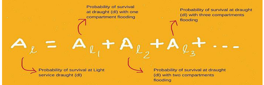
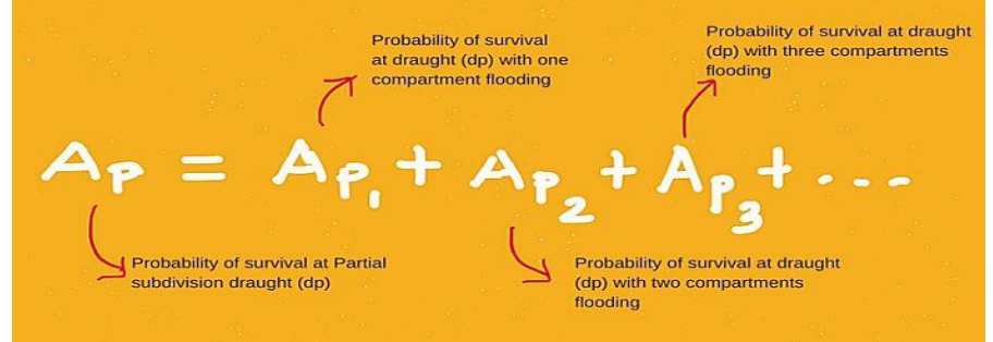
The attained subdivision index (A) is the weighted sum of the survival probabilities computed at the three draughts, itself formed from the sum of the p × s contributions of each damage case at that draught:
where A(s), A(p) and A(l) are the sums of the survival probabilities at the deepest subdivision draught, the partial subdivision draught and the light service draught respectively:
A(p) = Σ p(p) × s(p)
A(l) = Σ p(l) × s(l)
The required subdivision index (R) for cargo ships of more than 100 m in length is given by:
where L is the subdivision length of the ship.
If the attained value is less than the required value, the subdivisions must be rearranged or increased until the attained index exceeds the required index.
Approach 3 — deterministic damage assessment. Unlike the probabilistic method, which uses the concept of probability, the deterministic method defines the variables in quantifiable terms. In this method:
- the damaged area is defined — the damage assumption; and
- the minimum required values of the stability factors are defined — the survival requirements.
In all the cases of damage assumption, the vessel must have stability factor values greater than the survival requirements. Deterministic damage stability calculation is required for all types of tankers.
3.6.6 Damage stability criteria for tankers
An oil tanker is regarded as complying with the damage stability criteria if the following requirements are met:
- The final waterline, taking into account sinkage, heel and trim, must be below the lower edge of any opening through which progressive flooding could take place.
- In the final stage of flooding, the angle of heel due to unsymmetrical flooding must not exceed 25°, except that this angle may be increased to 30° if no deck edge immersion occurs.
- The stability in the final stage of flooding must be investigated, and may be regarded as sufficient if the righting lever curve has at least a range of 20° beyond the position of equilibrium, in association with a maximum residual righting lever of at least 0.1 m within that 20° range; the area under the curve within this range must not be less than 0.0175 m·rad.
- The Administration must be satisfied that the stability is sufficient during the intermediate stages of flooding.
- Equalization arrangements requiring mechanical aids such as valves or cross-levelling pipes, if fitted, must not be considered for the purpose of reducing an angle of heel or attaining the minimum range of residual stability. Sufficient residual stability must be maintained during all stages at which equalization is used.
The equivalent statement of the same requirement, for oil tankers of 150 GT and above delivered after 31 December 1979 under Annex I Regulation 28:
The final waterline shall be below the lower edge of any opening through which progressive flooding may take place. In the final stage of flooding, the angle of heel shall not exceed 25°, and may increase up to 30° if no deck edge immersion occurs. The Administration shall be satisfied that the stability is sufficient during the intermediate stages of flooding.
3.6.7 Engine room flooding and the margin line
The margin line is a line drawn at least 76 mm below the upper surface of the bulkhead deck at side. It is an imaginary line which denotes the limit up to which the ship can be flooded or loaded without sinking.
Where the ship has a continuous bulkhead deck, the margin line is taken as a line drawn not less than 76 mm below the upper surface of the bulkhead deck at side, except that where there is a variation in the thickness of the bulkhead deck at side, the upper surface of the deck is taken at the least thickness of the deck at side above the beam. If desired, the upper surface of the deck may instead be taken at the mean thickness of the deck at side above the beam as calculated for the whole length of the deck, provided that the thickness is no greater than the least thickness plus 50 mm.
In its damaged-stability role the same line is defined as an imaginary waterline considered 75 mm below the uppermost continuous watertight deck. It is the highest permissible location on the side of the ship of any damage water plane in the final condition of sinkage, trim and heel.
What happens if the engine room is flooded. If a ship is damaged, it is considered safe only if the margin line is not immersed. Once the waterline reaches the margin line at any point along the length of the ship, the ship is considered unsafe and evacuation becomes mandatory.
The loss of stability that accompanies that flooding is what the criterion is protecting against. The reduction in metacentric height due to damage can be extrapolated to the stability curve as a reduction in the height of the GZ curve and a reduction in the range of stability. If the loss in metacentric height is such that the remaining maximum righting lever is less than the heeling moment, the ship will capsize. It is therefore the designer's work:
- to design the subdivision so that the remaining righting arm is sufficient up to a certain level of damage; and
- to identify the extent of damage that can be considered safe for the ship.
The engineer's side of the same event is the flooding response itself. Engine room flooding arises from three main causes, and each has its own handling:
Leakage from equipment and system. Call for maximum manpower; find the fault as quickly as possible; start the other circulating system and isolate the leaking pump, pipe or cooler; close the inlet and outlet valves of the affected system; inform the chief engineer and follow his instructions; put a notice or placard on the leaking equipment and trip the breaker until repairs have been done, and do not use the tank until a cement box, welding or other repair has been carried out.
Leakage from an overboard valve. If the leakage is after the valve and the valve holds, shut the valve, provided the system permits normal operation with it closed. If the valve is not holding, identify the leak — it may be the valve stem gland or a flange joint — and repair it. If the system can be isolated without disturbing normal operation, put a blank in the valve. If the repair is temporary, call divers at the next port to blank the valve opening from outside and carry out a permanent repair.
Crack or small hole in the hull. Call for help from the nearest coastal state as soon as the leak is found, because if the leakage grows the ship's stability will be affected. Minimise and then stop the leakage. If the leak is not large, put a cement box in place and repair accordingly. Where the damage is from collision or grounding, the opening in the bulkhead may be too large to stop, and the master has to decide whether the ship is a safe place to remain on board or whether to abandon her; if the abandon-ship signal is announced, the crew musters at their lifeboats.
In any of these cases, if the water level in the engine room rises very high, open the emergency bilge ejector valve with the chief engineer's consent and pump the water overboard. The entry must be made in the Oil Record Book with the date, time and position of the ship and the reason for direct discharge, signed by the officer involved, the chief engineer and the master. The chief engineer is to be reported to immediately in such a condition, without any delay.
3.6.8 Damage control booklet, plan and calculations
The information provided in the damage stability booklet can be divided into three parts:
| Part | Required for |
|---|---|
| Damage control plan | All types of ship |
| Damage control booklet | All types of ship |
| Damage stability calculations | Tankers, under MARPOL Annex I Regulation 28 |
On some ships all of this is found as one booklet called the damage stability booklet; on others there are three separate booklets as above. The document set also appears in the certificate and plan list as the Damage Control Plan and Damage Control Booklet, required for all passenger and cargo ships — plans showing watertight boundaries, compartments and so on.
1. Damage control plan. Required as per SOLAS Chapter II-1, Regulation 19. In simple terms, the plan must show the layout of all the compartments — cargo tanks, ballast tanks, fuel tanks and so on — the means of closure such as valves, watertight bulkheads and hatches or cargo tank domes and their position, and the arrangement for correction of the list during flooding.
2. Damage control booklet. Also required as per SOLAS Chapter II-1, Regulation 19, and it must contain all the information in the damage control plan. Beyond that, it gives the master information and guidance on the actions to take in case of damage to the ship. Those specific actions may include:
- sounding alarms to alert the crew;
- closing all watertight doors and compartments;
- sounding tanks to check where the water is flooding and at what rate; and
- ways to reduce the effect of flooding, such as using pumps to pump out water.
3. Damage stability calculations. These demonstrate compliance with the applicable damage stability regulation. They are made during the design stage of the ship and verified after construction.
3.7 Drydocking and bilging
3.7.1 The three requirements for docking
Three conditions must be satisfied before a ship is brought onto the blocks.
1. Adequate initial GM. When the ship touches the blocks there is a reaction at the point of contact which raises the centre of gravity G and reduces the metacentric height GM. Adequate initial metacentric height is therefore required to compensate for that.
2. The vessel to be upright. While entering the dock the vessel must be upright: there must be no port or starboard list when the ship touches the blocks. If the point of contact between the ship and the keel blocks is outside the centreline of the vessel, it may force the vessel to tip over.
3. Small or moderate trim aft. A moderate trim aft is usually kept when making the ship's keel sit on the keel block. As the water level in the dock lowers, the slight trim allows the ascent of stern and bow in tandem rather than simultaneously, which reduces the load and pressure on the hull and the keel of the vessel.
3.7.2 The critical period
The critical period is the interval of time from when the stern of the vessel touches the blocks to the time when the entire weight of the vessel is borne by the blocks — that is, when the vessel sits completely on them. This period is crucial and requires continuous monitoring.
The word critical means something which has the potential to cause a disaster, and the period is so named for exactly that reason: throughout it, the ship is supported partly by the water and partly by the blocks, and the effective metacentric height is falling towards its block-supported value. The precautions follow directly from the three requirements:
- The vessel must have adequate initial metacentric height, because it will start reducing when the stern touches the blocks.
- The vessel must keep the minimum required trim, so that the critical period is reduced to a minimum; this also reduces the sudden load on the hull and the keel while coming onto the blocks.
Two further points belong with the docking itself. The inspection regime for the ship's bottom is governed by SOLAS Chapter I Regulation 10: a minimum of two inspections of the outside of the ship's bottom in any five-year period, with the interval between any two such inspections not exceeding 36 months; the inspection may be carried out in a dry dock, or as an underwater survey if the classification society decides that the vessel's condition permits it. For the docking of tankers and bulk carriers the detailed requirements are those of the ESP Code — the Enhanced Survey Programme, covering planning, survey on the drydock, survey afloat and completion of the survey report.
3.7.3 Drydock precautions
Docking is a condition of its own, and the following apply once the ship is on the blocks:
- Stability. The ship is no longer supported by buoyancy but by a line of blocks along the keel. GM is reduced, and the ship's ability to resist a transverse moment is at its lowest for the docking. Nothing is moved transversely while the ship is critical.
- Trim. The ship sits to the blocks. The trim aft at the moment of first contact is the one that decides how gently the two ends come down, and it is kept small deliberately.
- Keel loading. The assessment of block loading follows the docking plan, and the plan is followed as written; the docking plan is one of the documents prepared for the drydocking.
- Bottom inspection. The period is used for the survey of the outside of the bottom, and in any case two such inspections must fall within each five-year period at intervals not exceeding 36 months.
The inspection of the bottom itself during drydock covers the sea chest plating and grating, the marine growth prevention system, steam injection and vent valves, gauging of the sea chest plating on older ships, overboard valve connections to the sea chest, the condition of the shell plating, the amount of marine growth before cleaning to evaluate antifouling performance, the welds at the joints after cleaning, the condition of the anodes — normally about 75 per cent of the anodes will have been consumed by the time of the docking — and the welded areas for cracks, corrosion or deformation.
3.7.4 Bilging and lost buoyancy
Bilging is the loss of buoyancy through an opening in the hull. Its place in this subject is the one given to it in the reserve-buoyancy calculation: if mass is added to the ship, or if buoyancy is lost through bilging, the reserve buoyancy is converted into buoyancy by increasing draught. The ship answers a hole in exactly the way she answers an added weight — by going deeper — and the reserve buoyancy above the waterline is what pays for both.
The practical consequence is a design point, and it is one of the reasons a tanker is assigned less freeboard than a bulk carrier of the same size. Following a bilging incident, what decides how much water enters is permeability, not the size of the hole:
- A tanker has a permeability of only about 5 per cent in an oil-filled tank, so far less water enters for a given compartment volume.
- A tanker has more pumps, so ingress can be controlled quickly.
- A tanker has greater subdivision, by additional longitudinal and transverse bulkheads.
- A tanker normally carries lesser density cargo, giving greater buoyancy, and has greater GM values.
- A tanker has much smaller deck openings in the main deck, so less water is taken on deck.
3.8 Damping the roll
3.8.1 Bilge keels
Bilge keels are the standard, passive answer to a ship that rolls too easily. Plates project from the turn of the bilge and extend over the middle half to two-thirds of the ship's length. They cause a body of water to move with the ship and create turbulence, thus damping the motion and causing an increase in period and a reduction in amplitude.
In construction terms:
- The bilge keel fits along the bilge radius on either side of the ship, for nearly half its length.
- It fits at right angles to the bilge radius plating.
- The outer end is riveted or lightly welded, so that the outer joint is easy to break and leaves the hull undamaged.
- Bilge keels are tapered at the ends to minimise hydraulic drag.
- They are not fitted directly to the hull plating: a ground bar is attached to the bilge plate, and the ground bar is connected to the shell by a continuous fillet weld.
- The web must be deep enough to penetrate the boundary layer of water travelling with the ship, but if the web is too deep the force of the water when rolling may cause damage.
- Bilge keels of 250 mm to 400 mm in depth are fitted to oceangoing ships, and they extend for about one half of the length of the ship amidships, tapered gradually at the ends.
3.8.2 Tank stabilisers
There are three basic systems of roll-damping using free surface tanks: passive tanks, controlled passive tanks and active controlled tanks.
- These systems do not depend on the forward movement of the ship, and are therefore suitable for vessels such as drill ships.
- In introducing a free surface to the ship there is a reduction in stability, which must be considered when loading the ship. This is the free surface effect of §3.4 being paid in exchange for roll damping.
Passive tanks. Two wing tanks are connected by a duct having a system of baffles, and the tanks are partly filled with water. When the ship rolls, the water moves across the system in the direction of the roll. As the ship reaches its maximum angle and commences to return, the water, slowed by the baffles, continues to move in the same direction. A moment is thereby created which reduces the momentum of the ship, and hence the angle of the subsequent roll.
The critical parameter is the depth of water in the tanks. For any given ship it depends on the metacentric height, and the tank must be tuned for each loaded condition by adjusting the level; otherwise the movement of the water may synchronise with the roll of the ship and create dangerous rolling conditions. Alternatively the cross-sectional area of the duct may be adjusted by means of a gate valve.
Controlled passive tanks. The principle of action is the same, but the transverse movement of the water is controlled by valves operated by a control system similar to that used in the fin stabiliser. The valves may be used to restrict the flow of water in a U-tube system, or the flow of air in a fully enclosed system. The mass of water required in the system is about 2 per cent of the displacement of the ship.
Active controlled tanks. Here the water is positively driven across the ship in opposition to the roll. The direction of roll, and hence the required direction of the water, changes rapidly, so it is necessary to use a uni-directional impeller in conjunction with a series of valves. The impeller runs continually and the direction of the water is controlled by valves.
Active fins. Fins work on a different principle: a sensitive gyro system senses the rolling motion of the ship and sends a signal to the actuating system, which in turn causes the fins to move in a direction such as to create forces opposing the roll. The actuating gear is usually electro-hydraulic.