
The Thrust Block and Thrust Shaft — Clearance, Pads and Support
The thrust block is the one bearing in the shaft line that takes the ship's drive out of the shaft and puts it into the hull.
Key Principles at a Glance 5 points
- The block does two jobs: it transfers the forward or astern propeller thrust to the hull, and it limits the axial movement of the shaft for the protection of the main machinery.
- Axial clearance is essential to allow the oil wedge to form; too little gives high bearing temperature, power loss and failure, while too much harms nothing in the block but lets the shaft move further than it should.
- The clearance is about 1 mm total and is measured by jacking the shaft to each limit of travel and reading a dial gauge — a feeler in the pad/collar gap damages the pad and can read anything you like.
- The block is sited hard against the propulsion machinery so that differential expansion of hull and shaft, which can reach 20 mm in a midship-engined refrigerated cargo ship, is taken out close to its source.
- It also damps axial vibration of the whole shaft line, and where that damping fails the result is thrust block rock, panting of the tank top and structural damage.
1. What it does
The thrust block is jacked and gauged, never felt with a feeler in the pad gap. The total axial movement is about 1 mm, it is measured with a dial gauge against the shaft end, and the figure is recorded. A feeler between the thrust pad and the collar damages the pad and can read anything you like.
The main thrust block transfers the forward or astern propeller thrust to the hull and limits axial movement of the shaft.
Those are two separate duties and both matter:
- Transmitting the thrust. The propeller's push arrives along the shaft as an axial force, and the collar passes it into the pads and so into the casing and the structure beneath. This is the load that drives the ship, and it is the reason the block is bolted to the strongest piece of structure in the engine room.
- Limiting the axial movement. Without the block the shaft would be free to slide within whatever end float the couplings allowed, and that would wreck the main machinery. Axial movement of the shaft must be limited for the protection of the main machinery.
Some thrusts are housed in the after end of large slow-speed diesels, or against gearboxes. Where that is done, the thrust bearing is inside the engine or the gearcase and the shaft line has no separate block. The checks are the same; only the access is different.
2. The axial clearance, and why it is essential
Some axial clearance is essential to allow the formation of an oil film in the wedge shape between the collar and the thrust pads. Without the clearance there is no wedge, and without the wedge there is no film, and without the film the pads run on the collar.
The clearance is also needed to allow for expansion as the parts warm up to operating temperature.
The actual clearance required depends on the dimensions of the pads, the speed, the thrust load and the type of oil employed. There is no single figure; the maker's figure for the installation is the one to use.
Two failure modes follow, and they are not symmetrical:
- If the axial clearance is too small, the result is high bearing temperature, power loss and failure.
- If the clearance is larger than necessary, no harm is done to the thrust bearing pads — but the axial movement of the shaft is larger than it should be, and that is a risk to the main machinery rather than to the block.
So the block itself is tolerant of too much clearance and intolerant of too little, which is why a thrust bearing that is running hot is treated as an emergency and one with a slightly generous float is not.
3. Checking the thrust clearance
The accepted method is to jack the shaft axially to the end of its travel in one direction, and then back to the limit of travel in the other. The total movement of the thrust shaft — about 1 mm being typical — is registered on a dial gauge.
Done properly, on a shaft with the top cover removed, the sequence is:
- Remove the top cover.
- Force the shaft aft by means of a screw jack placed between the casing and the back of the coupling, until the collar is hard up on the pads.
- Check that the shaft is truly central in the journal bearings while it is in that position.
- Test that both liners are bearing equally on the casing.
- Take a micrometer or dial gauge reading of the shaft position.
- Repeat the operation moving the shaft forward, and take a second reading.
- The difference between the two readings is the total clearance.
If the clearance is excessive or too small, it is adjusted by subtracting or adding shims to the distance pieces on the back of the pad carriers.
Feelers can be used as an alternative between the thrust ring and the casing — but the use of feelers in the thrust pad/collar gap is likely to cause damage and may give a false reading. The distinction matters: the gap between the thrust ring and the casing is a stationary clearance that a feeler can be laid in without harm, while the pad/collar gap is the working surface of the bearing.
The clearance is also measured using wedges or by hydraulic ram movement on some installations, and on others the block is fitted with an indicator for the purpose (section 8).
4. Where the block is sited, and why
The siting of the main thrust block close to the propulsion machinery reduces any problems due to differential expansion of the shaft and the hull.
The size of that problem is worth seeing. The low hull temperature of midship-engined refrigerated cargo ships caused a contraction relative to the shaft of perhaps 20 mm. A 20 mm change in the length of the shaft line, taken out at the thrust block, is the difference between a correctly loaded thrust bearing and a destroyed one.
Variations can also be caused by changes in water temperature or by heating of fuel tanks. Both are normal operating conditions, not faults.
The other problems associated with the stern tube end of the shafting system are the ones already met in Chapter 1 — whirl of the tailshaft, relative movement of the hull, and misalignment due to droop from propeller weight. Siting the thrust block forward, hard against the engine, keeps the thrust end of the shaft line as stable as it can be made and leaves the after end to do what it must.
Deformation produced by the thrust load can itself cause misalignment problems unless suitable stiffening is employed, and this is particularly true of an end-of-gearbox installation, where the block is mounted on the gearcase rather than on the tank top.
5. The support, and what the thrust load does to it
The substantial double bottom structure under the main propulsion machinery provides an ideal foundation for the thrust block, and a further reason for siting it close to the engine.
The upright thrust block and any supporting stool must have adequate strength to withstand the effect of loading which tends to cause a forward tilt. The consequence of insufficient strength is that the aft journal of the block lifts — where one is fitted — and the shaft is misaligned.
Axial vibration of the shaft system, caused by the slackening of the propeller blade load as it turns in the sternframe, or by the splay of diesel engine crankwebs, is normally damped by the thrust block. Where that damping fails, the result is serious: vibration problems have sometimes caused thrust block rock, panting of the tank top, and structural damage.
So the block is not only a bearing. It is a damper in the axial mode of the whole shaft line, and a thrust block that has been found loose on its chocks is a structural problem as well as a bearing problem.
6. The pads
The pivot position of the thrust pads may be central or offset.
| Pad | Interchangeable? | Where used |
|---|---|---|
| Offset pivot | Interchangeable only in thrust blocks for direct reversing engines, where the direction of load and rotation changes | Direct reversing engines |
| Offset pivot | Not interchangeable — two sets are required | Non-reversing engines, and controllable pitch propeller installations |
| Central pivot (raised) | Interchangeable | Any |
The reason for the distinction is the same one that makes the tilting pad work: the pad has to present a converging wedge to the oil, and the wedge is only convergent in one direction of rotation. A pad with an offset pivot will only work on one side of a reversing engine, so a reversing installation carries pads for ahead and pads for astern, and they must not be mixed up.
Some modern thrust blocks are fitted with circular pads instead of the familiar kidney shape. A comparison of the pressure contours on conventional kidney-shaped pads and on the circular type shows why the circular ones are effective — the contour is more nearly concentric with the pad, so more of the pad carries pressure.
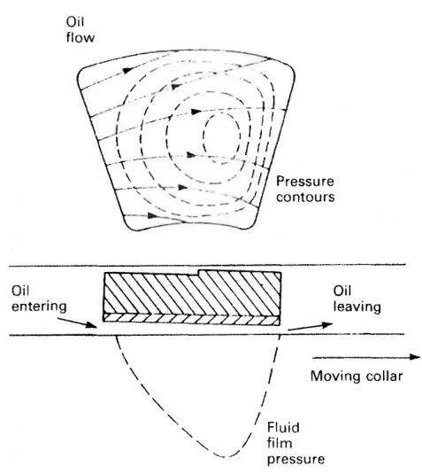
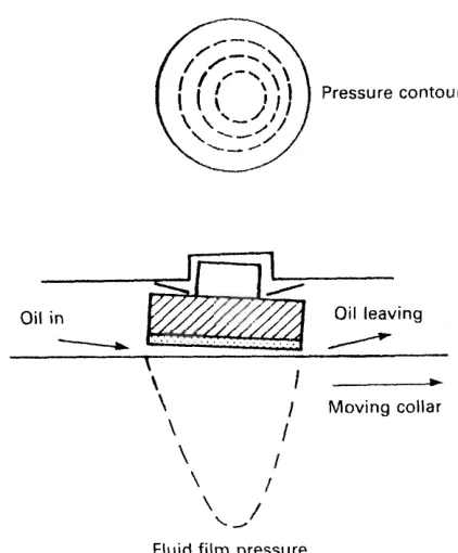
The radial pivot line on the pad back varies from half to two thirds of the pad width from the leading edge. Theoretically the pivot line should be nearer the outlet edge, to coincide with the point of maximum pressure; in practice a central pivot is often satisfactory. In place of a pivot line, a hardened pivot stud is commonly used, especially on smaller types.
7. The block in detail
Modern types work on the Michell principle. The thrust of the collar is transmitted through the oil film and the pads to the casing. The white metal surface would be more likely to yield than the oil film at pressures as high as 500 bar — the compressive yield of white metal is of the order of 560 bar, or 56 MN/m² — so the white metal, not the oil, is the limiting element.
The oiling arrangement is a working part of the design:
- An oil scraper bears on the outer periphery of the thrust collar and delivers oil to the reservoir, from where it cascades on to the pads and bearings.
- The pads fit radially in inverted horseshoe castings, secured circumferentially by a stop.
- The castings back on to liners, which locate the pads fore and aft and fix the clearance. The clearance is adjusted at these liners.
- The lower half casting acts as an oil reservoir sump, provided with an oil level gauge glass and a cooling coil.
- The total oil clearance is approximately 1 mm for a 500 mm diameter shaft.
- The wedges at the base have a slow taper of about 20 mm/m, and act to relieve the holding-down bolts of shear. The floors in the double bottom tank below the thrust stool are closely pitched for the same reason.
8. The Michell thrust indicator
A thrust block can be built with the means to read the thrust while the ship is running.
The standard block is modified so that a cast steel shoe is replaced by a forged mild steel one having a number of holes in the back making up interconnected oil cylinders. A hand pump, pressure gauge, piping and relief valve are provided.
Under oil pressure from the hand pump the internally formed pistons move forward, gradually transferring the thrust load from the liners to themselves. The thrust shoe now floats on the pistons, and the pressure is read on the gauge. When half the axial clearance has been traversed, the relief valve lifts, preventing over-pumping. The piston loading pressure is about 175 bar.
Astern thrust can be measured by a duplicate arrangement on the other side of the collar.
The value of the instrument is that it gives the actual thrust figure in service rather than a calculated one, and it does it without disturbing the block.
9. A thrust bearing running hot
The thrust bearing has the smallest oil clearance in the whole shaft line — about 1 mm total end float on a 500 mm shaft — and the highest unit pressure. It is therefore the bearing that fails first when anything is wrong.
The order to work in:
- Check the oil. Level, condition, and whether the cooler is passing water into the sump.
- Check the cooling water. A cooling coil choked with scale raises the oil temperature and drops the film's viscosity, and the bearing temperature follows.
- Check the thrust clearance by jacking, as in section 3, and compare it with the recorded figure.
- Check the alignment — a thrust block that has tilted forward is transferring load to the after journal and altering the shaft line, and the two faults come together.
- Check for thrust block rock. If the block has moved on its chocks, the fault is in the structure under it, not in the bearing.
A thrust bearing is not adjusted in service beyond the oil and the cooling. Any change to the pad carriers or the liners is a drydock job with the shaft line supported, and the clearance is set against the maker's figure and recorded.