
Split Stern Bearings and Withdrawable Stern Gear
The stern tube bearing is the hardest part of the shaft line to reach, and the traditional answer — drydock the ship and draw the shaft — costs a docking every time the bearing has to be looked at.
Key Principles at a Glance 5 points
- Split stern bearings exist so that the bearing and tailshaft can be examined without drydocking, and every system rests on the same two ideas: the bearing splits on the horizontal centre line, and the stern bearing space can be sealed and drained afloat.
- The Glacier-Herbert bearing is installed from the outboard end with an SKF oil injection coupling at the inboard end, and carries two inflatable seals with individual air supplies — one supply would mean a single failure opened the space to the sea.
- The Ross-Turnbull Mark IV is chocked in the stern frame boss and held vertically by two 50 tonne Pilgrim jacks, with 30 tonne jacks for lateral location, runway tracks above and skates below.
- On the Mark IV the shroud formed by the stern boss acts as a propeller support cradle as well as a sealing face, so the propeller carries the shaft once the chocks are out.
- Withdrawable stern gear draws the whole unit inboard along the shaft with the propeller and shaft left coupled, at the cost of being more expensive than the conventional design.
1. Why split bearings exist
Work on a stern bearing afloat is only possible because the stern bearing space can be sealed off and drained first. The inflatable seals, the maintenance seal or the bandage go on before anything is loosened, the space is drained and proved, and only then is the bearing opened. Nothing is undone on the strength of a seal that has not been proved.
To avoid the necessity for drydocking when an examination of the stern bearings and tailshaft is needed, split stern bearings were developed. A suitable outboard sealing arrangement and design permits the two halves of the bearing to be drawn into the ship, exposing the shaft and the white metal bearing.
Every one of the systems in this chapter is built on the same two ideas:
- the bearing is split on the horizontal centre line, so that the two halves can be separated and moved;
- the stern bearing space can be sealed from the sea and drained, so that the work can be done with the ship afloat.
The rest of the design is the mechanism for lifting, supporting and sliding the halves — jacks, chocks, skates, trolleys and rails.
2. The Glacier-Herbert stern bearing
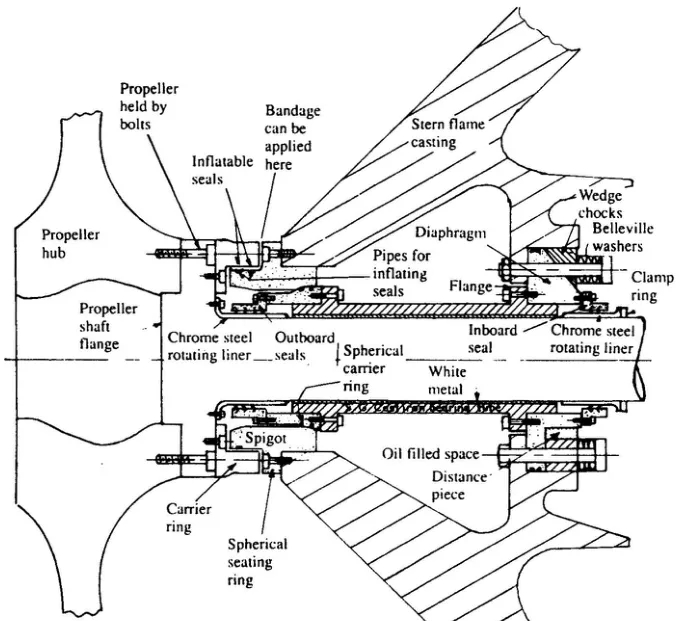
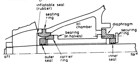
In the Glacier-Herbert system the two completely symmetrical bearing halves are flanged along the horizontal centre line and held together by bolts.
- The after end of the bearing carries a spherical support ring, to which the outboard seal housing is bolted.
- The spherical support ring rests in a carrier ring which is bolted to the after end of the stern frame boss.
- The forward end is supported by a circular diaphragm bolted to a flange provided in the stern frame casting. This diaphragm also acts as a carrier for the forward seal.
- A series of axial bolts, fitted with Belleville washer packs to ensure virtually constant loading, hold the diaphragm firmly in position, along with the bolts securing the spherical seating ring.
This arrangement permits sloped alignment of the bearing, to give full support to the drooping tailshaft. Chocks are used to hold the bearing positively in its final position. The Belleville washers are what allow the diaphragm to stay firmly bolted while the bearing and its housing expand differentially.
The bearing tube is of spheroidal graphite cast iron and white metal lined. It is split along the horizontal, and the two halves are bolted together through flanges along the horizontal join.
Alignment of the bearing tube can be adjusted by the distance pieces and wedge chocks which hold the diaphragm.
The stern frame is fully machined before being welded into the hull of the vessel. The bore for the spherical seating ring can be further machined for adjustment if necessary, but controlled welding is used to maintain alignment during hull construction.
The shaft is installed from the outboard end, with its rotating liner and carrier ring assembled. The shaft inboard end is fitted with an oil injection coupling — the SKF muff coupling of Chapter 4.
3. Sealing the space, and working afloat
The propeller shaft is flanged at the after end and the hub of the propeller is bolted to the flange. On the inboard side of the flange there is a carrier ring bolted on, which forms a shroud around the spigot projecting aft from the spherical seating ring.
Two inflatable seals with individual air supplies are fitted in the periphery of the spigot. These can be inflated to provide a seal against the inside of the carrier ring, sealing the stern bearing space. With the space sealed, work can be carried out on the stern bearing and seals without the necessity of drydocking.
An alternative to using the inflatable seals is to apply a bandage around the small gap between the carrier ring and the spherical seating ring. The bandage is the answer when the inflatable seals themselves are the thing being worked on.
The propeller shaft has two short rotating liners of chrome steel. The liner at the after end is bolted to the propeller shaft flange; the inboard liner is fixed by a clamping ring. These liners act as rubbing surfaces for the rubber seals. The outboard and inboard seal housings are attached to the spherical seating ring and the diaphragm respectively.
The Glacier-Herbert stern bearing can be dismantled without drydocking, if necessary for maintenance or inspection. That sentence is the whole case for the system.
The individual air supplies to the two inflatable seals matter. With one supply, a single failure deflates both, and the bearing space is open to the sea with the bearing half way out.
4. The Ross-Turnbull split bearing, Mark I
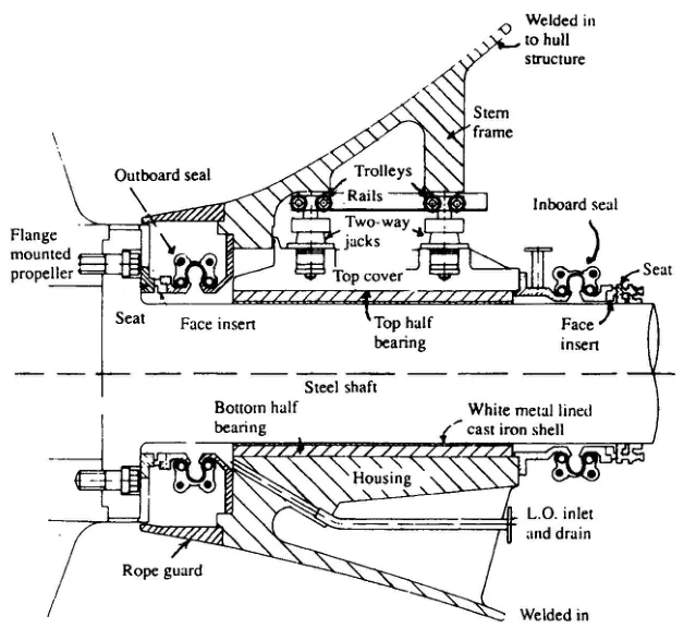
The complete bearing consists of a steel casting which is welded in to become part of the stern frame. A welding sequence is used to maintain bearing alignment during the operation. Installation time is reduced by this method as compared with boring out the stern frame.
The shaft rests on a white metal lined cast iron shell in the housing. This forms the bottom half of the bearing. The top half bearing is secured by hydraulically operated jacks which are mechanically locked by nuts.
The double-acting jacks are also used to lift the cap clear of the shaft, thus automatically bringing trolleys into contact with a built-in overhead rail which enables the cap to be drawn forward.
Examination of the forward seal, bearing and tailshaft can be carried out afloat, at loaded draught, if necessary:
- The lubricating oil is drained and the forward seal released and drawn forward.
- The top half bearing is lifted hydraulically and moved forward on the overhead rail.
- The tailshaft can then be visually examined and crack detected back to the propeller flange.
- The full tailshaft surface is exposed by operating the turning gear.
- The alignment of the tailshaft relative to the bearing is checked by means of feeler gauges.
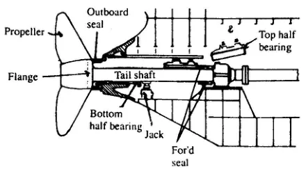
Full inspection or replacement of the outboard seal, and removal of the propeller mounting bolts for inspection and crack detection, is carried out from outside the vessel after trimming or drydocking and removing the rope guard. Both seals are fully split, being of Crane manufacture (Chapter 10).
To examine or replace the bottom half bearing whilst the ship is afloat, the shaft is supported by a jack positioned forward of the bearing, and the bottom half bearing is moved forward, rotated around the shaft and lifted clear.
5. The Ross-Turnbull Mark IV bearing
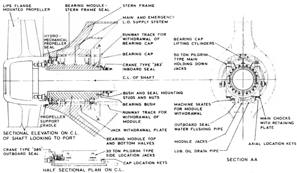
The Ross-Turnbull split stern bearing has a bottom half bearing which is chocked on to two horizontal fore and aft machined surfaces within the stern frame boss.
- The whole bearing is held in position vertically by two 50 tonne Pilgrim type jacks, the chock thickness determining the bearing height. These jacks also hold the top half of the bearing in place.
- Lateral positioning of the bearing is by 30 tonne Pilgrim type jacks arranged on each side of the bearing.
- A running track is arranged above the bearing to allow easy transport of the top half.
- Skids are provided below the bearing to provide easy transport of the bottom half.
Later versions of the stern bearing have a number of changes in design. These allow all maintenance and surveys to be carried out with the vessel in the water, and bearing alignment can also be adjusted.
The top half bearing is removed in much the same way as before, after the inboard seal has been pulled forward. However, a shroud has been extended back from the stern frame casting so that it will act as a propeller support cradle. The casting also has a hydraulic/mechanical sealing ring, used to close the gap between the shroud on the forward end of the propeller boss and the stern frame. The position of the seal is such that the outboard working seal and the propeller flange bolts can be inspected or changed.
To carry out work on the outboard fittings, the maintenance seal is engaged hydraulically and mechanically locked in position. The space inboard of this auxiliary seal is drained before removing the bottom half bearing. That is the sequence the operating rule at the head of this chapter is about.
6. Removing the bottom half of a Mark IV
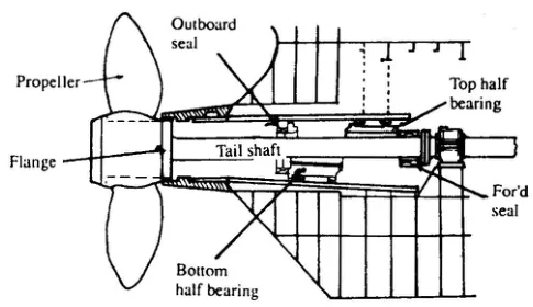
When in working position, the bottom half of the stern bearing is clamped by jacks on either side. It is located by axial restraining keys and rests on chocks which are fitted after alignment. The top half bearing acts as the top clamp.
To remove the bottom half, after clearing the top:
- Portable hydraulic jacks are placed under the bearing, and the complete assembly of bearing, propeller and tailshaft is lifted so that the main chocks can be removed.
- Skates are placed under the bearing at the same time.
- With the chocks out, the assembly is lowered until the propeller is resting in the shroud which is part of the stern boss.
- Further lowering of the jacks brings the bottom half bearing away from the tailshaft and on to the machine skates.
- The jacks are removed and the bottom half bearing is brought forward on the skates, together with the seal face and the bellows section of the oil seal.
- The complete shaft is then exposed for examination and crack detection.
- Removal of the split seal gives access to the bolts and dowels in the propeller flange, without disturbing the propeller.
The shroud is doing two jobs at once: it seals the bearing space, and it takes the weight of the propeller and shaft once the chocks are out. Both have to work before the bottom half can come away.
An oil circulating system with a cooler is necessary for split stern bearings. Water in the aft peak has a cooling action on stern tubes which are oil lubricated, but the accessibility of the split bearings means that they are situated in a void space — so the cooling has to be provided. Oil pressure is kept higher than the external sea water pressure by a header tank arrangement or by a pneumatically pressurised compensating tank. The oil is pump circulated, or may be caused to flow around the system by the pumping action of the bearing.
Instruments are fitted for readings of temperature, pressure, level and flow, with alarms as necessary.
7. The withdrawable stern gear system
The advantage of this arrangement is that inspection, re-alignment or repair can be carried out quickly with the ship afloat, and without the need to disturb the propeller or uncouple the shaft.
It can be used with fixed or controllable pitch propellers, flange or cone mounted, and with most types of seal.
With the bearing, split in halves, withdrawn, the propeller and shafting weight is supported on a ring permanently secured to the stern frame. There is an integral tube-bearing, split in halves, which is fitted or removed from inboard.
The whole unit, including the outer seal, can be moved along the shaft inboard for inspection.
Note also the more modern practice of hydraulic floating a keyless fit, with a taper of 1:30, with the advantages of simplicity and reduced stress factors. Closure is with a hydraulically tightened nut. The unit is generally more costly than the conventional design.
Short, large diameter — up to 1300 mm — spherical SKF roller bearing units are available, capable of inward withdrawal. Connection between intermediate and propeller shaft is by SKF oil injection coupling, and standard inner and outer seals are used. The clearance would be about 0.8 mm.
8. Alternative stern gear — the propeller with its own bearing
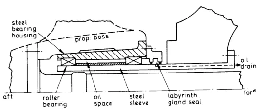
The tendency to fit increasing diameter and weight propellers, in excess of 70 tonnes, so as to drive very large vessels with low revolutions to give higher performance, has made increased shaft flexibility and reduced bending moments very desirable.
The propeller has its own self-contained bearing, and the drive torque shaft is more flexible. Hollow helical — spiral spring — roller bearings are used, giving differential radial expansion allowance and flexibility to shock loading, with plain outer races allowing shaft axial movement.
Note the flanged connection to the propeller boss. This is simple and trouble free, but it requires a special muff coupling at the inboard end to allow withdrawal aft (Chapter 4). Astern thrust resistance is increased with an inner nut.
A similar design is available utilising a plain bearing inside the propeller boss in place of roller bearings. If shaft withdrawal inboard is essential, a cone and taper with a nut arrangement can be used to secure a flanged coupling for bolting to the propeller boss.
9. Choosing between them
| System | What it gives | What it costs |
|---|---|---|
| Conventional stern tube | Simplicity; no moving seals to work afloat | Drydocking to examine the bearing or draw the shaft |
| Glacier-Herbert split bearing | Bearing and seals worked on afloat; sloped alignment to suit the drooping shaft | Two inflatable seals that must both hold; complex spigot and carrier ring assembly |
| Ross-Turnbull split bearing | Bottom half, top half and tailshaft all reachable afloat | Heavy Pilgrim jacking, chocking and skates; needs a full oil circulating and cooling system |
| Withdrawable stern gear | Whole unit drawn inboard along the shaft, with the propeller and shaft left coupled | More costly than the conventional design |
| Alternative stern gear | Very large propellers carried without overloading the shaft | A bearing inside the propeller boss, which is the least accessible place on the ship |
All of them depend on the same thing: the stern bearing space has to be sealable and drainable. The seal that does it — inflatable, maintenance seal or bandage — is the first thing to be proved and the last thing to be relied on.