
Oil Lubricated Stern Tubes — White Metal, Lip Seals and Header Tanks
The oil-lubricated stern tube is the modern arrangement.
Key Principles at a Glance 5 points
- Oil replaced water to put a white metal bearing where the wooden stave was, drop the full-length liner, keep the sea and its sand out of the bearing, and carry the heat away to a cooler.
- Oil pressure is maintained just above the sea pressure at the same depth by a header tank, so the seals have to deal with the movement of the shaft rather than with a pressure difference.
- The white metal bearing is only two shaft diameters long, which keeps the load below 0.8 N/mm²; weardown must not exceed 2 mm and the period between inspections is about six years.
- The seal material must not exceed 110 °C, which is why the inboard seals — having no sea to lose their heat to — depend on oil circulation between the two inboard seals and the header tank.
- The chrome liners groove under the lip seals, and the two remedies are a ceramic filler in the groove or a distance piece to displace the seal on to a fresh band of the liner.
1. Why oil replaced water
The stern tube oil pressure is kept slightly above the sea water pressure at the same depth, so that the leak, if there is one, is oil out rather than sea water in. The header tank is the device that does it, its level is checked, and the aft peak water level is kept above the tube. A stern tube running at less than sea pressure is a stern tube taking sea water.
Progress from sea water to early oil-lubricated stern tubes involved an exchange of the wooden bearing in its bronze sleeve for a white metal lined cast iron bush. Oil retention and the exclusion of sea water necessitated the fitting of an external face type seal. The stuffing box was retained in many early oil-lubricated stern tubes, at the inboard end.
In oil-lubricated bearings the shaft does not require a full-length protective bronze sleeve, because the oil keeps the sea away from the steel. What it needs instead is a short, hard rubbing surface where the seals run — a chrome steel liner at each end.
The advantages over the water-lubricated tube:
- the bearing is white metal, which carries far more load than a wooden stave and does not swell;
- the shaft does not need a full-length liner, so there is no liner to crack along the bearing;
- the sea is kept out of the bearing, so there is no sand, no sediment and no galvanic corrosion at the bearing;
- the oil carries the heat away to a cooler, rather than relying on the sea water flow through the bearing; and
- the seal is a replaceable unit rather than a packed gland that has to be adjusted and re-packed.
The cost is that the seal is the weak point, and that a seal failure lets oil out into the sea or sea water into the oil.
2. The Simplex type stern tube
The later designs of oil-lubricated stern tube are fitted in a stern frame with an elongated boss, to provide better support for the white metal lined bearing.
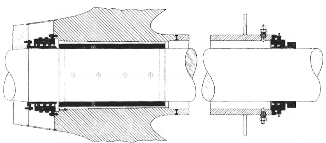
The forward part of the stern tube is fabricated and welded direct to the extension of the stern frame boss and into the aft peak bulkhead.
Oil pressure within the stern tube is maintained at approximately the same level as that of the surrounding sea water by a header tank. That is the whole principle of the arrangement: with the internal pressure matching the sea pressure at the same depth, there is no driving force either way, and the seals only have to deal with the movement of the shaft.
3. The white metal bearing
The bearing bush is normally grey or nodular cast iron, centrifugally lined with white metal.
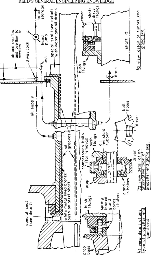
A minimum bearing length of two times the shaft diameter will ensure that the bearing load does not exceed 0.8 N/mm² (116 lbf/in²). That is half the length of the traditional water-lubricated bearing, and the reason is the load-carrying capacity of the white metal rather than the length of the bush.
A typical analysis of the white metal would be 3 per cent copper, 7.5 per cent antimony, and the remainder tin.
White metal thicknesses vary according to the classification society. Figures of 3.8 mm for a shaft of 300 mm diameter, to 7.4 mm for a 900 mm diameter shaft, have been quoted, with bearing clearances of 0.51 to 0.63 mm and 1.53 to 1.89 mm respectively.
Those two pairs of figures are worth remembering together, because they scale with the shaft:
| Shaft diameter | White metal thickness | Bearing clearance |
|---|---|---|
| 300 mm | 3.8 mm | 0.51 – 0.63 mm |
| 900 mm | 7.4 mm | 1.53 – 1.89 mm |
The weardown limit is far tighter than on a water-lubricated bearing. Weardown of the white metal should not normally exceed 2 mm, to avoid hammering out, and the period between inspections is about six years.
The reason for the tight limit is the load: white metal at 0.8 N/mm² is working hard, and once the clearance has opened up the shaft begins to hammer on the bearing rather than ride on the oil film. Hammering out is a progressive failure — once it starts it accelerates.
A highly resilient reinforced plastic material is often used in place of white metal. It is claimed to have superior load-carrying capacity, high resistance to fatigue and shock loading, and good lubrication properties.
4. The lip seals and the temperature limit
Oil is contained within the Simplex type stern tube by lip seals. The elastic lip of each nitrile rubber seal grips a rubbing surface provided by short chrome steel liners at the outboard and inboard ends of the steel propeller shaft. The outboard liner additionally protects the steel shaft from sea water contact and corrosion.
Heat produced by friction will result in hardening and loss of elasticity of the rubber, should the temperature of the seal material exceed 110 °C.
That single figure governs the whole cooling arrangement of the tube:
- Cooling at the outboard end is provided by the sea — the outboard seal sits in the water and loses its heat directly.
- Inboard seals, unlike those at the outboard end, cannot dissipate heat to the surrounding water. Oil circulation, aided by convection, is arranged to maintain a low temperature of the seals at the inboard end. Connections for circulation are fitted top and bottom between the two inboard seals and the small local header tank.
So the inboard seal is the one that needs the circulation, and a blocked convection path between the two inboard seals and the header tank is a blocked path to a hardened seal. That is the first thing to check when an inboard seal starts to leak.
The seal detail — the ring construction, the garter springs, the floating ring design, and the materials — is in Chapter 10.
5. The liner grooving problem, and the two remedies
The chrome liners act as rubbing surfaces for the rubber lip seals, but grooving from frictional wear has been a problem.
The mechanism is the one in Chapter 6: a lip seal running continuously on one band of a liner will cut a groove in it, and once the groove is deep enough the lip no longer seals against it.
The difficulty has been overcome in two ways:
- by using a ceramic filler for the groove; or
- by using a distance piece to displace the seal and ring assembly axially, so that the lip runs on a fresh band of the liner.
Allowance must be made for the relative movement of shaft and stern tube due to differential expansion when either remedy is applied, because the axial position of the seal relative to the liner is not fixed.
New seals are fitted by cutting and vulcanizing in position. A lip seal is a continuous ring that has to be fitted over the shaft, and it is made good by cutting it, wrapping it round, and vulcanising the joint.
6. Oil pressure, header tanks and the aft peak
The static lubrication system, for vessels with moderate changes in draught, has header tanks placed two or three metres above the maximum load waterline. The small differential pressure ensures that water is excluded.
The cooling of simple stern tubes necessitates keeping the aft peak water level at least one metre above the stern tube.
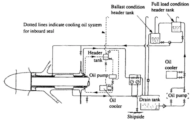
Tankers and other ships with large changes in draught may be fitted with two oil header tanks, for either the fully loaded or the ballast condition. Without the second tank, a ship whose draught varies by many metres would either be over-pressurising the tube when loaded or under-pressurising it in ballast — and under-pressurising it means sea water in.
The sketch also shows a circulation and cooling system for the inboard seals, which, unlike those at the outboard end, cannot dissipate heat to the surrounding water. This circulation may be obtained by natural convection.
Water in the aft peak has a cooling action on stern tubes which are oil lubricated, so the aft peak level matters twice over: it cools the tube, and it provides the sea pressure that the header tank has to beat.
7. Hydrodynamic and hydrostatic lubrication
The requirement for steaming at a slow, economical speed during periods of high fuel prices, or for other reasons, gives a lower fluid film or hydrodynamic pressure in stern tubes, because of the slower shaft speed. The possibility of bearing damage occurring prompted the installation of forced lubrication systems.
The supplied oil pressure gives adequate lift to separate shaft and bearing, and an adequate oil flow for cooling.
The distinction is worth holding on to:
| Hydrodynamic | Hydrostatic | |
|---|---|---|
| Where the pressure comes from | The rotation of the shaft, dragging oil into the wedge | A pump |
| Depends on shaft speed? | Yes — the film thins as speed falls | No — the lift is there at any speed |
| Fitted when | Normal service | Slow steaming, and where a low-speed film would otherwise be inadequate |
The design detail of a single-bush bearing with a forced lubrication system is shown in the same figure as the header tank arrangement. The pump pressure is what carries the shaft at low revolutions; the hydrodynamic film adds to it as the speed comes up.
8. Weardown, inspection and what the watchkeeper does
The weardown limits for an oil-lubricated tube are much tighter than for a water-lubricated one:
| Item | Figure |
|---|---|
| White metal weardown, normal limit | 2 mm |
| Period between inspections | about 6 years |
| Bearing clearance at 300 mm shaft | 0.51 – 0.63 mm |
| Bearing clearance at 900 mm shaft | 1.53 – 1.89 mm |
| Seal material temperature limit | 110 °C |
| Bearing load at 2 × shaft diameter length | not more than 0.8 N/mm² |
The in-service checks are:
- Header tank level, at every round. A falling level is a leaking outboard seal, and it is the earliest warning there is. A rising level, or a level that will not hold, may be sea water coming in.
- Oil condition. The oil should be checked for water. Sea water in the oil means the outboard seal is passing, and it will destroy the white metal.
- Stern tube oil temperature, in and out of the tube. A rising temperature with the oil clean is a bearing or a cooling problem; a rising temperature with water in the oil is a seal problem.
- Aft peak water level, kept at least one metre above the stern tube.
- The inboard seal circulating connections, top and bottom between the two inboard seals and the header tank, clear and open.
The seal material is nitrile rubber in the Simplex design. Fluor rubber, Viton, with additives has been shown to be more effective than nitrile butadiene rubber for seal rings, and ceramic coated liners can also be used — both are answers to the same problem, which is that the seal is the part that fails.