
The Propeller Shaft — Liners and Propeller Mounting
The propeller shaft is the part of the line that is under water, carries the propeller, and has to be protected against the sea and against the propeller's own weight.
Key Principles at a Glance 5 points
- The tailshaft carries the torque, carries the propeller's weight as an overhanging load, and passes through the stern tube — it is the most heavily loaded and least accessible shaft in the ship.
- Sea water is an electrolyte, so a water-lubricated shaft is protected by a shrunk-on bronze liner with a rubber seal between the liner end and the propeller hub; an oil-lubricated shaft needs only short chrome steel liners at the seal positions.
- A keyless propeller relies entirely on the interference fit: Lloyds require grip enough to transmit 2.7 times the nominal torque at 35 °C, and a bore stress at 0 °C not exceeding 60 per cent of the 0.2 per cent proof stress.
- The Pilgrim nut achieves the push-up by inflating an internal nitrile rubber tube against a steel loading ring, with the hub and shaft temperatures used to find the pressure from the maker's table.
- Oil injection reduces the coefficient of friction to about 0.015 while the oil is between the surfaces and leaves at least 0.12 when it is released — and that change is the whole method.
1. What the propeller shaft has to do
A keyless propeller is held on by interference alone, and the interference is the whole joint. The push-up is calculated, the temperatures are recorded, the figure is taken from the maker's table, and the push-up achieved is measured against two reference marks and written down. A propeller that has been "made tight" is a propeller that will come off.
The propeller shaft, also called the tailshaft, is the last length of shafting. It:
- carries the torque out to the propeller;
- carries the propeller's weight as an overhanging load, which bends it (the bending calculation is in Chapter 1); and
- passes through the stern tube, where it is supported by the stern bearing and protected from the sea by the seals at either end.
It is the most heavily loaded and least accessible shaft in the ship, and it is sized with a factor of safety of over 12 because the loading is fluctuating, indeterminate and corrosive all at once.
Two features follow from the duty:
- the after end is where the propeller is mounted — on a taper with a key, on a taper without a key, or on a flange;
- the whole of the shaft that is inside the stern tube is protected, by a liner in a water-lubricated installation, or by chrome steel liners at the seal positions in an oil-lubricated one.
The propeller shaft is withdrawn for examination at intervals set by the class rules. The intervals, the defects looked for, and the way the propeller comes off are in Chapter 6.
2. The bronze liner
Sea water is an electrolyte and will support galvanic corrosion. In a sea-water-lubricated stern tube the shaft is wet for its whole length inside the tube, and the steel of the shaft would waste away against the bronze of the propeller hub and the bearing.
Wastage of the vulnerable steel shaft is prevented by a shrunk-on bronze liner and a rubber seal sandwiched between the propeller hub and the liner end. The liner covers the shaft from the propeller hub forward through the bearing, and the rubber seal closes the gap between the after end of the liner and the face of the hub.
It is essential that the rubber has freedom to flow when nipped between the hub and the liner. The seal works by being compressed, and a seal that has nowhere to go when it is compressed will split or will hold the hub off its seating.
In oil-lubricated bearings the shaft does not require a full-length protective bronze sleeve, because the oil excludes the sea water. It does require short chrome steel liners at the seal positions, which are the rubbing surfaces for the lip seals and which also protect the steel from sea water at the outboard end.
The liner is a shaft component in its own right and has its own wear limits and repair rules. Those are in Chapter 6, section 6.
3. Keyed propellers
Traditionally, fixed pitch propellers have been fitted to the tailshaft with a key and taper, being forced on to the taper by the tightening of a nut.
For the conventional key and taper arrangement, keyways are milled in the shaft taper and the key is accommodated in the bore of the hub by slots machined through. Ideally the hub and shaft tapers would be accurately matched, and the hub would be stretched by being forced past the point of fit on the shaft taper by the propeller nut. The push-up of a few millimetres is calculated to give a good interference fit.
In the ideal condition the torque is transmitted totally by the interference fit, with the key being merely a back-up.
The key was intended as a safeguard either against poor fitting, or against reduced grip due to higher sea water temperature and differential expansion of the bronze hub and the steel shaft — bronze expands more than steel, so a hub that is tight in the dock can be less tight in warm water.
If conditions are not as intended, fatigue cracks can occur at the forward end of the keyway, and more serious fatigue cracks may result from fretting damage or corrosion, particularly in high-powered single screw ships.
The keyway is itself a weakening factor. A plain keyway milled in a shaft taper allows deformation of the surface when push-up is applied to the propeller, and where there is any transmission of torque from the shaft via the key to the propeller hub. Torque causes a deformation which tends to open the keyway, and the grip of the propeller along the side of the keyway does the same. The likelihood of cracking has been reduced by the employment of sled-type keys, radiused corners within the keyway, and spooning at the forward end — all of which are attempts to remove the sharp changes of section where a fatigue crack starts.
4. Keyless propellers — why they are used
Keyless fitting, where reliance is placed entirely on a good interference fit, has proved effective, and this method removes the problems associated with keyways and facilitates propeller mounting and removal.
The success of a keyless propeller depends on the accuracy of the hub and shaft tapers and correct grip from the stretched propeller hub on the shaft. Two things have to be satisfied at once:
- The degree of stretch, or strain, is controlled by push-up. It must ensure adequate grip despite any temperature changes and the consequent differential expansion of bronze hub and steel shaft.
- It must also avoid over-stressing the hub, and in particular any permanent deformation.
The class rules put figures on both requirements. Lloyds require that the degree of interference be such that the frictional force at the interface can transmit 2.7 times the nominal torque when the ambient temperature is 35 °C. And at 0 °C the stress at the propeller bore, as given by the Von Mises stress criterion, shall not exceed 60 per cent of the 0.2 per cent proof stress of the propeller material as measured on a test bar.
Those two figures are the whole design of the joint: enough grip when hot, not enough stress to yield when cold.
5. The Pilgrim nut method
The Pilgrim nut system, used with the shaft and bore surfaces dry and degreased — except for cast steel propellers, where wiping of the bore with an oil-soaked rag is recommended — achieves the correct push-up by a calculation based on the predictable friction of dry surfaces. The calculation gives the hydraulic pressure suitable for the prevailing ambient temperature to produce the required push-up.
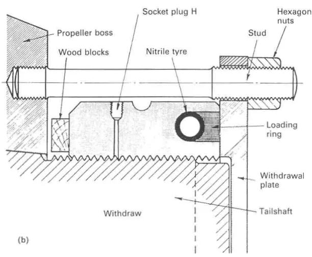
The Pilgrim nut has an internal nitrile rubber tube which, when inflated hydraulically, forces a steel loading ring against the hub. Two limits matter:
- Outward movement of the ring from the flush position must not exceed one third of the ring width, to avoid rupture of the rubber tube.
- The temperature of the hub and the shaft are recorded and used to find the correct final push-up pressure from the table provided in the instruction book.
The fitting sequence is:
- The propeller is checked against the mating surfaces with blue marker, and positioned.
- It is initially jacked on to the shaft taper before the Pilgrim nut is used.
- The Pilgrim nut is then used to apply an initial loading of perhaps 67 bar.
- A reference mark is made at this point, about 25 mm from the forward end of the hub.
- The nut is turned until the loading ring is again flush, venting hydraulic fluid, before full pressure is applied. During this stage the dial gauge should show the movement.
- A second mark is made 25 mm from the forward face of the hub.
- The push-up, registered by the distance between the two reference marks, is measured and noted.
- The nut is again vented and turned to bring the loading ring to the flush position, and finally nipped up with a tommy bar.
The Pilgrim nut can be reversed and used with a withdrawal plate and studs for removal of the propeller. To safeguard against any violent movement at release, wooden blocks are inserted as shown and a gap of only a little more than the push-up distance is left.
The Pilgrim keyless system owes its name to T. W. Bunyan.
6. The SKF oil injection method
The oil injection system of propeller mounting is associated with the name of SKF. With this method, instead of a dry push-up, oil is injected between the shaft taper and the bore of the propeller by means of high pressure pumps.
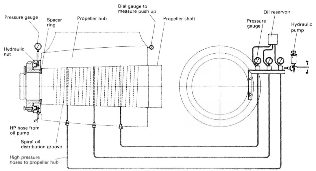
Oil penetration is assisted by a system of small axial and circumferential grooves, or a continuous helical groove, machined in the propeller bore. The oil reduces the coefficient of friction between the surfaces to about 0.015.
A hydraulic ring jack is arranged between the shaft nut and the after face of the propeller boss, and with this it is a simple matter to push the propeller up the shaft taper by the required amount, overcoming the friction force and the axial component of the radial pressure.
When the oil injection pressure is released, the oil is forced back from between the shaft and bore surfaces, leaving an interference fit with a coefficient of friction of at least 0.12.
That change from 0.015 to 0.12 is the whole method. While the oil is there the propeller can be slid up the taper with a modest jack; once it is gone, the same joint will carry the drive by friction with a large margin.
When it is required to remove the propeller, the process is equally simple and even quicker, with the injection of oil between the surfaces obviating the need for any form of heating or mechanical withdrawal equipment. Precautions are necessary to prevent the propeller jumping at release.
7. The cast iron sleeve
A development of the keyless method involves a cast iron sleeve which is bonded into the propeller boss with a special form of Araldite, injected under pressure.
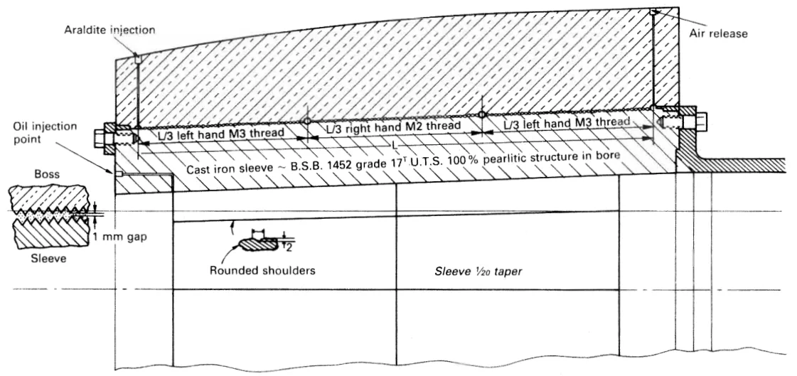
The sleeve is machined and bedded to the shaft taper, but can be used to adapt a general purpose spare propeller to a particular shaft taper. That is its main practical value — a spare propeller can be carried which will fit any of a class of shafts once the right sleeve has been bonded in.
The sleeve is easier to handle when machining and bedding than a complete propeller. A further benefit is that cast iron has a coefficient of friction nearer to that of the shaft than to the propeller bronze, so the friction across the joint is more predictable.
The drawing also shows the detail that makes the sleeve work: rounded shoulders rather than sharp corners, a 1 mm gap left at the end, and the threads — a left hand M3, a right hand M2 and a left hand M3 — arranged so that the sleeve is held and jacked by them.
8. Flange-mounted propellers
Many fixed propellers are flange mounted, being held by bolts. The propeller shaft is flanged at the after end and the hub of the propeller is bolted to the flange.
For these, outward removal of the tailshaft is made possible with the use of a muff coupling at the inboard end (Chapter 4) — because the flange on the shaft is no larger than the propeller, the whole assembly can pass through the stern tube once the propeller is off.
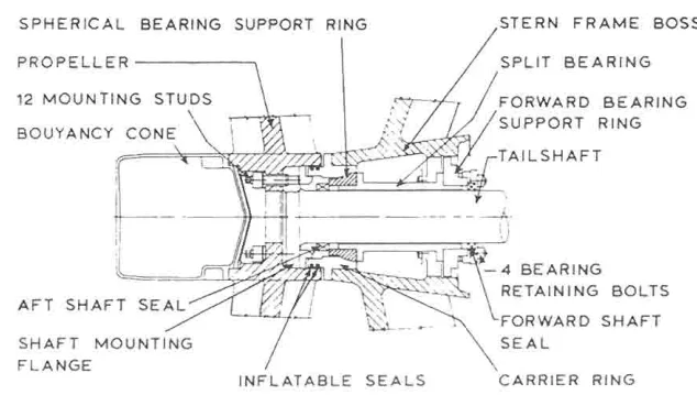
The flange mounting is what makes the split and withdrawable stern bearings of Chapter 9 possible. The propeller is held by studs on the flange, the stern bearing space can be sealed off by inflatable seals against the carrier ring, and the flange bolts can then be reached for inspection and crack detection without the propeller being taken off the shaft at all.
The Pilgrim hydraulic bolt is used in flange-mounted propellers as well as in flange couplings, for the same reason — it can be removed for inspection without being driven.