
Rudder, Stock and Carrier Bearing — Weardown, Rudder Drop and Pintle Clearance
The parts of the steering system that cannot be duplicated — the rudder, the rudder stock and the bearing that carries their weight — and the way their condition is measured.
Key Principles at a Glance 6 points
- Four measurements on this part of the system are worth watching, and each one says something different: rudder drop, jumping clearance, pintle bearing clearance and carrier bearing clearance.
- Rudder drop shows how much the carrier bearing has worn and at what rate; jumping clearance is a second, independent check on the same wear.
- Pintle bearing clearance shows wear in the lower bearing and whether the rudder is being supported as designed.
- Carrier bearing clearance is the thrust face and journal condition, measured directly when the rudder is lifted.
- A single measurement gives you a condition and a series of measurements gives you a trend — and the trend is what lets the work be planned into a docking rather than forced on the ship at sea.
- The alternative arrangement is the carrier bearing with a conical seat, and the weardown allowance is the figure that decides when the bearing has reached the end of its life.
1. The rudder and the rudder stock
The rudder and its bearings are surveyed against the class rules and the maker's limits, and the measurements are recorded. A weardown figure that is drifting towards its limit is a finding to be acted on, not a number to be noted.
The rudder is a flat plate hung behind the stern, and the rudder stock is the vertical shaft that turns it. The stock passes up through the hull into the steering gear compartment, and it is there that the tiller is keyed onto it and the steering gear gets hold of it.
The stock does two jobs at once, and it is worth separating them because they produce different stresses and different failures.
The stock carries the rudder's weight. A rudder is a heavy structure, and its weight hangs on the stock. That weight has to be transferred to the ship's structure, and it is transferred through the rudder carrier bearing at the top and, on some designs, through a pintle bearing at the bottom.
The stock carries the steering torque. The tiller turns the stock, and the stock twists the rudder against the resistance of the water. That is a torsional load, and it is what sets the stock's diameter.
The load path for the weight is: rudder → stock → carrier bearing thrust face → deck framing → hull. The load path for the torque is: ram → tiller → stock key → stock → rudder. The two paths meet in the stock itself, and the stock is sized for both.
Nothing about this can be duplicated. A ship has one rudder and one rudder stock. The equipment that operates the rudder can be duplicated and usually is; these two items and anything else that is not duplicated must therefore be of a strength sufficient to make failure unlikely. That is the rule, and it is the reason the stock is a heavy forging with a large margin, and the reason the tiller is keyed and shrunk on rather than bolted.
2. The rudder carrier bearing
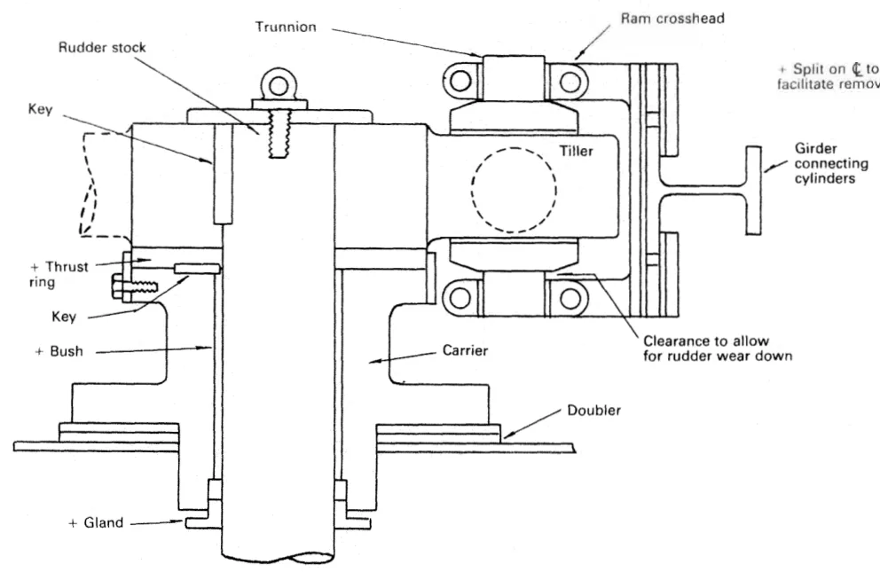
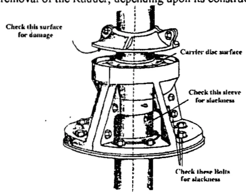
The rudder carrier bearing takes the weight of the rudder on a grease-lubricated thrust face. The rudder stock is located by the journal beneath, also grease lubricated.
Those two sentences describe two different duties performed by one assembly, and it is worth being clear which is which:
- The thrust face is the horizontal surface that carries the vertical load. It is a flat ring, and the rudder's whole weight presses down on it.
- The journal is the vertical surface beneath it that keeps the stock centred. It takes the side loads — the loads that would otherwise let the stock wander sideways in its bearing.
The thrust face is the part that wears, because it is carrying a large steady load and turning slowly under it. The journal wears much less, because the side loads are small by comparison.
How it is supported
Support for the bearing is provided by framing beneath the steering gear deck. The rudder's weight does not stop at the bearing — it has to be carried down into the ship's structure, and the structure under a carrier bearing is arranged for it.
There is thicker deck plating in the area beneath the carrier bearing, and the bearing may be supported on steel chocks. The base of the carrier bearing is located by side chocks welded to the deck. The side chocks do not carry weight; they stop the carrier moving sideways. The distinction matters when the bearing is being re-chocked: the chocks under the base take the load, the chocks at the side take the location.
Materials and construction
The carrier may be of meehanite with a gunmetal thrust ring and bush. Meehanite is a form of high-duty cast iron, and it is used for the body because it is strong, rigid and machinable. The gunmetal thrust ring and bush are the bearing surfaces themselves, and gunmetal is used there because it is a bearing material — it will run against a steel shaft with only grease between them, and it will wear in preference to the shaft.
Carrier bearing components are split as necessary for removal or replacement. A thrust ring in halves can be lifted out from around the stock without the stock being withdrawn, and a bush in halves can be renewed in the same way. This is what makes the bearing maintainable at all, given that the stock cannot be taken out of the ship without the rudder coming off.
Lubrication
Screw down (hand) lubricators may be fitted, but automatic lubricators are common. The screw-down lubricator is turned by hand to force grease into the bearing; the automatic lubricator does the same job continuously. Either way, the bearing is a grease bearing, not an oil bearing.
The grease used is of a water-resistant type — calcium soap base with graphite. Both parts of that specification matter:
- Calcium soap base makes the grease water resistant. The steering gear compartment is a damp place and the bearing is at the bottom of a well where water collects; a grease that emulsifies with water loses its lubricity and corrodes the bearing surfaces it was meant to protect.
- Graphite is a solid lubricant that keeps working when the grease film is squeezed out under the rudder's weight. On a thrust face carrying many tonnes and turning very slowly, the boundary lubrication provided by the graphite is what prevents metal-to-metal contact at the moment of starting to turn.
3. The alternative — the carrier bearing with a conical seat
An alternative type of carrier bearing has a conical seat, and it has the advantage that the seat and the side wall will locate the rudder stock. The angle of the conical seat is shallow, to prevent binding.
In the flat-seat design, the thrust face carries the weight and the journal provides the location, and those are two separate surfaces. In the conical design one conical surface does both: it carries the weight on the slope, and it centres the stock at the same time.
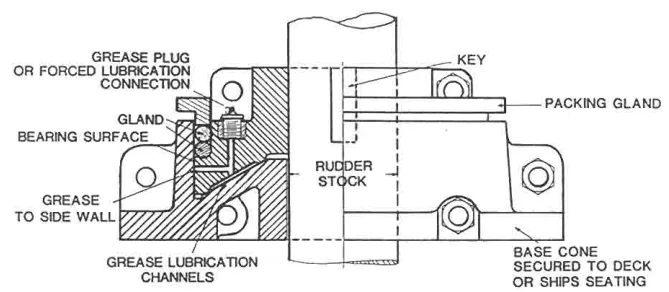
The shallow angle is the whole trick. A steep cone would wedge, and as the bearing wore down the stock would seat lower and lower with the load rising, until it seized. A shallow cone lets the stock settle with the load spreading sideways into the seat rather than wedging.
4. Weardown and the weardown allowance
The carrier bearing wears, and the wear is vertical. As the thrust face wears away, the rudder stock settles lower, and the rudder goes down with it.
Weardown of the carrier bearing is monitored by periodically measuring the clearance marked on the drawing. The original clearance is usually about 20 mm.
Bearing weardown occurs over a period of time, and allowance is made in the construction of the steering gear for a small vertical drop of the rudder stock. This weardown allowance is checked periodically and restored as necessary.
There are two numbers here and they are easy to confuse, so it is worth separating them clearly.
The design allowance is about 19 to 20 mm. It is built into the gear — there is clearance in the arrangement so that the stock can drop by that much before anything else is affected. It exists for a specific reason: the rudder's weight must be carried by the carrier bearing, not by the rams. If the stock drops far enough that the weight comes onto the rams, the rams are loaded in a direction they were never designed for, and they bend. That is the reason the allowance exists at all.
The working limit is much smaller — a rudder drop of 3 to 6 mm is the figure that matters in service. Long before the design allowance is used up, the drop is treated as a finding and the carrier bearing is attended to. The design allowance is the margin that must never be approached; the working limit is the figure at which work is done.
The clearance is restored as necessary. Restoring it means taking up the wear — renewing or reshimming the thrust ring so that the stock sits back at its correct height. It is a dry-dock job, and it is one of the items on the dry-dock overhaul list in Chapter 10.
5. Rudder drop and how it is measured
Rudder drop is the wear down of the rudder carrier bearing, and it is measured directly, not calculated.
It is measured by a trammel gauge. A trammel gauge is an L-shaped instrument. The method is a datum method, and it works like this:
- A point is marked on the hull inside the steering gear room — typically on the deck head girder above the stock.
- A second point is marked on the rudder stock.
- The distance between those two points is measured and recorded at the time of construction.
- The same distance is measured again at each survey.
- The difference between the original measurement and the present one is the rudder drop.
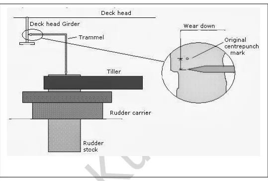
It is always measured in dry dock, because the measurement has to be repeatable and the ship has to be in a known condition for the readings to be comparable. The value of the method is that it compares like with like: the same two marks, the same gauge, the same ship, year after year. The trend is what tells you the rate of wear, and the rate is what tells you whether the bearing will last until the next docking.
If the allowance becomes zero, the weight of the rudder is transmitted directly to the rams, and the rams may be bent. This is the failure the whole weardown allowance exists to prevent, and it is why the allowance is checked rather than assumed.
If the drop is more than the allowance, maintenance of the rudder carrier bearing is required.
6. The jumping stopper
A rudder that can settle downwards can also be lifted upwards, and heavy weather does exactly that.
Lifting of the rudder and stock by heavy weather is limited by jumping stops between the upper surface of the rudder and the stern frame. The jumping stopper is a hard stop above the rudder that allows the rudder its normal small vertical movement and then blocks it. Without it, a sea getting under the rudder could lift the whole assembly and the shock would be taken by the steering gear instead of by the stern frame.
The jumping clearance is the gap at that stop, and it is a measurement in its own right.
| Condition | Jumping clearance |
|---|---|
| New ship | about 3 mm |
| Maximum allowable | about 6 mm |
It is measured with a thickness gauge. It can be checked during dry dock, and it can also be checked in the steering gear room using a chain block arrangement to lift the rudder and measure the gap.
An increase in the jumping clearance indicates that there is excessive bearing wear. This is the useful part: the jumping clearance is a second, independent measurement of the same wear that the rudder drop measures. If the rudder drop says the carrier bearing is wearing and the jumping clearance agrees, the finding is confirmed. If they disagree, something else is moving — a pintle bearing, or a loose component — and that is worth knowing.
7. The pintle bearings
Not every rudder hangs on its stock alone. Where the rudder is supported at the bottom as well, that support is the pintle bearing.
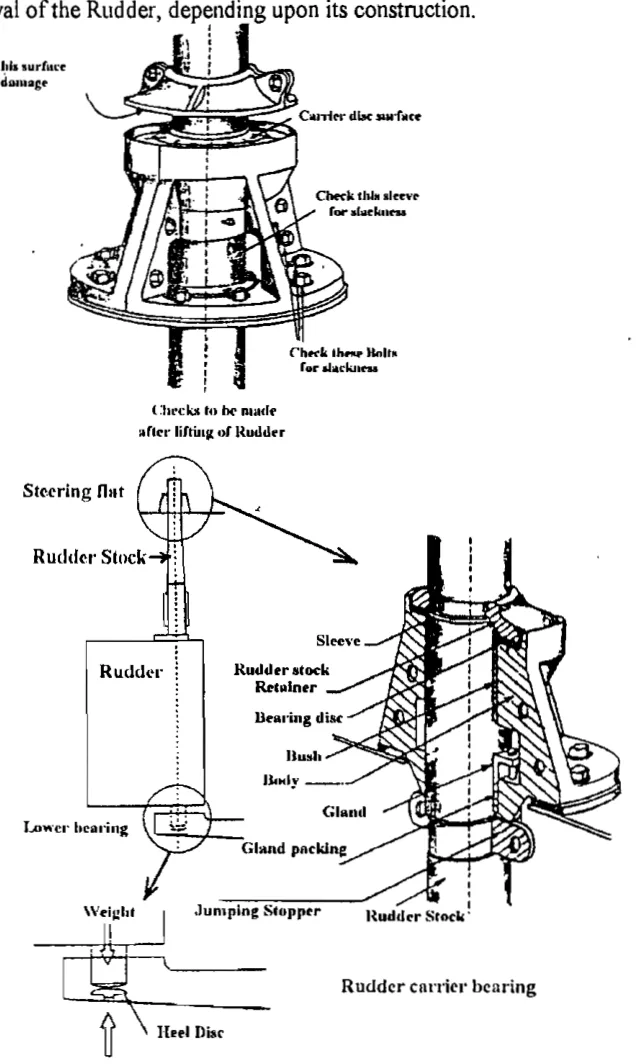
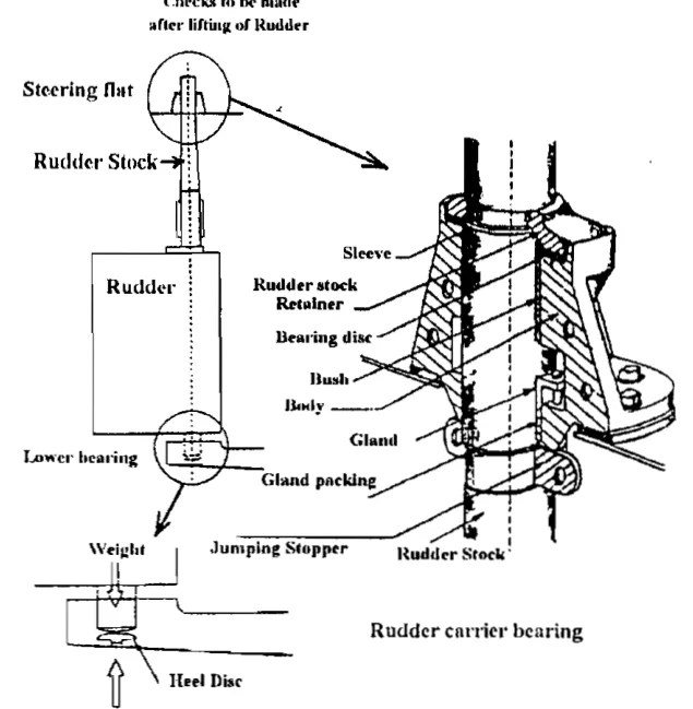
A pintle is a downward projection from the rudder that sits in a bearing on the stern frame, or an upward projection from the stern frame that sits in a bearing in the rudder, depending on the design. The arrangement used is what decides how the rudder has to be removed:
- A rudder with upper and lower pintle bearings must be lifted to get it off its bearings.
- A hanging rudder — one that hangs from the stock with no bottom support — is lowered.
- A Simplex type rudder has its rudder post removed instead.
The pintle carries part of the rudder's weight, which reduces the load on the carrier bearing, and it provides a lower pivot that steadies the rudder. Its bearing is a plain bearing with a defined clearance, and the clearance is measured and recorded at survey. The measurement procedure and the survey report form are in Chapter 10.
The components seen in a lifted rudder assembly are the weight sleeve, the rudder stock, the retainer, the bearing disc, the bush, the gland, the gland packing, the jumping stopper, the rudder carrier bearing and the heel disc. The heel disc is the bearing surface at the very bottom of the arrangement.
8. The limits of rudder movement
The rudder does not move through an unlimited angle, and there are three separate things that limit it.
The usual limit for movement of the rudder is 35° each way from the mid position, and this is controlled by the telemotor. The telemotor is what sets the working limit, because it is the telemotor's travel that stops the helmsman asking for more. The telemotor receiver's movement is limited by stops set at 35°.
External rudder stops, if fitted, would limit movement to about 39° from the mid position. These are mechanical stops on the rudder itself, and they are a backstop rather than a working limit — they are set wider than the telemotor so that in normal service they are never touched.
The steering gear itself will also impose a limit on rudder movement. The rams run out of travel, or the tiller reaches the end of its swing, and the gear stops moving.
The reason all three exist is the danger in the third one. With hydraulic oil loss and the ship stopped in heavy weather, there may be severe damage to the gear. If the gear is the thing that stops the rudder — rather than the telemotor, which the helmsman can feel and which stops the demand before the rudder reaches the end of its travel — then the gear is being driven hard against a hard stop, and the relief valves are the only thing taking the load. The telemotor control imposes the usual 35° limit, and keeping it doing so is a matter of maintaining the telemotor's stops rather than relying on the rudder stops.
On the vane type gear, the vanes themselves act as rudder stops, which is a different arrangement and is described in Chapter 6.
9. What the rudder and the carrier bearing tell you
Four measurements on this part of the system are worth watching, and each one says something different:
| Measurement | What it tells you |
|---|---|
| Rudder drop | How much the carrier bearing has worn, and at what rate |
| Jumping clearance | A second, independent check on the same wear |
| Pintle bearing clearance | Wear in the lower bearing, and whether the rudder is being supported as designed |
| Carrier bearing clearance | The thrust face and journal condition, measured directly when the rudder is lifted |
The pattern is the same as everywhere else on a ship: a single measurement gives you a condition, and a series of measurements gives you a trend. The trend is what lets the work be planned into a docking rather than forced on the ship at sea.