
The Propeller — Fixed Pitch, Controllable Pitch and Cavitation
The propeller is the machine that turns the engine's torque into thrust, and it is the only part of the plant that works in the sea.
Key Principles at a Glance 5 points
- A propeller drives the ship by giving a large mass of water a modest velocity aft, so a large slow-turning propeller is more efficient than a small fast one — which is why the engine and propeller are matched through reduction gearing.
- The blade is an aerofoil section developing lift in the flow, and blade twist exists because the speed of the blade through the water rises with radius while the inflow stays the same.
- Cavitation is where the local pressure on the back of a blade falls below the vapour pressure of the water, the bubbles collapse and remove metal — the defences are blade area, blade section and tip speed.
- The KaMeWa controllable pitch propeller uses a servomotor piston inside the hub, fed by a slide valve on a hollow rod through the shaft bore, so that the piston follows the valve and carries it back to neutral.
- A controllable pitch installation must have emergency local pitch control, communication and alarm systems, and a fail-safe navigable ahead pitch — none of the three is optional.
1. What the propeller has to do
A controllable pitch propeller is a hydraulic machine inside a rotating hub under water, and it is controlled by oil pressure through a box on a section of shaft inside the ship. The hub oil pressure and the oil level in the box are watched at every round, the fail-safe position is known before it is needed, and the pitch indication is treated as an instrument reading rather than as an opinion.
The propeller drives the ship by taking a large mass of water and giving it a modest velocity aft. That is the whole of it: thrust is the reaction to the momentum given to the water, and the art of the propeller is to move as much water as possible for as little wasted energy as possible.
The consequences of that are worth holding on to, because they explain the design:
- A large diameter propeller working in slow-turning water is more efficient than a small one working fast, which is why the propeller and the engine are matched through reduction gearing (Chapter 13) or by direct drive.
- The blade is a section like an aerofoil, developing lift in the flow, and it is the lift that produces the thrust.
- The whole blade cannot work at its best, because the speed of the blade through the water rises with radius while the inflow is the same, so the angle of attack has to change along the blade. That is what blade twist is for.
- The thrust has to be taken out of the water into the hull, which is done by the thrust block (Chapter 3), and the torque has to be carried out to the propeller by the shafting (Chapter 1 to Chapter 6).
2. The fixed pitch propeller, and its vocabulary
The fixed pitch propeller is cast in one piece and its blades cannot be moved. Almost all the words used about propellers come from it.
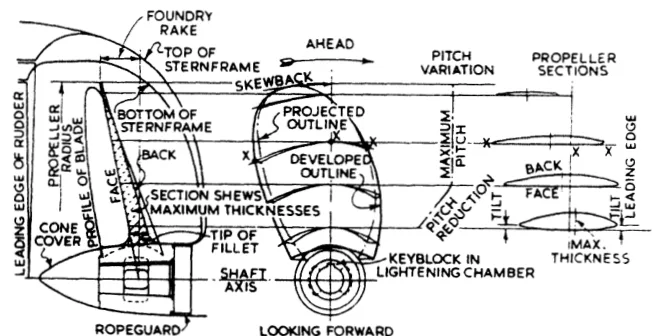
The words that matter in service:
| Term | What it is |
|---|---|
| Diameter | Twice the radius from the shaft centre to the tip. It sets the thrust, the torque and the tip speed. |
| Pitch | The distance the propeller would advance in one revolution if it were working in a solid nut — the theoretical advance, not the actual one. |
| Pitch ratio | Pitch divided by diameter. The usual way of describing a propeller's "coarseness". |
| Slip | The difference between the theoretical advance and the actual advance. Slip is not a fault; it is how a propeller develops thrust. |
| Developed area and blade area ratio | The blade area laid out flat, and that area as a fraction of the disc area. Blade area ratio is the main defence against cavitation. |
| Rake | The fore-and-aft angle of the blade, which sets the clearance between the blade tip and the hull. |
| Skew | The sweep of the blade back from the root, used to spread the load in time and reduce vibration. |
| Leading and trailing edge, face and back | The face is the pressure side, the back is the suction side, and the two edges are the ones that get damaged. |
| Tip fillet | The radius at the tip, which is where a crack would start if the tip were sharp. |
3. How a fixed pitch propeller is made
The normal method of manufacture for a fixed pitch propeller is to cast the blades integral with the boss, and after inspection and marking, to machine the tapered bore and faces of the boss before the blades are profiled by hand with reference to datum grooves cut in the surfaces, or with an electronically controlled profiling machine. Finally the blades are ground and polished to a smooth finish.
Each step has a reason:
- Casting the blades integral with the boss removes the joints, the studs and the extra thickness that a built-up propeller needs.
- Machining the tapered bore and faces first, before the blades are profiled, is what makes the fit on the shaft the datum for everything else.
- Datum grooves are the reference for the hand profiling, and the accuracy of the finished blade depends on them.
- Grinding and polishing to a smooth finish is not cosmetic. A rough blade surface promotes cavitation and costs efficiency, and a polished blade is also a blade that can be examined for cracks.
Built-up propellers, with blades cast separately and secured to the propeller boss by studs and nuts, were made obsolete as improvements permitted the production of larger one-piece castings. Their advantages were real — the ease of replacing damaged blades and the ability to adjust the pitch — but they were outweighed by the loss of efficiency resulting from restricted width at the blade root, the greater thickness required to maintain strength, and the larger hub diameter.
That trade-off is worth remembering, because the same argument is what makes the controllable pitch propeller expensive: putting the pitch mechanism in the hub means putting a large hub in the water.
4. Materials, cavitation and erosion
The blade has to be strong enough to carry the bending from the thrust and the centrifugal load of its own mass, and it has to survive in sea water. Those two requirements give the propeller its materials.
The common materials are manganese bronze for general work, nickel-aluminium bronze where the loading is higher and the corrosion resistance has to be better, and stainless steel for heavily loaded and ice-class propellers. The materials are chosen for a combination of strength, corrosion resistance, casting quality and repairability, and a propeller blade is a casting, so the casting quality is as much a part of the specification as the alloy.
Three failure modes to know:
Cavitation. Where the local pressure on the back of a blade falls below the vapour pressure of the water, the water boils locally and the bubbles collapse as they move into higher pressure. The collapse is violent and it removes metal, leaving a rough, pitted, sponge-like surface, usually on the back of the blade towards the tip. Once the surface is rough the cavitation gets worse. The defences are blade area, blade section and the tip speed — which is why a heavily loaded propeller has a large blade area ratio.
Erosion and corrosion. The face and the leading edge take the abrasion; the whole blade takes the corrosion. A polished, sound surface resists both, and a blade that has been left with a rough repair will do neither.
Cracking. Cracks start where there is a stress concentration — a sharp tip, a damaged edge, or a poor weld repair — and they propagate under the fluctuating bending load. This is why the tip fillet is a radius and why blade edges are examined at every drydocking.
The propeller is examined at the same time as the shaft (Chapter 6). Blade thickness is measured against the original, because a blade thins by erosion, and the thinning is what turns a repairable blade into a replacement one.
5. The propeller on its shaft
The propeller boss is the other half of the subject, and the boss has to carry the blade loads into the shaft without working loose, without cracking, and in a way that can be taken apart for survey.
Three arrangements are in use, and all three are described in Chapter 5:
- Key and taper, with the propeller forced up the taper by a nut and the key as a back-up to the interference fit;
- Keyless, either by a dry push-up with the Pilgrim nut or by oil injection, with the grip depending entirely on the interference;
- Flange mounted, with the boss bolted to a flange on the end of the propeller shaft, which is what makes the split and withdrawable stern bearings of Chapter 9 possible.
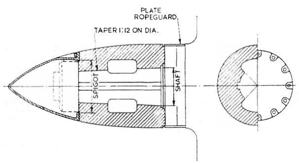
A flange mounted propeller carries an extra item: the propeller has its own self-contained bearing, and the drive torque shaft is more flexible in the alternative stern gear arrangement, where the bearing is inside the propeller boss itself. That arrangement is in Chapter 9, section 8.
6. The controllable pitch propeller
As its name implies, it is possible to alter the pitch of this type of propeller to change ship speed or to adjust to the prevailing resistance conditions. This change in pitch is effected by rotating the blades about their vertical axes, either by hydraulic or mechanical means.
The reasons for fitting one:
- A shaft generator can be driven at constant speed while allowing at the same time a change of ship's speed through the propeller. The engine runs at one speed for the alternator and the pitch does the manoeuvring.
- Since it is normally possible to reverse the pitch completely, this type of propeller is used with a unidirectional engine to give full ahead or astern thrust when manoeuvring. That is what makes it the natural partner of a gas turbine or a multi-diesel drive, neither of which can be reversed.
- The most obvious application is for ferries or other vessels which regularly and frequently manoeuvre in and out of port. A ferry does a large part of its engine running at manoeuvring pitch, and the ability to change pitch instead of changing engine revolutions and direction is worth a great deal.
- They are also used for double duty vessels, such as tugs or trawlers, where the operating conditions for towing or for running free are entirely different. A tug wants a fine pitch and high thrust when towing and a coarse pitch when running light, and one fixed propeller cannot do both well.
Controllable pitch propellers are normally fitted to a flanged tailshaft, because the operating mechanism is housed in the propeller boss.
7. The hub servomotor
One of the most widely used controllable pitch propellers is the KaMeWa, a hydraulically operated Swedish propeller first introduced in 1937.
In this unit the blade pitch is altered by a servomotor piston housed within the hub body. The piston moves in response to the difference in oil pressure on its ends.
The chain of operation:
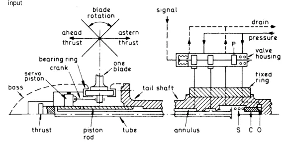
- Oil flow to and from the servomotor is controlled by a slide valve in the piston rod. The slide valve is part of a hollow rod which passes through a hole bored in the propeller shaft, and it is mechanically operated by operating levers located in an oil distribution box.
- If the slide valve is moved aft, the valve ports are so aligned that oil under pressure flows along the hollow valve rod to the forward end of the piston, causing the piston to move in the same direction, until the ports are again in a neutral position. When the valve is moved forward, the piston will move in a forward direction.
- When the piston moves, the crosshead with its sliding shoes moves with it. A pin on a crank pin ring, attached to each propeller blade, locates in each of the sliding shoes, so that any movement of the servomotor piston causes a pitch change simultaneously in the propeller blades.
The whole arrangement is therefore a follow-up system: the valve is moved, the piston follows it, and the piston carries the valve back to neutral as it goes. That is what makes the pitch hold where it is put.
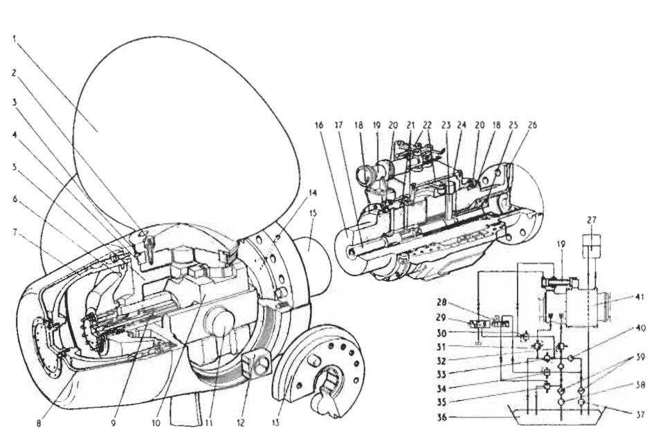
The blade is bolted to a flange rather than being cast with the hub, which is the price of making it movable: a blade sealing ring, a bearing ring and the blade stud with its nut and cover are all part of the assembly, and all of them are in the water.
8. The oil distribution box
The hub mechanism has to be fed with oil from a stationary ship into a shaft that is turning, and that is the job of the oil distribution box.
Oil enters and leaves the hub mechanism via an oil distribution box mounted inside the ship on a section of intermediate shaft.
The pressures and the pump:
- Oil pressure of about 40 bar maximum in the single piston hub is maintained by an electrically driven pump, which has a stand-by.
- A spring-loaded inlet pressure regulating valve on the oil distribution box controls the pressure in the high pressure chamber, from which the oil passes to the hub mechanism via the hollow rod in the propeller shaft.
- Oil passes from the hub mechanism to the low pressure chamber of the distribution box along the outside of the valve rod.
- A spring-loaded back pressure regulating valve on the oil outlet maintains a slight back pressure on the oil-filled hub when the vessel is under way. In port, this pressure is maintained by the static head of an oil tank mounted above the ship's waterline and connected to the oil distribution box.
- The oil pressure in the hub is needed to balance the outside pressure from the sea and so make leakage in either direction unlikely.
The control linkage:
The forward end of the valve rod connects to a T bar or key, which is moved forward or aft by a sliding ring within the oil distribution box. The T bar rotates with the shaft. A servomotor mounted externally to the box moves the sliding ring through a yoke. In the event of a failure in the servomotor, an external lever can be used to shift the valve rod manually and so control blade pitch.
That external lever is the emergency local pitch control, and its position is worth knowing on any ship that has one.
9. Pitch lock and fail-safe
A controllable pitch propeller has one failure mode that a fixed propeller does not have: the pitch can move on its own. Two arrangements deal with it.
The pitch lock. The central part of the tailshaft includes a shaft coupling and pitch lock. The pitch lock holds the blades where they are if the hydraulics fail, so that the propeller stays a propeller rather than going to flat pitch and losing all thrust.
The fail-safe spring. A powerful spring may be fitted so that, in the event of loss of hydraulic oil pressure, the blades will be moved towards the full ahead position. Two practical points attach to it:
- Forces on the blades tend to prevent the full ahead position from being attained, and it may be necessary to slow the engine, or even stop it, to allow the spring to act. A fail-safe that needs the engine slowed before it will work is a fail-safe the bridge has to be told about.
- The spring could be fitted to give a fail-safe to astern pitch instead, which is what a ship that has to be able to stop wants.
Some controllable pitch propellers are arranged to remain at the current setting if hydraulic oil loss occurs. That is the third possibility, and it is the one that depends entirely on the pitch lock.
Whatever is fitted, emergency local pitch control, communication and alarm systems, and a fail-safe navigable ahead pitch are required. Those are the three things a controllable pitch installation must have, and none of them is optional.
10. Control from the bridge
Two control philosophies are in use, and they are not interchangeable in the mind of the watchkeeper.
Where a shaft alternator is installed, engine speed may remain constant as propeller pitch is altered for manoeuvring. Speed and pitch are then separate controls, and the engine governor holds the frequency while the pitch does the work.
Alternatively, propeller pitch and engine speed can be remotely controlled from a single lever known as a combinator. Any number of combinators may be installed in a ship. The combinator lever controls pitch and speed through cam-operated transmitters, which may be electrical or pneumatic devices.
The combinator is what makes a controllable pitch ship drive like a fixed pitch one from the bridge: one lever ahead, one lever astern, and the cam shapes the relationship between pitch and speed so that neither the engine nor the propeller is overloaded at any point on the lever.
Engine room or bridge signal is fed to a torque-speed selector which fixes engine speed and propeller pitch, and feedbacks apply from each. The feedback is the point: without it, the pitch would be a command rather than a position.
11. What the engineer checks
On a controllable pitch installation, the items that matter at every round:
- Hub oil pressure. It is what balances the sea pressure at the seals and what holds the blades. A falling pressure is a leak, either at the box or at the hub.
- Oil level in the oil distribution box, and in the static head tank. The static tank maintains the hub pressure in port, when the pump is stopped.
- Oil condition. Water in the hub oil means a blade sealing ring or a shaft seal is passing, and sea water in the hub is a hydraulic system with a corrosion problem as well as a leak.
- Pitch indication against the bridge telegraph. A pitch that does not follow the lever is a valve or a feedback problem, and it will get worse.
- The stand-by pump, proved by starting it on a schedule rather than when it is needed.
- The emergency local control, with its position known and its lever free to move.
On a fixed pitch propeller the checks are the ones in Chapter 6: blade edges, tip fillets, blade thickness, and the condition of the rope guard that keeps rope away from the stern seal.