
Sea Water Lubricated Stern Tubes — Staves, Water Supply and Rewooding
The stern tube is the bearing at the after end of the shaft line, and the oldest way of lubricating it is with the sea.
Key Principles at a Glance 5 points
- The traditional stern bearing is lignum vitae staves held by bronze retaining strips in a gunmetal bush, with the lower staves cut end grain vertical for life and the upper ones cut axially for economy.
- The staves carry V or U grooves between them to let water through and to accommodate sand and grit rather than roll it between the stave and the shaft.
- Bearing length is four times the shaft diameter in the traditional design, and the clearances are liberal both for the swelling of the staves and to permit the essential flow of water through the bearing.
- The gland at the inboard end is set to pass a slight trickle into the tunnel well — a gland tightened until it is dry has stopped the circulation, and the bearing will not last the passage.
- The aft peak water level must be kept at least one metre above the stern tube, because the water in the aft peak is what takes the heat out of the tube.
1. What the stern tube is
A water-lubricated stern tube is lubricated by a supply of sea water, and the water has to be flowing. The gland is set to pass a slight trickle, the tunnel well is pumped regularly, and the water level in the aft peak is kept above the tube. A water-lubricated bearing with no water is a bearing with no lubrication, and it will not last the passage.
The propeller shaft is supported in a stern tube bearing of one of a number of designs.
The stern bearing is at the very end of the line, and it is the only bearing in the ship that carries the propeller's weight as an overhanging load. That load case — why the shaft droops, why the bearing is slope bored to suit it, and why the droop gets worse as the bearing wears — is worked through in Chapter 1, section 5. The point to carry into this chapter is the consequence: a stern tube bearing that has worn is worse than a bearing that has simply got a bigger clearance. It is a bearing that is being loaded on its edge, and it is no longer holding the shaft steady.
The whole of this chapter is about one of the two ways of dealing with that. The other way — enclosing the bearing in oil — is in Chapter 8.
2. The stave bearing
The traditional stern bearing is water-lubricated and consists of a number of lignum vitae staves held by bronze retaining strips in a gunmetal bush.
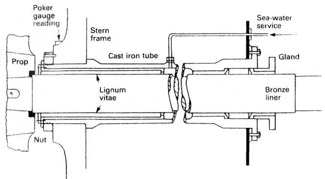
Lignum vitae is a hardwood with good wear characteristics and is compatible with water.
The staves in the lower part of the bearing are cut and fitted so that the end grain is vertical, to give the longest possible life. Staves in the upper part are cut with the grain in the axial direction, for economy — the top of a stern bearing does much less work, so the expensive cut is only used where it is needed.
The staves are shaped with V or U grooves between them at the surface, to allow access for water. The grooves also accommodate any debris — sand and grit that reaches the bearing is carried into the grooves rather than being rolled between the stave and the shaft.
They are held in place in the bronze bush by bronze keys, attached to the bush by countersunk screws.
Bearing length is equal to four times the shaft diameter in the traditional design. Modern designs are shorter.
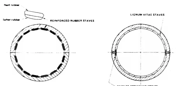
As an alternative to wood, reinforced rubber or Tufnol can be used.
3. The alternative stave materials
Some patent types utilise rubber bearing surfaces, but they are not generally used for the larger shaft sizes.
Impregnated plastic resin compounds on plastic bases have been used successfully in place of lignum vitae. One such type is called Tufnol.
Tufnol is a thermo-setting laminate produced from cotton fabric and phenolic resin as the main constituents. The fabric is impregnated with the resin, and the layers of this impregnated material are pressurised under heat until the fabric laminations are bonded into one sheet.
Its properties, and why they suit a stern bearing:
- uniform density, hardness and swelling, together with good wettability and a low coefficient of friction;
- an ultimate compressive strength, flatwise, approximately twice that of lignum vitae;
- a coefficient of friction of 0.005 when water lubricated;
- short length-to-diameter ratios with a greater continuous bearing surface can be designed at very high loadings with this material — which is why a Tufnol bearing is shorter than a lignum vitae one.
A water supply to the inboard end of the bearing is essential, and grease and oils should never be used with it. The staves are fitted with the V or U grooves as before, and the most preferred groove form is the UV type.
The swelling expansion due to water absorption is greatest in the direction normal to the laminate, and will not normally exceed 1 mm in 40 mm of thickness. The diametric clearance is about 2 mm for a 500 mm shaft — generous, to allow for that swelling and for the water flow.
Physical properties of a type suitable for tailshaft bearings:
| Property | Figure |
|---|---|
| Ultimate tensile strength | 62 MN/m² |
| Compressive stress (ultimate, flatwise) | 290 MN/m² |
| Shear strength (ultimate, flatwise) | 100 MN/m² |
| Young's modulus | 7 GN/m² |
| Impact value | 1.08 mN |
The material can be used for many other duties — general bearings, gears, resilient mountings and flexible couplings among them.
4. The tube and how it is held
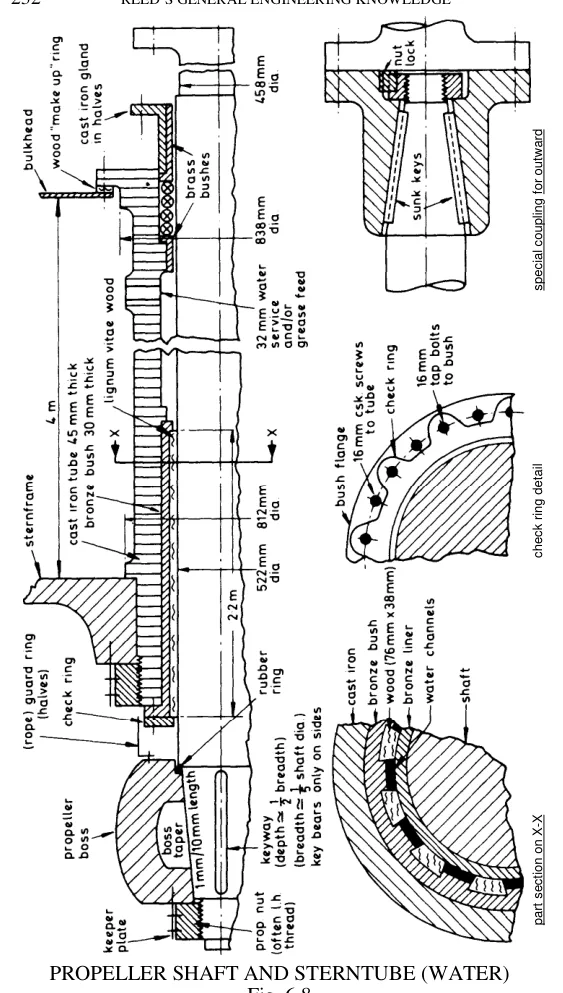
Stern tubes are supported at the after end by the stern frame boss and at the forward end in the aft peak bulkhead.
Their cast iron construction requires strong support in way of the bearing itself, from the stern frame boss. The tube is not stiff enough to carry the propeller load on its own; it is the boss that does it.
A steel nut at the outboard end retains the tube in position, with its collar hard against the stern frame and the bearing section firm within the stern frame boss. Welded studs hold the forward flange against the aft peak bulkhead.
A brass ring secured with set screws and sealed with white lead protects the outer screw thread from sea water. That is the detail that decides whether the tube can be drawn at the next drydock: an unprotected thread on a steel nut, in sea water, will be a thread that has to be burned off.
5. The water supply
The centre of the stern tube is connected to a sea water service line which, together with the ingress of water between the shaft and the bush, provides the cooling and lubrication.
Water enters at two places:
- at the after end, from the sea, between the shaft and the bush; and
- from the circulation system, through the sea water service connection into the centre of the tube.
A packed gland seals the forward end of the bearing and is adjusted to permit a slight trickle of water along the shaft and into the tunnel well, where it is regularly removed with the bilge pump.
The trickle is not a leak. It is the flow that proves the water is getting through the bearing, and it carries the heat and the grit out of the after end of the tube. A gland tightened until it is dry is a gland that has stopped the circulation.
Bearing clearances are liberal, both to accommodate the swelling which occurs when the staves are immersed in water and to permit the essential flow of water through the bearing. A tight water-lubricated bearing is not a better bearing; it is a bearing with no water in it.
6. Weardown and rewooding
Excessive weardown of bearing materials due to vibration or whirl, poor quality of work when rewooding, inferior materials, the presence of sand or sediment in the water, or propeller damage, could necessitate early rewooding.
The life of the bearing for vessels with engines aft, and particularly tankers and ore carriers which spend long periods in ballast, has been short, with rewooding being needed in perhaps eighteen months.
The reason those ships suffer is the one in Chapter 1: a ship in ballast floats high at the stern, the propeller is near the surface, the shaft line is at a different angle to the one it was aligned at, and the bearing is running with less water and more edge load than it was designed for.
A large number of vessels with water-lubricated bearings are still in service, and they continue to be installed — on the grounds of simplicity, because there is no oil to leak into the sea and no seal to fail inwards.
The weardown limits and the drydock measurement are in Chapter 6, section 3. The figures are in the region of 9 to 12 mm on large diameter shafts, or 8 mm where a continuous liner is fitted.
7. Sealing a water-lubricated tube
Radial face seals similar to those used for oil-lubricated stern tubes can be used for sea-water-lubricated stern tubes. These are fitted at the inboard end of the tube, with the outboard end open.
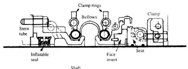
However, sea water is supplied from the sea water circulating system and runs out through the after end of the tube. The amount of any sand in the water would tend to be less after passing through the pipe system — which is one argument for feeding the bearing from the circulating system rather than relying on what comes in at the after end.
The detail of how these seals work, and of the three sealing arrangements used on stern bearings, is in Chapter 10.
8. The water-lubricated tube in service
What the watchkeeper does with one:
- Keep the water flowing. The sea water service valve to the stern tube is open, the gland is passing its trickle, and the flow is checked at every round on a new ship and after any work on the gland.
- Keep the tunnel well pumped. The tunnel well is where the trickle ends up. If the bilge pump cannot keep it down, either the gland has been over-slackened or something else has started leaking.
- Keep the aft peak water level above the tube. The cooling of simple stern tubes necessitates keeping the aft peak water level at least one metre above the stern tube. The water in the aft peak takes the heat out of the tube; a dry aft peak is an overheated bearing.
- Watch the bearing temperature. A rise in stern tube temperature with everything else normal means the water is not getting through, and the first thing to check is the gland setting.
- Record the weardown at every drydock, with the poker gauge, so that the rate of wear can be seen rather than only the present figure.