
Shaft Alignment — Datums, Sighting Methods and the Jacking Check
Alignment is the subject that ties the shaft line together.
Key Principles at a Glance 5 points
- Good alignment has only two objectives — that the bearings are correctly loaded and that the shaft is not severely stressed — and they pull against each other, so the line is a deliberate compromise.
- An alignment figure is meaningless without the condition it was taken in: the hull of a moderately sized ship can flex 150 mm in heavy weather, and a refrigerated ship's hull can contract 20 mm relative to the shaft.
- The reference line is set out from two small holes drilled at the correct height above the keel, one in the stern frame flange and one at the forward machinery space bulkhead.
- Sighting by light gives about 1 mm per 10 m, while the optical telescope with a target gives ±2 μm per metre — three orders of magnitude better, which is why the telescope is used for the checks.
- The jacking check measures the load each bearing actually carries, with a usual permitted deviation of plus or minus 50 per cent from the designed figure, and the shape of the lift against load plot is the diagnosis.
1. What alignment is for
An alignment figure is meaningless without the condition it was taken in. Bearing heights, coupling gap readings and jacking plots are all quoted for a stated draught, a stated load and a stated hull temperature, and a set of readings taken in any other condition is not comparable with them. Do not chase an alignment number; record the condition it was taken in and compare like with like.
Shaft systems would ideally be installed with straight alignment and remain in that state during ship operation. In practice there are many factors which affect and alter alignment during building and throughout the life of the vessel.
The intention of good alignment is to ensure that bearings are correctly loaded and that the shaft is not severely stressed. Those are the only two objectives, and they pull against each other. A line of bearings set dead straight in a light ship will not be straight when the ship is loaded, and a line set to be correct when loaded may be far from straight on the building berth. Alignment is therefore a compromise, and the compromise is chosen deliberately.
A bearing that is loaded too lightly is as much a problem as one loaded too heavily. A tunnel bearing carrying almost nothing lets the shaft move within it, which is a route to whirl; a bearing carrying far more than its share runs hot. The whole of this chapter is about measuring and controlling the share each one takes.
2. What changes the alignment
The list of things that move the shaft relative to the hull is long, and every one of them has to be allowed for in the design of the line.
Hull flexure with the load condition. The shaft line is continually changed through the lifetime of a ship by hull flexure from different conditions of loading — cargo, ballast, fuel, fresh water. The hull of a moderately sized ship can flex 150 mm in heavy weather. That is a movement of the hull of a third of a metre between one sea passage and the next, and the shaft line goes with it.
Differential expansion. High deck and low sea temperature in the tropics cause differential expansion and hogging. The deck is heated by the sun and the bottom is cooled by the sea, the hull takes up a hog, and the shaft line follows. In a midship-engined refrigerated cargo ship the low hull temperature can cause a contraction of the hull relative to the shaft of perhaps 20 mm.
Heavy weather, which produces changing conditions on top of the loading change.
The local factors at each bearing, which are the ones the engineer can actually see:
- forward tilt of the thrust block, as the thrust load tends to tip the block forward and lift its aft journal;
- shaft lift as fluid film pressure builds up in the bearings — the shaft does not sit in the bottom of a running bearing, it rides up on its own oil film, and it does so by an amount that varies with speed and load;
- sink of individual plummer blocks, as their chocks settle or their foundations work.
Propeller weight. The overhanging propeller pulls the after end of the shaft down and tilts the forward part up, which is what the slope-bored stern bearing is for (Chapter 1, section 5, and Chapter 7, section 1). This is not an alignment error; it is a permanent load case that the alignment has to accommodate.
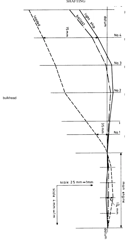
The practical conclusion is that the line moves by more than the tolerance the yard is working to, which is why the modern method accepts the movement and designs for the middle of the band.
3. The reference datums
Before any of the measuring methods can be used, the ship needs a line to measure from, and on a new ship that line is set out from the drawings.
The reference datums are the height of the shaft above the keel aft, and the height of the crankshaft centre above the keel extended to the forward machinery space bulkhead, also on the centreline athwartships. Both are taken from the ship's drawings, not measured from the ship.
The rough bore of the stern frame is fitted with a plate flange, and this flange has a small hole — say 1 mm — drilled at the correct height above the keel. With this centre the reference circle can be drawn for the setting up of the exact boring of the frame. In the same way, at the engine room forward bulkhead a small flange has a small hole drilled at the correct engine height above the keel and on the midships line.
Those two small holes are the whole basis of the alignment of the ship. Everything else is measured from the line of sight between them.
Optical or laser equipment can be used to establish the centre line in the same way, and to do more with it: a telescope with crosswires is set up on the shaft centre line at the forward end of the double bottom engine platform, with a plain crosswire target on the same axis at the after end of the engine seating. With both in use, the centre of the engine room and aft peak bulkheads can be located and marked prior to cutting holes for the shaft. The centre of the aperture in the stern frame boss is then found by line of sight, using a crosswire in an adjustable spider, and replacing the crosswire by a plug with a centre gives a location for the divider to be used when marking off the boss for boring.
The same equipment stays in use after the boring. The telescope and crosswire target method can also be used to check the accuracy of the boring operation, and the work on the installation of the stern tube and the siting of shaft bearings. Where the boss has to be welded in, as with a split stern tube, this operation can be guided by constant checking with optical equipment.
Deviation while building is a real cause of misalignment. The stern tube aperture can be incorrectly machined, due to flexure of the boring bar or to human error. Any contraction or expansion of the hull as a result of temperature variation can conspire with changes caused by welding of the hull to effect a change of hull shape. And the welding in place of a fabricated stern tube requires constant checks to ensure that alignment is maintained. Some stern tube bearing failures have been traced to alignment errors which should have been detected and remedied during installation.
4. Sighting by light
The oldest method is also the one that sets the reference line in the first place.
An electric light is sighted behind the hole in the forward machinery space bulkhead, and by looking from outside the stern frame the light can be seen through the two sight holes.
At the aft peak bulkhead, the aft machinery space bulkhead, and any watertight bulkhead through which the shaft passes, sighting plates are used. At each of those points:
- The horizontal plate is moved vertically up until the light line of sight is masked, and a horizontal reference mark is made across the bulkhead.
- The plate is moved vertically down until the light is masked, and another horizontal reference mark is made.
- Bisection of these two lines gives the horizontal centre.
The same procedure is then repeated using vertical boards moved horizontally port to starboard, and the bisection of those two lines gives the vertical centre.
Rough bores are then bridged, the centre is fixed temporarily with a tin plate and a small hole is centred, and from aft to forward a continuous light should be visible through all the bulkheads. The reference circles can now be drawn for exact boring.
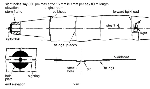
The accuracy of the method is worth knowing, because it is what decides whether the line is good enough: sight holes of say 800 μm, giving a maximum error of about 16 mm — that is, about 1 mm per 10 m of length. That is a setting-out accuracy, not a final alignment accuracy, and it is why the exact borings are checked afterwards by telescope.
5. Sighting by the optical telescope
Older alignment methods used piano wires and micrometers, and feelers between coupling faces, whereas modern methods utilise optical telescopes and targets giving accuracies of ±2 μm per 1 m of length. That is an improvement of three orders of magnitude on the light method, and it is why the telescope is used for the checks.
The equipment:
- The optical telescope has an eyepiece with cross lines, a focus, and vertical and horizontal micrometer adjustments, with a magnification of about 30 times. It is set up in a spherical mounting on a base with an adjustment bracket.
- The assembly is mounted on a spigoted plate and bolted into the aft end of the stern frame, being an exact fit.
- The target has circular, vertical and horizontal markings, and is fitted into an adjustable spherical mounting with a light. It is fitted to a flange bracket and set at the correct height and athwartships position on the forward machinery space bulkhead.
The method:
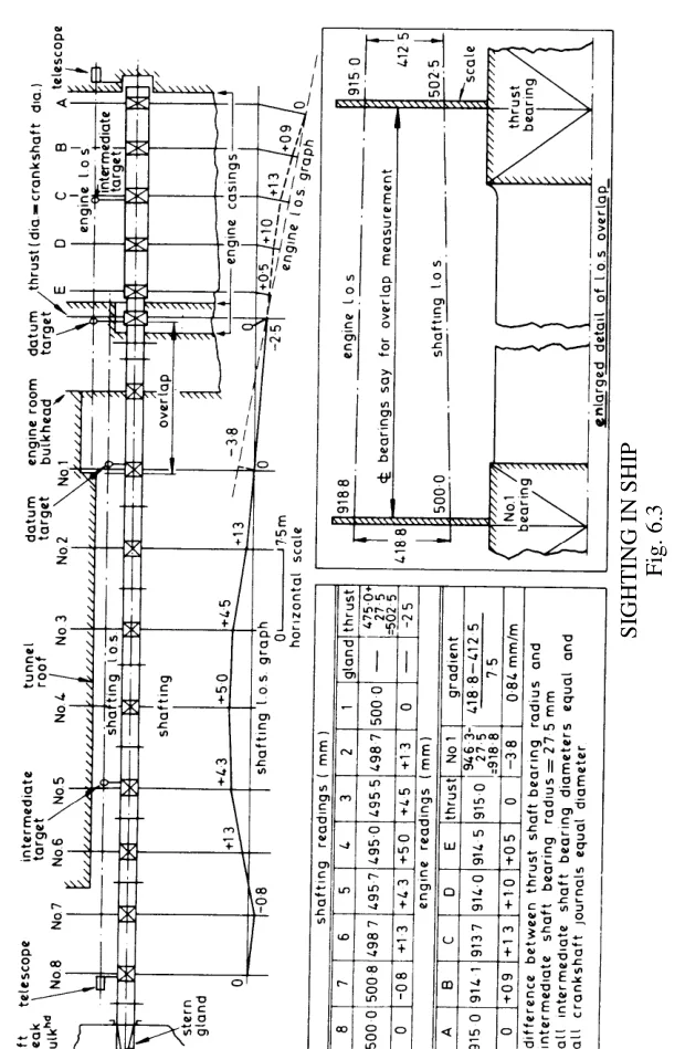
- The telescope is adjusted vertically and horizontally until the target is perfectly centred. This is the line of sight.
- Targets are fitted into adaptor plates and placed with a tight fit into all the intermediate bores.
- The telescope is focused on each in turn, giving any vertical or horizontal error.
- The telescope should be refocused on to the line of sight datum after each intermediate bore is checked.
Mirror targets can be used if it is thought desirable to check squareness. The result is a check on the initial lining up which should indicate a close degree of accuracy.
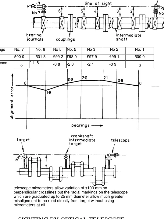
Once the ship is afloat and the intermediate shafting is fitted, the method changes slightly: the line of sight for telescope and target is fixed at the extreme ends, positioned at equal distances from the two journal diameters by cups mounted on matched stands which are in blocks strapped to the shaft. The target is usually mounted on the first bearing in the tunnel and the telescope on the last bearing before the tail end shaft. Readings are then taken for all the intermediate bearings by focusing on a lighted graduated scale held vertically on each bearing in turn, and a graph is plotted of any misalignment, with the chocking adjusted until a true line is effected.
It is also advisable to check all journal diameters for equality, and to take a horizontal alignment to ensure the correct port and starboard line. A shaft line can be perfect in elevation and out of line athwartships, and the athwartships line is the one that gets forgotten.
6. The older methods — the piano wire, and fairing the couplings
Both of these predate the telescope, and both are still worth knowing because they are what a shipyard or a repair yard will fall back on.
The piano wire
The wire is the older alternative to the telescope, and it is still used.
The technique produces fairly accurate results, especially in a vibration-free situation. Two details have to be handled:
Wire sag. A taut wire is not straight; it sags under its own weight. The allowance for sag varies with wire diameter and tension, and an empirical formula is generally used. For a wire of 0.5 mm diameter at 200 N tension, an approximate expression is sag = L²/9.25, where sag is in mm and L, the half length of the wire, is in metres.
Access along the shaft. For crankshaft alignment with five-cylinder engines and above, using telescope or wire methods, it is usually necessary to remove one connecting rod to allow the sight, or the wire, to pass over the full shaft length. The alternative is to take readings with an overlap across two central main bearings, possibly at two different heights, and then adjust to a common datum.
A light method can be used in calibration. One pole of a battery is earthed and the other, in series with an indicator lamp, is connected to the dial indicator touch stylus. As the wire is earthed, the slightest touch of the stylus on the wire causes the indicator lamp to light — which gives a repeatable zero without having to see the contact.
Interpretation of the readings, and their variation with ship loading conditions, are as described for the telescope method.
Fairing the couplings
Traditionally, the fairing of couplings has been used to align shafts and to check the alignment of adjacent shaft sections. The fairing of couplings involves the insertion of feelers between a pair of couplings to check that they are parallel, and the use of a straight edge or a dial gauge to ensure that they are concentric.
The trap in the method is worth stating, because it is the reason the fair curve method exists:
Incorrect alignment can result if it is assumed that the shaft sections are rigid — particularly with the heavy shaft sections for engines of high power. Account must be taken of the slight droop due to elasticity and overhanging weight at each shaft flange. A length of shaft is a beam, and a beam that is supported at two points droops in the middle and tilts at its ends.
The natural deformation of shaft sections is taken into account with rational alignment programmes, and coupling conditions can be used to position shaft sections and to check alignment. For this procedure, pre-calculation is used to find the gap and sag that should exist between the couplings when the shaft alignment is correct.
That is the whole of the modern method in one sentence: the coupling gaps and sags are calculated first, and the readings taken afterwards are compared with the calculation. A set of coupling readings with no pre-calculated figures to compare them against is a set of numbers, not an alignment check.
7. The fair curve method
The fair curve method is the modern answer to the fact that the ship will not hold still.
The method of fair curve alignment, developed at the Boston Navy Yard in 1954 and refined by others, accepts the changes of line endured by the shaft system and seeks a compromise to suit the varying conditions.
How the compromise is arrived at:
- The initial calculation determines the load on each bearing, assuming all bearings to be in a straight line.
- The computer program then simulates the raising of each bearing through a range, and calculates for each small change the increase of its own load and the alteration in load on each of the other bearings.
- The process is then repeated with a simulation of the lowering of each bearing in turn, with the computer finding the resultant load changes on the bearing in question and the others.
- Influence numbers — in terms of load change for each height variation — are calculated by the exercise, for all bearings.
The data bank of influence numbers enables the effects of changes in alignment from hull flexure and local factors to be found. All of the variables described for a pre-fair-curve-alignment ship can be matched to find the best compromise for shaft installation.
The practical meaning is that the yard does not set the bearings in a straight line; it sets them to a calculated curve, chosen so that the band of conditions the ship will actually meet produces acceptable loads in all of them. That is why a shaft line that looks wrong on the drawing can be exactly right, and why no bearing height is altered without the influence numbers being worked out again.
8. The jacking check
Whatever the alignment was designed to be, the only way to know what the bearing loads actually are is to measure them, and that is done by jacking.
The method of jacking to assess correct bearing loads is used as a realistic means of ensuring that, statically, the shaft installation is satisfactory.
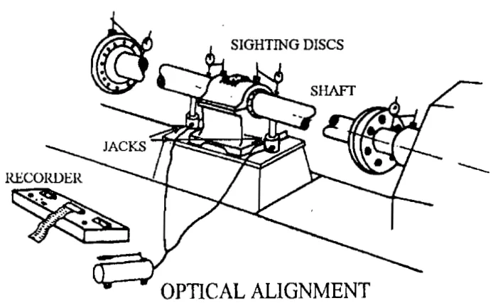
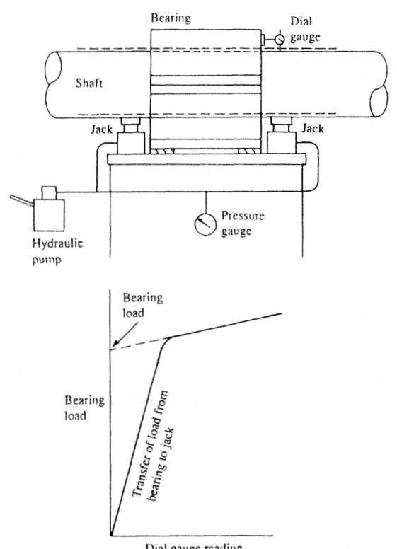
The procedure involves the use of hydraulic jacks placed on each side of the bearing, to lift the shaft just clear. A dial gauge fixed to the bearing indicates lift. Hydraulic pressure exerted by the jacks registers the load on the bearing. A plot of lift and load is made.
The figure to judge the result against: in simple terms, the load on each bearing can be stated as the total weight of the shaft divided by the number of bearings. The figure for designed load is normally given in a handbook, with the usual permitted deviation of plus or minus 50 per cent. The permitted variation may be less for some bearings. So a bearing well above or well below the average is not automatically wrong; it is wrong only if it is outside the band the handbook allows for that particular bearing.
The plot of lift against load has a distinctive shape, and the shape is the diagnosis:
- As the jack pressures are raised from zero, the concentrated loading initially causes deformation of the shaft. The dial gauges register upward movement as soon as the shaft is pushed out of shape, before the bearing is unloaded at all.
- Only after the journal section has been bowed up out of shape to some degree, and the bearing material resumes its relaxed primary shape, does the sagging centre part of the journal lift clear and out of contact with the bearing. That is where the curve changes slope.
- If the jacking is taken too far, adjacent bearings gradually become unloaded, and the plot is affected by a change in the elastic system. To guard against this, dial gauges are fixed on adjacent bearings to ensure that the lift is limited to the bearing that is being checked.
The last point is the one that makes a jacking check valid. Jacking one bearing until the shaft leaves it also lifts the shaft off its neighbours, and a plot taken without watching the neighbours is a plot of the wrong system.
Why the method is preferred over a simple measurement:
- Conventional methods of checking alignment give uncertain results unless the vessel is in the same condition with regard to loading and hull temperatures as when the shaft system was installed. Uneven bearing wear, hull deformation and the other factors in section 2 all affect the result.
- Jacking gives a direct measurement of load, and load is the thing that actually matters.
- It can be done afloat, in service, and repeated — so a bearing that has been losing its load over a period of years can be seen losing it, rather than only being found wrong when it fails.
The one thing the jacking check cannot do is tell you whether the alignment is right for a condition the ship is not in. It measures the ship as she floats at that moment, which is why the draught, load and hull temperature are recorded with the plot.
9. Alignment for different machinery arrangements
The problem is not the same for every installation, and three cases are worth knowing.
Aft-end installations. Such engined vessels do not suffer the same misalignment effects, because of the short rigid shaft length. There should be no need to line the engine down for load variations, the engine being lined exactly true, light ship, in the standard way. But the short stiff line has its own problem: the large tailshaft weardowns allowed — 8 mm and more — in, say, a 5 m shaft connected to the engine, throw a heavy load on the aft end of the crankshaft, and these vessels are somewhat more prone to tailshaft and aft end crankshaft failure. Two measures follow: very great care is advised in investigating the torsional vibration characteristics, and to offset the weardown load it is advisable to fit the tunnel and thrust bearings with fitted top halves and to limit weardown very strictly.
Even in a short shaft, alignment errors matter. Slew effects as much as 6 mm aft to 18 mm forward on the crankshaft, with the engine hogged vertically 3 mm, have occurred in the past.
Turbine-engined vessels. The alignment problem here is the gearing. In the past, alignment errors have commonly reflected back through the gearing to cause excessive pitting, scuffing and heavy wear on the second reduction pinions. Modern practice uses the optical telescope together with the pentagonal prism for line of sight deviation, which allows cross siting from a fixed reference plane — say the horizontal gearcase-to- turbine joint — to any number of points, including height checks of all the bearings. Three points are worth considering: the lift of the shafts due to the oil film should be taken into account; due to the high rotational speeds of the turbines there are precessional torque effects; and the flexible coupling copes with a considerable degree of misalignment.
Medium-speed engined ships with reduction gearing. The gearbox is the alignment-critical item, because the gear teeth are set by the relative positions of the pinion and wheel shafts, and the flexible coupling between the engine and the gearbox (Chapter 13) is what absorbs the misalignment the gears cannot.
10. What the watchkeeper sees
Alignment is not something the watchkeeper can measure, but it is something he can see going wrong, and the instrument is the bearing temperature.
An even temperature along the shaft line, at a steady load, is a line in alignment. What to watch:
- A bearing running hotter than its neighbours. That bearing is carrying more than its share. The first suspects are the local factors in section 2: a chock that has settled, or a foundation that has worked.
- A bearing that has been running hot and has cooled again at the same load. Something has moved — and a shaft that has moved is a shaft that has taken up a new line, not necessarily a better one.
- The stern tube temperature. The stern bearing is the one carrying the propeller load, and it is the one whose alignment is worst because of the droop (Chapter 7).
- Weardown at successive drydocks. The rate matters more than the figure (Chapter 6, sections 3 and 4). A weardown that has accelerated since the last docking is telling you the alignment has changed, not that the bearing material has suddenly got worse.
Two standing points:
Nothing on the shaft line is altered without recording it. No chock packed, no bearing lifted, no coupling broken, without writing down what was done and taking a fresh set of readings afterwards. The record is what makes the next set of readings worth anything.
A change of alignment is a change of load, and load is what fails bearings. The temperature is the symptom; the alignment is the disease.