
Propeller Shaft Faults, Weardown and Withdrawal
The propeller shaft is the one part of the shaft line that cannot be inspected while the ship is in service, and it is also the part that fails catastrophically when it does fail.
Key Principles at a Glance 5 points
- The defects found on a withdrawn shaft are keyway cracks, fretting under the forward end of the hub or the after end of the liner, erosion and cavitation patches on the liner, liner cracks, packing wear, rust cracking and thread damage.
- The two that lead to a broken shaft are fretting and corrosion at the hub–liner notch, where a leaking seal lets sea water in at the point of highest bending moment and a change of section.
- The propeller nut stays on the shaft thread until the propeller is proved free — accidents have been caused by propellers loosening with no nut in place to act as a stop.
- Weardown is measured by poker gauge: 9 to 12 mm is permissible on large diameter shafts in a water-lubricated bearing, or 8 mm maximum where a continuous liner is fitted.
- Propeller drop is a drydock measurement with a maximum allowance of only 0.2 to 0.3 mm, and the shaft is withdrawn every two years, or every five where a continuous liner, a stress-reduced keyway or a keyless fit qualifies.
1. What the examination is looking for
The propeller nut stays on the shaft thread until the propeller is free. Wedges are used to start a propeller, and a propeller that lets go under a wedge load will travel the length of the shaft. The nut is slackened but left in place, and it is only removed when the propeller is proved free.
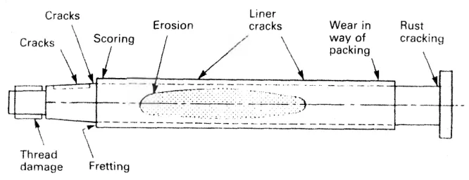
The list of defects is short and each one has a cause:
| Defect | Where | Cause |
|---|---|---|
| Cracks | Forward end of the keyway | Deformation of the keyway by push-up and by torque; sharp corners |
| Fretting | Beneath the forward end of the propeller hub, or under the after end of the liner | Relative micro-movement between the hub or liner and the shaft |
| Erosion and cavitation patches | On the bronze liner | Shaft whirl, and cavitation in the water around a whipping liner |
| Liner cracks | Through the shrunk-on bronze liner | Working conditions; may penetrate through to cause corrosion cracking in the shaft |
| Wear in way of the packing | On the shaft or liner where the stern gland packing runs | Scoring by the packing, and grit carried in it |
| Rust cracking | On the exposed steel | Corrosion of unprotected steel |
| Thread damage | The taper end and the propeller nut thread | Handling, and the propeller working on the nut |
The two that matter most are the ones that lead to a broken shaft:
Fretting and corrosion at the hub–liner notch. The rubber seal sandwiched between the propeller hub and the protective bronze liner prevents the ingress of sea water, which would act as an electrolyte to promote galvanic corrosion of the exposed part of the shaft. A defective seal permits corrosion and wastage. Fretting of the steel shaft tends to occur beneath the forward end of the propeller hub, or under the after end of the liner.
Any pitting or marking of the shaft surface in the area, or notch, between the propeller hub and the bronze liner can initiate a fatigue or corrosion fatigue crack in this vulnerable area. The geometry is against the shaft there: it is a change of section, it is where the bending moment from the propeller is highest, and it is where a leaking seal puts sea water.
The alternating stress is there all the time. Shaft droop from the overhanging weight of the propeller stretches the upper surface and compresses the lower, to produce alternating stress when the shaft is rotating. The imposed alternating effect likely to cause fatigue is of a low frequency and of high stress — a few hundred cycles an hour, at a stress level that would be harmless if it were steady.
The liner can itself be the source of the trouble. The shrunk-on bronze liner, fitted to protect the steel shaft against black corrosion, may itself be damaged by working conditions. Shaft whirl can lead to patches marked by cavitation erosion; scoring occurs in way of the stern gland packing; and liner cracking has sometimes penetrated through to cause corrosion cracking in the shaft.
2. Withdrawing the propeller
The examination of a keyed tailshaft in a sea-water-lubricated bearing requires removal of the propeller and inward withdrawal of the propeller shaft.
The operation calls for:
- the erection of staging at the after end;
- the use of a large, suspended ram or tup for the spanner, to slacken the propeller nut;
- wedges to start the propeller off its taper;
- the nut left on the thread after being slackened, for safety; and
- timber placed between the aft peak bulkhead and the flange at the forward end of the tailshaft, to support the shaft against the action of the wedges.
Accidents have been caused by the sudden loosening of propellers with no nut in place to act as a stop. That sentence is the whole of the safety case for leaving the nut on, and it is why the operating rule at the head of this chapter is written the way it is.
Keyless and oil-injection propellers come off far more easily, using the Pilgrim nut reversed with a withdrawal plate (Chapter 5), or by injecting oil between the taper and the bore (Chapter 5). Both methods still need the wood blocks or the gap limit that stops the propeller travelling when it releases.
3. Weardown, and the poker gauge
During drydock inspection, the bearing weardown is measured by poker gauge, or by inserting a wedge between the shaft and the bearing from the outside.
The poker gauge is a depth measuring instrument. A special access point is provided for it, generally bolted with a copper gasket, and the gasket is removed before the measurement is taken. The gauge is put through the access and the drop of the shaft is read directly.
The permissible weardown is in the region of 9 to 12 mm on large diameter shafts in a sea-water-lubricated bearing. Where the shaft has a continuous liner, the figure is more commonly set at 8 mm maximum, with the continuous liner examined every three years.
For an oil-lubricated white metal bearing the figures are much tighter, and they are in Chapter 8.
4. Propeller drop
Propeller drop is the drop of the propeller shaft due to the weardown of the stern tube bearings, and the weight of the propeller. The two causes act together, and the mechanism is worth following:
- The propeller shaft is fixed at one end and free at the other. The free end is loaded with the heavy propeller, which tends to bend the shaft down.
- The stern tube bearings support the shaft and prevent that bending.
- The liner and the seals are fitted over the liner, and the seals slowly cut grooves in the liner; after a time the sealing is lost.
- Sea water then enters the sealing areas, the lubrication is reduced, and because of the poor lubrication there is wear on the liner and on the stern tube bearing.
- The clearance increases, the weight of the propeller bends the shaft further, and the shaft goes down. That drop is the propeller drop.
The figures that go with it:
| Item | Figure |
|---|---|
| Normal bearing clearance | 0.5 to 0.6 mm |
| Clearance at which the stern tube bearings should be replaced | 0.9 mm |
| Maximum allowable propeller drop | 0.2 to 0.3 mm |
Propeller drop is measured with a poker gauge, at the special access point provided for it. Because the allowance is only 0.2 to 0.3 mm, the measurement is a fine one and the access point has to be clean and the gauge proved before the reading means anything.
Propeller drop is a drydock measurement, and it is the figure that decides whether the stern tube bearing comes out. It is also the figure that ties the shaft to the alignment in Chapter 11: a shaft that has dropped at the after end has had its whole line altered, not just its after bearing.
5. Liner wear and repair
The bronze liner has its own wear limits, and they are generous compared with the bearing clearances because the liner is a protective covering rather than a bearing surface.
Fissures in the liner should be machined down, provided that the liner thickness remains within the wear limits; otherwise the damaged part must be renewed. The maximum wear allowable is:
| Position | Maximum allowable wear |
|---|---|
| In way of the bearing area | 25 per cent of the rule thickness |
| In way of the stern gland | 50 per cent of the rule thickness |
These measurements are taken after machining of the corroded or rubbed areas of the liner. If the damage is severe the liner has to be replaced, and new liners must be hydraulically tested. Material checks are done as required by the class rules, and the liner is finally machined.
Workshop repair of a liner can also be done by replacing the damaged portion with two half shells, fitted on to the shaft and welded together longitudinally.
6. How often the shaft comes out
Propeller shafts are withdrawn for examination every two years, or every five years for shafts fitted with:
- continuous liners;
- oil-lubricated types with special stress-reduced keyways; or
- keyless shafts, or most controllable pitch propeller designs.
The two-year figure is the base case, and every one of the extensions is granted for a design feature that removes the keyway, or keeps the sea off the steel, or both. The interval is a class requirement and the extension is only available where the design qualifies.
For a withdrawable stern gear system the position is different, because the shaft can be examined without being drawn at all. That is the point of those systems, and it is covered in Chapter 9.
In the interval between withdrawals, the shaft is examined as far as it can be:
- by poker gauge for weardown, at every drydock;
- by the tailshaft being turned and the exposed length inspected, where a split stern bearing or a withdrawable system allows it;
- by crack detection of the propeller flange bolts, from outside, where the design allows the rope guard to be removed; and
- by the stern gland leakage and the seal condition, continuously, from inside the ship.
7. What the surveyor will ask for
A propeller shaft survey is one of the surveys where the paperwork and the hardware are checked together. Expect to be asked for:
- The recorded bearing clearances and the weardown measurements from previous surveys, so that the rate of wear can be seen and not just the present figure.
- The propeller push-up figure and the reference mark distances from the last mounting, from the record made when the propeller was fitted (Chapter 5).
- The class-approved welding and repair procedure for any liner repair, with the preheating, welding consumables and stress-relieving recorded.
- The material certificates for the shaft, the liner and the propeller.
- The crack detection records for the keyway, the taper and the flange bolts, with the method used.
- The seal replacement records, since a leaking seal is the start of most of the defects in section 1.
The defects in section 1 are nearly all of them traceable back to a seal that was allowed to leak, or to a keyway that was machined without radiused corners. Neither is a shaft problem; both show up on the shaft.