
Reduction Gearing, Flexible Couplings and Clutches
A medium-speed diesel does not turn at a propeller's speed, and the machinery that sits between the two is the reduction gearbox.
Key Principles at a Glance 5 points
- Reduction gearing exists because a medium-speed diesel wants 400 to 750 rev/min while a large propeller wants 80 to 150, and it also permits more than one engine to be coupled to the same propeller.
- The reverse/reduction gearbox reverses the propeller shaft without reversing the engine, so that continually starting on cold air is avoided and less compressed air capacity is required.
- Gear teeth are loaded by the pulses of torque from each firing stroke rather than by the mean torque, and a torsionally flexible coupling between the engine and the gearbox is what keeps those pulses out of the teeth.
- The Geislinger coupling connects its housing and hub with leaf springs; the spring packs are a wear item, and the coupling's stiffness changes as they wear, which changes the torsional characteristics of the line.
- The emergency driving plate makes the clutch solid so that the ship can reach port, but prolonged use can destroy the gearbox — one medium-speed engined ship needed a replacement after six months.
1. Why reduction gearing
Gear teeth are loaded by the pulses of torque coming out of the engine, not by the mean torque, and the flexible coupling is what keeps those pulses out of the teeth. No clutch is worked with a low air pressure alarm suppressed, and no gearbox is run with the emergency solid coupling engaged for longer than it takes to reach a port.
For medium-speed engine installations in large ships — as opposed to coasters or intermediate sized vessels — reduction gears are needed to permit engines and propellers to run at their best respective speeds.
That single sentence is the whole argument. A medium-speed diesel runs at something like 400 to 750 rev/min and a large propeller wants to run at perhaps 80 to 150 rev/min. Neither will do the other's job well:
- The propeller wants to turn slowly, because a slow-turning propeller of large diameter moves a large mass of water at a modest velocity and does so efficiently (Chapter 12, section 1).
- The engine wants to turn fast, because at a given power a faster engine is smaller and lighter.
Their use also permits more than one engine to be coupled to the same propeller. That is the second reason and, on a modern multi-engine installation, often the more important one: two or four medium-speed engines on one gearbox give a redundancy that a single slow-speed engine cannot, and they let the plant run at part load on one engine with the others shut down.
2. Selecting a gearbox
Gearboxes are available from manufacturers in standard sizes. Firms produce a standard range for different powers of single and multiple input, single reduction gearboxes for medium- or high-speed engines, in a number of frame sizes.
The input and output shafts for single input gears may be either horizontally offset, vertically offset or coaxially positioned. That choice is a layout decision, not a performance one: it is made to suit where the engine sits in the ship relative to where the shaft line has to run.
From the appropriate selection chart, using figures for engine power, engine speed and reduction ratio — also the classification society correction for ice if applicable — the size and weight of the appropriate gearbox can be found. The ice correction is worth noting: it is a class requirement, it changes the gearbox size for the same power, and it is a good example of how the operating environment of a ship is written into the machinery selection.
3. Twin screw arrangements
Ship manoeuvring is of course improved with twin screws, and this is an added safeguard against total loss of power due to engine breakdown.
The disposition of two engines and shafts can sometimes be improved with the use of offset gearboxes.
There is one convention that matters for manoeuvring:
Normally, twin screw propellers turn outward when running ahead. Viewed from astern, the port propeller turns anticlockwise and the starboard propeller turns clockwise.
Inward-turning propellers tend to make the movement of the stern unpredictable when manoeuvring, and have given rise to other problems. That is the reason for the convention, and it is worth knowing because a twin-screw ship that handles oddly at slow speed may be one that was built the other way round.
4. The reverse/reduction gearbox
Reversing with the use of a gearbox, after reducing engine speed as necessary, means that continually starting on cold air is avoided and less compressed air capacity is required. On a medium-speed engine the alternative to a reversing gearbox is to stop the engine and restart it on air in the opposite direction, which consumes starting air and puts thermal shock into the engine every time the ship manoeuvres. The gearbox takes that duty instead.
Reverse/reduction gearboxes, like straight reduction gears, are also obtainable in standard sizes, with manufacturers' charts for selection. Gear lubrication is by a self-contained system on many sets.
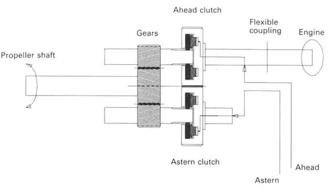
There are various arrangements possible for the shafts in a reverse/reduction gearbox, to suit the required location of the engine input or drive shaft and the driven or output shaft. The drawing shows a simplified, flat arrangement for ease of explanation.
How it works:
- The drive from the engine input shaft to the countershaft is through teeth on the outsides of both clutch housings, which are in continuous mesh. Both clutches therefore turn all the time; only one of them is driving.
- When the control lever is set for ahead running, the control valve supplies oil pressure to the ring piston of the ahead clutch. When the control lever is set for astern running, the control valve supplies oil pressure to the ring piston of the astern clutch.
- When either clutch is engaged, its pinion provides a drive to the large gear wheel of the driven shaft, and the other pinion rotates freely.
- Oil pressure required for clutch operation is built up by a gear pump driven from the input shaft. Lubrication is by means of overflow oil.
- The propeller thrust on the driven shaft is taken up by the thrust bearing. The gearbox carries its own thrust bearing, and it is the equivalent of the main thrust block (Chapter 3) for that arrangement.
Two rotations follow from the layout, and they are the ones a watchkeeper should be able to state:
- For ahead running, the driven or propeller shaft rotates in the opposite direction to the drive or input shaft.
- For astern running, the driven or propeller shaft rotates in the same direction as the drive shaft.
- To stop the propeller shaft, the control is moved to the neutral position and both clutches are disengaged.
5. The torsional problem the gearing creates
Putting gear teeth between an engine and a propeller creates a problem that neither has on its own.
Where a gearbox is fitted, a torsionally flexible coupling is necessary between the medium-speed diesel and the reduction gear. The reason:
The coupling is necessary because the periodic application and reduction of torque as engine cylinders fire in turn tends to result in alternate loading and unloading of the gear teeth. The torsional vibration effect is sufficient to cause serious gear tooth damage.
Every firing stroke puts a pulse of torque into the shaft, and between firing strokes the torque falls away (Chapter 1, section 8). At the gear teeth those pulses appear as the teeth being loaded and unloaded several times a revolution, which is a fatigue load applied directly to the tooth flanks. The flexible coupling sits between the engine and the first gear and absorbs the pulses before they reach the teeth.
Flexible couplings may be installed as separate entities, or in conjunction with air- or oil-operated clutches. Flexible couplings may be built in a common casing with the clutch.
Apart from protecting the gears, flexible couplings are also able to withstand slight misalignment — which is the second thing they do, and the reason they appear in the alignment discussion in Chapter 11, section 9.
6. The Geislinger coupling
The Geislinger coupling is the type shown in the source material and is a good example of a torsionally flexible coupling.
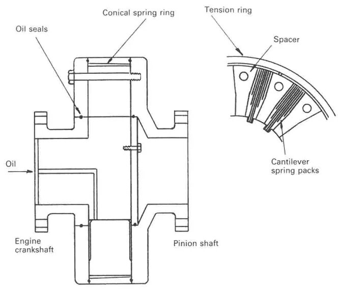
The Geislinger coupling has a housing and hub connected by leaf springs, which flex in service to absorb torsional effects from the engine.
The construction is worth noting for its maintenance implications: oil seals at each end keep the lubricant in and the dirt out, the cantilever spring packs are the working elements and are a wear item, and the spacer is what makes the coupling long enough to be worked on without moving the engine or the gearbox.
A flexible coupling is not a maintenance-free item. The springs fatigue, the seals harden, and the coupling's stiffness changes as the springs wear — which changes the torsional characteristics of the whole line.
7. Air-operated clutches in general
Clutches which are not part of the gearbox are usually air activated, with pads or linings which make either radial or axial contact.
The common features of both types:
- The application force for the friction pads or linings is supplied by compressed air in a reinforced neoprene rubber tube. The tube is the actuator and the seal at the same time, and it is the part that fails.
- The compressed air is filtered and moisture is removed by drains provided in the system. Water in the air is what perishes the rubber tube and freezes in the line in cold weather.
- Air pressure is monitored, and the low pressure alarm is particularly important. The transmission of torque relies on the air pressure, and loss of pressure would allow slip. A slipping clutch burns its linings and can destroy the gearbox behind it.
- Some form of rotary connection between the air supply pipe and the clutch is necessary, with the valve controlling the air supply to the clutch tube being operated by hand or remotely controlled by a solenoid or by air pressure.
8. The radial air clutch
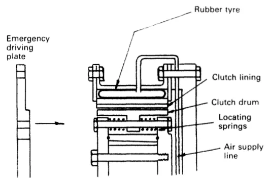
For a radial air operated clutch, the compressed air expands an actuating tube around the outside of the friction pads. Inward expansion of the tube forces the pads into contact with the friction drum.
Three features:
- The transmission of torque relies on the air pressure, and loss of pressure would allow slip.
- The open construction of the clutch allows air access for pad cooling, and the expanding tube compensates for wear. The clutch is self-adjusting: as the linings wear, the tube simply expands further, and there is no clearance to set.
- Springs are incorporated for disengagement of the clutch, which is also assisted by centrifugal effect. That is the safe direction: the clutch needs air pressure to engage and springs to release.
This type of clutch has been supplied in combination with a Geislinger coupling.
9. The axial air clutch
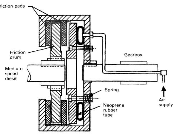
This type of clutch also uses a neoprene tube which is inflated by compressed air. Expansion of the tube produces a sandwich action between friction pads and disc.
The differences from the radial type:
- The friction disc or drum is spline mounted and therefore has axial float.
- The friction pads are also free to float axially, being mated with teeth machined peripherally inside the casing.
- Springs cause disengagement of the clutch when the tube is deflated.
Clutches produced by Wichita have a larger number of friction discs and pads than shown in the simplified drawing, which is intended to show the operating principle of axial air clutches. More discs and pads means more friction area in the same diameter, which is how an axial clutch carries a large torque in a short length.
10. Emergency operation
Failure of the air supply or other fault could render a clutch inoperative. To make provision for this eventuality, an emergency driving plate or set of temporary coupling bolts is provided. The emergency arrangement shown is for a combined clutch and coupling.
That is the arrangement to know before it is needed: the clutch can be made solid, and the engine and the shaft become permanently connected until the ship reaches port.
Prolonged use of the emergency solid coupling arrangement can result in serious damage to gear teeth. The evidence given is specific and worth repeating: the gearbox of at least one medium-speed engined ship had to be expensively replaced after six months' operation with the emergency coupling arrangement.
The reason is section 5. With the emergency coupling in, there is nothing between the engine's firing pulses and the gear teeth, and the teeth take the full torsional fluctuation for every hour the ship runs. The emergency coupling is a way of reaching port; it is not a repair.
11. What the engineer checks
| Item | What to look for |
|---|---|
| Gearbox oil pressure and temperature | Falling pressure or rising temperature at steady load — a pump, a cooler or a bearing |
| Gearbox oil condition | Water or metal in the oil; the magnetic filter tells you which gear or bearing is wearing |
| Clutch air pressure and the low pressure alarm | Proved at every manoeuvring station; the alarm never suppressed |
| Air system drains | Drained regularly — water in the air perishes the neoprene tubes and freezes in the lines |
| Clutch slip | A clutch that slips under load burns its linings; check for smell, heat and discolouration through the inspection openings |
| Flexible coupling | Oil seals leaking, spring packs for fretting, coupling stiffness if the torsional characteristics have changed |
| Reverse manoeuvre | The astern clutch engaging cleanly and the shaft coming up to speed; a slow or rough engagement is a valve or pressure problem |
| Emergency coupling | Its position known, its bolts and plate stored where they can be found, and the fact that it must come out at the first opportunity |