
Stern Tube Seals — Lip, Floating Ring and Radial Face
The seal is the part of a stern tube that fails, and the part that decides whether the ship can be worked afloat.
Key Principles at a Glance 5 points
- A stern tube seal has to hold against a pressure difference, follow the shaft as the hull deflects and the shaft droops, be replaceable, and not damage the shaft — and the inboard and outboard ends are not the same problem.
- A lip seal is a nitrile ring held against a renewable sleeve by its own elasticity and by a garter spring, and the rings face in different directions so that the assembly seals against pressure from either side.
- The Simplex tube has two rings forward and three aft, built up from the same flange, intermediate and cover rings — which is why the spares list for one is short.
- A radial face seal seals between two flat faces and is split throughout, and that split construction is what makes it the seal of the split stern bearings.
- A stern tube seal is not adjusted, it is renewed — and the rubbing surface is half the sealing joint, so a new seal fitted on a grooved liner will leak.
1. What the seal has to do
Each seal at each end must be capable of holding on its own. The inboard and outboard seals of an oil-lubricated tube are independently adequate, so the ship can be tipped or the shaft run with one of them out of service, but that is a planned condition with the other seal proved first — never an assumption. A seal that is passing is written up, not adjusted until it stops dripping.
A stern tube seal sits between two things that must not mix: the oil or the sea water inside the tube, and the sea outside it. It has to do that on a shaft that is turning, that is moving axially with the thrust, that is deflecting under the propeller's weight, and that is changing its position relative to the stern tube as the hull and the shaft expand by different amounts.
Four requirements follow, and they explain the whole design:
- It has to hold against a pressure difference. On an oil-lubricated tube the difference is deliberately small, because the header tank puts the oil pressure just above the sea pressure at the same depth (Chapter 8). On a water-lubricated tube the pressure difference is small for the same reason — the sea is on both sides.
- It has to follow the shaft. Hull deflection, vibration and differential expansion all move the shaft relative to the tube, and the seal has to accommodate that movement without losing face contact.
- It has to be replaceable. The stern bearing and the seals are the two things that fail, and the whole design of the after end is judged on whether they can be got at.
- It must not damage the shaft. A seal is a rubbing contact on a highly stressed, highly loaded shaft. Any seal that scores, grooves or frets the rubbing surface has traded a small problem for a large one.
The two ends are not the same problem. The outboard seal is in the sea and can lose its heat to the water; the inboard seal is in the tunnel, cannot, and has to be cooled by circulating oil (Chapter 8, section 4). And the outboard seal is the one that is only accessible from outside the ship.
2. The lip seal
A lip seal assembly consists of a number of nitrile rubber rings of special cross-section, sandwiched between bronze rings. Each individual rubber lip seal is held in contact with a renewable sleeve fitted to the shaft by its own elasticity and by a garter spring.
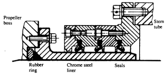
Three features of the design matter:
The garter spring does the loading. The lip is not held against the shaft by the fit of the rubber; it is held by a spring, and the spring is the part that has to survive the temperature. That is why the 110 °C limit in Chapter 8 is a limit on the spring's effectiveness as much as on the rubber.
The garter spring position is not the same on every ring. In the case of both forward sealing rings the spring is located aft of the ring's anchoring bulb. At the after end the two outboard sealing rings have their springs aft of the bulb as well, but the inboard ring of the after seal has its spring located inboard of the bulb. The rings therefore face in different directions, which is what lets the assembly seal against pressure from either side.
The rings are renewed by cutting and vulcanising the ends in position. A lip seal is a closed ring that has to be fitted over the end of a shaft that cannot be dismantled, so it is supplied as a strip, wrapped round the liner, and the joint vulcanised where it lies. The joint is a made joint and it is the first thing to suspect when a seal leaks after being changed.
3. How an assembly is built up
The Simplex stern tube is the standard example, and the ring count at each end is deliberate.
The Simplex tube has a forward seal with two rings and an after seal with three rings. The after seal carries the more because it is the one exposed to the sea, to the propeller wash and to the disturbance of the propeller itself; the forward seal has only the oil head to hold.
A larger view of the after seal shows that the seals are built up from three basic assemblies — the flange, intermediate and cover rings — and these parts can be used for either seal. That is the practical point for the engineer: the spares list for a Simplex tube is short, because the same three ring types make up both ends.
In some instances four or more sealing rings are installed, arranged so that one ring does not normally run on the shaft liner. In the event of leakage from the working seals, adjustment is made to bring the reserve ring into play. That is a spare seal carried in place — the liner under the reserve ring is unworn, so when the working rings have grooved their band of the liner the reserve ring can be brought on to fresh metal without the shaft being drawn.
Lip seals will accept misalignment, which is why they suit a shaft that droops under the propeller and moves with the hull.
4. The floating ring seal
A floating ring design was introduced by one manufacturer as a further answer to the same problem of misalignment.
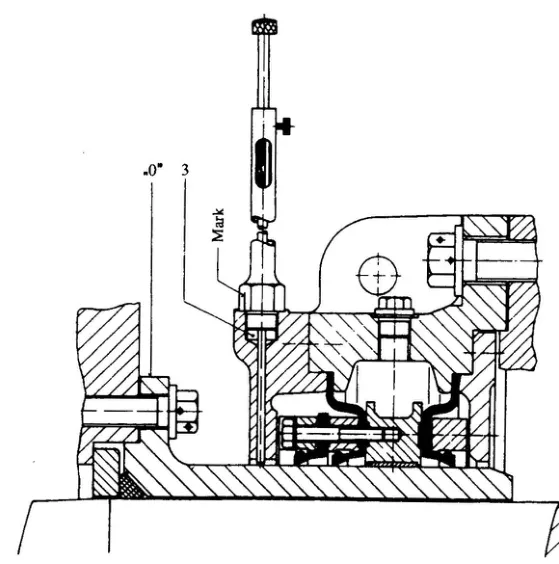
The advantage is that the seal is no longer required to accept misalignment by flexing its own lip. The lip stays square to the shaft, and the misalignment is taken up by the movement of the ring housing. That reduces the flexing duty on the rubber, which is the part that hardens.
5. The radial face seal
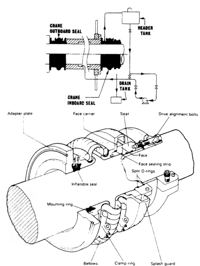
The second family of stern tube seal does not grip the shaft at all. It seals between two flat faces held together, one rotating with the shaft and one stationary.
The function of sealing against leakage around the shaft is effected by sustaining perfect mating contact between the opposing faces of the seal's seat, which rotates with the shaft, and of the main seal unit, which is stationary and clear of the shaft.
One of the principal features of the design and construction of this type of seal is the split construction of all component parts. That single feature is what makes the radial face seal the seal of the split stern bearings in Chapter 9: every part of it can be taken off and put back round a shaft that is still in place.
Three things hold the faces together:
- Spring pressure, which provides the closing force when the shaft is stopped;
- hydraulic balance, which uses the pressure of the oil or water being sealed to help close the faces rather than to open them; and
- a flexible mounting for the stationary face. The flexible member consists of a tough but supple reinforced bellows, and it is what allows the main seal unit to accommodate the effects of hull deflection and vibration.
The bellows member is clear of the shaft, and its flexibility therefore cannot be impaired by the things that ruin a flexible member mounted on a shaft — hardening, seizing, or a build-up of solids in the folds. The mechanical design principles also ensure continued sealing under fluctuating pressure conditions, that is, under changing draught.
6. The outboard seal in detail
The outboard seal is the one in the sea, and its materials are chosen for that. Taking the radial face type as the example:
The seat of the outboard seal is bolted to the forward face of the propeller flange or to the propeller boss. It is jointed with asbestos fibre material, and an O ring is fitted for a taper mounted propeller.
The rotating seat is a cast iron of high nickel content, about 14 per cent nickel, termed Ni-Resist, which is able to stand up to the corrosive effects of sea water.
The face seal is a synthetic termed ferrobestos, held in a carrier which, like the mounting ring, is of gunmetal. Clamp rings and the various nuts and bolts are of aluminium bronze.
The bellows assembly consists of monel metal springs in a cotton reinforced synthetic rubber.
The seal is protected by a rope guard. The rope guard is not a decoration: a length of rope or net wound round the shaft between the propeller and the seal will destroy the seal in a very short time, and the guard is what stops it reaching the seal face.
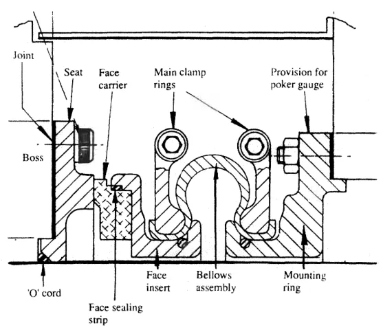
The drawing also shows the detail that makes the seal workable: provision for a poker gauge, so that weardown is measured through the seal rather than by taking it apart.
7. The inboard seal
The inboard seal does the same job in a much kinder place, and it is built to suit.
The materials of the inboard seal unit are not in contact with sea water, so cast iron is used for the seat, which is clamped to the shaft by a steel drive ring. The face carrier and mounting ring are of cast iron, with steel clamp rings for the bellows. The face seal and bellows are of the same materials as used outboard, but the springs in the bellows assembly may be of steel.
Two differences follow from the location, and both matter in service:
- The inboard seat is clamped to the shaft by a steel drive ring, so the rotating face is carried by the drive ring rather than bolted to a propeller boss. That is the joint that has to be broken when the seal is changed in the tunnel.
- The inboard seal has no sea to cool it. Its heat has to be carried away by oil circulation between the two inboard seals and the header tank, and a blocked circulation path is a hardened seal (Chapter 8, section 4).
Inboard and outboard seals are basically the same on oil-lubricated stern tubes, and each seal is adequate on its own while work is carried out on the other. That is the design intention, and it is what makes the next section possible.
8. Sealing the space to work afloat
There are three ways of holding the sea out of a stern bearing space while it is opened up, and all three are described in Chapter 9. The seal engineer needs to know which one is fitted, because it decides what can be done without docking.
The inflatable seal. An emergency sealing device can be incorporated into the design. The device, when inflated with air or liquid, forms a tight temporary seal around the shaft, enabling repairs to be made or a replacement seal fitted when the ship is afloat, without the shaft being drawn or drydocking being necessary. The Glacier-Herbert bearing carries two of them, each with its own air supply, in the periphery of a spigot, inflating against the inside of a carrier ring.
The bandage. Where inflatable seals are not fitted or have failed, an alternative to using the inflatable seals is to apply a bandage around the small gap between the carrier ring and the spherical seating ring. A bandage is a clamped rubber sleeve over the gap — simple, and dependent on the gap being small and clean.
The maintenance seal. The later split bearings carry a hydraulically engaged and mechanically locked maintenance seal between the forward end of the propeller boss and the stern frame, which closes the space inboard of the outboard working seal so that the bottom half bearing and the working seal can be drawn in together.
Whichever is fitted, the sequence is the same: prove the temporary seal, drain and check the space, and only then break the working seal.
9. What goes wrong, and what to look at
| Symptom | Most likely cause | First check |
|---|---|---|
| Header tank level falling | Outboard seal passing oil to sea | Rope guard intact; seal face for scoring or a trapped rope; oil temperature |
| Oil level rising, or water in the oil | Outboard seal passing sea water in | Sea water in the oil; white metal condition |
| Oil level rising, no water | Inboard seal passing, or circulation connections open to the tunnel | The top and bottom circulating connections between the two inboard seals and the tank |
| Inboard seal running hot | Blocked convection path | The circulating connections, and the tank level |
| Seal leaking after renewal | Vulcanised joint in the lip seal failed | The joint, and the liner band under the lip |
| Lip seal leaking, liner grooved | Seal has cut a groove in its own band of the liner | Ceramic filler in the groove, or a distance piece to move the seal on to fresh metal |
| Face seal leaking | Face not mating — spring, bellows or balance | Bellows folds for solids; face for scoring; clamp rings tight |
Two general rules sit behind the table.
A stern tube seal is not adjusted, it is renewed. A packed gland is adjusted; a lip seal and a radial face seal are units, and there is nothing on them to tighten. A seal that has started to pass will pass until it is changed.
The rubbing surface is part of the seal. The chrome steel liner, or the Ni-Resist seat, is half of the sealing joint. A new seal on a grooved liner will leak, and the two remedies — a ceramic filler, or a distance piece to displace the seal axially on to an unworn band — are remedies for the liner rather than for the seal (Chapter 8, section 5).