
Shafting Ancillaries — Friction Brake, Torsionmeter and Earthing Device
The shaft line carries three fittings that are not part of the drive and not part of the support, but that the engineer has to know about: the shaft friction brake and the trailing collar, which are there for when the engine has failed; the torsionmeter, which is how shaft power is measured and how the torsional characteristics of the line are checked; and the shaftline earthing device, which is a small electrical fitting that prevents a large and expensive mechanical failure.
Key Principles at a Glance 5 points
- Three items sit on or beside the shaft line and are not part of the drive: the shaft friction brake, the trailing collar, and the torsionmeter with the shaftline earthing device.
- The friction brake is fitted at the first coupling from the propeller shaft, so that the engine can be turned, opened and worked on with the propeller still and the shaft held.
- The trailing collar is set about 18 mm clear in normal service and only carries the weight of the trailing length of shaft once the shaft has been disconnected for towing.
- The torsionmeter constant belongs to the shaft and not to the meter: a 300 mm shaft 6.5 m long twisting 1 degree under 666 kN m gives a constant of 4.18, and a replacement shaft needs its own calibration.
- The shaftline earthing device holds the shaft-to-hull potential below 50 mV with a total resistance not exceeding 0.001 Ω, and it is mounted on the foremost intermediate shaft as close to the engine as possible so that the current is diverted before it reaches the main bearings.
1. What the ancillaries are
The earthing device is proved by its monitoring meter, not by its presence. A shaftline earthing device that has lost its brush contact reads as a floating potential on the meter, and a floating potential is a current path through the main bearings. The meter is read, the alarm is live, and the brushes and slip rings are checked on a schedule.
Three items sit on or beside the shaft line and are not part of the drive:
- the shaft friction brake, fitted so that the shaft can be held while the engine is examined;
- the trailing collar, fitted so that the shaft can be disconnected and allowed to idle when the ship is under tow; and
- the torsionmeter and the earthing device, which are instruments rather than machinery — one measures what the shaft is doing, and the other protects it from an electrical effect that would otherwise destroy its bearings.
None of them is essential to driving the ship. All of them are the difference between a manageable casualty and an expensive one.
2. The shaft friction brake
In case of engine breakdowns it is usually advisable to fit a shaft friction brake at the first coupling from the propeller shaft, so as to allow engine examination with safety.
The position is the point. The first coupling from the propeller shaft is the one place where a brake can hold the propeller shaft and everything forward of it independently of the engine, so that the engine can be turned, opened and worked on with the propeller still and the shaft held.
Two things follow from that:
- The brake has to hold against the propeller's own torque, which on a ship with a large propeller in a seaway is not a small load. A propeller in a following sea will drive the shaft whether anyone wants it to or not.
- It is a holding brake, not an operating brake. It is not used to stop the shaft in normal service; it is used to keep it stopped while work is done.
The brake is the shafting equivalent of the turning gear interlock on a main engine: a device that exists to make a maintenance operation safe, and that is worthless if it is not used.
3. The trailing collar
In case of towing after breakdown, a trailing collar working on a tunnel bearing face is often fitted to allow shaft disconnection and reduce propeller resistance by allowing idling.
The argument is straightforward. A ship under tow with the propeller still connected is dragging a propeller round against the resistance of the engine and the gearing, and the shaft is being turned by the water at a speed nobody controls. Disconnecting the shaft and letting the propeller freewheel removes that resistance and removes the uncontrolled turning.
Under normal conditions the collar is set about 18 mm clear.
That 18 mm is the whole of the design. The collar runs on the face of a tunnel bearing, but it does not touch it in normal service — the clearance is there so that the collar is only brought into contact when the shaft has been disconnected and is running free, at which point the collar carries the weight of the trailing length of shaft on the bearing face instead of letting it run on the journal. It is a steady bearing for a shaft that is no longer supported at its forward end.
A collar running on its face in normal service is a collar that has been set up wrongly, and it will run hot and wear the bearing face.
4. Why measure shaft power
There are two reasons for putting an instrument on a shaft, and they are different.
To know what the engine is delivering. The indicated power of a diesel engine is calculated from indicator diagrams, and the shaft power is what actually reaches the propeller. The difference between the two is the mechanical efficiency, and on a new ship or after a major overhaul the shaft power is the figure that tells you whether the engine is doing what the builder promised.
To know what the shaft is doing. A torsionmeter reads the twist in the shaft, and the twist is the torque. A continuous record of torque on a shaft line is how the torsional vibration characteristics of the installation are checked in service — which is what Chapter 13, section 5 and Chapter 11, section 9 are about. Very great care is advised in investigating the torsional vibration characteristics of a short, stiff aft-end installation, and the torsionmeter is the instrument that does it.
Strain gauges are the other instrument for the same purpose. Shaft stress is sometimes monitored in service by fitting strain gauges on the shaft. These register the alternating surface stretch and compression as the shaft rotates. Where a torsionmeter measures the twist over a length and gives a torque, a strain gauge measures the local surface stress at the point where it is fixed — which makes it the instrument for finding out what is happening at a particular place, such as a keyway or a liner end, rather than for measuring the power.
5. The torsionmeter and the shaft constant
The torsionmeter works from a single physical fact: a shaft under torque twists, and the angle of twist over a known length is proportional to the torque.
The first requirement is the determination of the shaft power constant from a shaft calibration. The calibration is done on the shaft itself, before it goes into the ship:
A shaft of 300 mm diameter and 6.5 m long is rigidly clamped at one end, and the free end has a clamp and lever, applied to which loads can be added at a radius of 3 m. A load force of 222 kN produces an angle of twist of 1 degree.
From that single measurement the constant follows:
torque applied = 222 kN × 3 m = 666 kN m for 1 degree of twist
and the power is the torque times the speed:
shaft power = 2π × N × T, with T in kN m
which for this shaft reduces to a meter or shaft constant of 4.18.
Thus, knowing the angle of twist in degrees for the given shaft length, the shaft power for the given revolutions per second can be determined. The requirement then for the torsionmeter is to measure the angle of twist in degrees between two points the correct datum length apart.
Two points are worth holding on to:
- The constant belongs to the shaft, not to the meter. A replacement shaft needs its own calibration, and a meter carried over from another shaft will read wrongly.
- The datum length is part of the calibration. The two measuring points have to be the distance apart that the constant was calculated for, which is why the measuring flanges are a fixed feature of the shaft.
6. The four types of torsionmeter
There are four types of torsionmeter, and the reasons for rejecting three of them are instructive.
| Type | How it works | Why it is or is not used |
|---|---|---|
| Mechanical | Gearing set from the shaft, with a differential screw reading device | Not popular, as wear immediately gives errors — a mechanical linkage on a rotating shaft wears, and the wear is indistinguishable from twist |
| Acoustical | The pitch of a note from a vibrating wire varies with the torque, that is, with the tension produced | Not popular at present, because of the difficulty of dealing with cyclic variations — it gives an average and hides the fluctuation |
| Optical | The lag of a light flash is indicative of the twist | Simple, but it tends to give an average value over a range of revolutions, and no indication of cyclic variations |
| Electrical | Variation of a transformer air gap due to the twist | Possibly the most accurate and the most popular |
The pattern is clear. The first three all fail on the same point: a torsionmeter that averages away the cyclic variation is useless for the job in section 4, because the cyclic variation is exactly what damages gear teeth and cracks shafts.
7. The electrical torsionmeter
Two sleeves are rigidly fixed to the shaft, having flanges at 180° to the shaft axis. Twist causes relative displacement between the flanges. Two cores are attached to one flange and the iron piece to the other, so that relative movement between the flange faces, due to shaft twist, alters the air gap of a differential transformer.
The primary circuit is wound to give the same polarity, and the secondary circuits are in opposition. The arrangement is a null-balance one, and the reading is taken by restoring the balance:
- With no torque the air gaps are equal, and the two secondary circuits are equal and opposite.
- When torque is applied, the air gaps become unequal, and a current flows in the secondary circuit, which can be read on the galvanometer.
- An identical unit is fitted in the indicator box. By rotation of the handle, the iron piece can be moved until the air gaps in the indicating unit are identical with those of the shaft unit. That restores the electrical equilibrium in the secondary circuit, the two currents are equal and opposite, and the galvanometer reads zero.
- The amount of movement at the indicating box dial is indicative of the angle of twist restoration required, and hence gives the angle of twist for the length of shaft between the two flange faces in the shaft unit.
By application of the meter constant and the revolutions per second, the shaft power is thus determined. A motor-driven interrupter to give an a.c. supply is required if the mains are d.c.
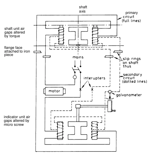
The null-balance method is why the electrical type is accurate: the reading does not depend on the magnitude of a current, which drifts, but on the position of a dial that restores a balance, which does not.
8. The dynamometer, for comparison
The dynamometer is the other way of measuring shaft power, and it is worth knowing because it appears in the same discussions.
Consider the hydraulic type. The engine under test drives the shaft to which the rotor is directly coupled. The shaft bearings are inside the casing containing the stator, which is free to swivel on trunnion supports. Each face of the rotor has pockets or cells of semi-elliptical or oval cross-section, divided from one another by oblique 45° vanes, and the stator is similar. Water enters at the stator inlet channel, passing between the 45° vanes into the rotating rotor, and is constantly circulated around the cells in a vortex action, so that the torque is transmitted from rotor to stator through the water. This torque tends to turn the stator, and this action is resisted by a load measuring device, so that the resisting torque equals the applied torque and is thus measured.
For testing in both directions of rotation, two rotors are provided — one used astern, the other ahead.
The difference from the torsionmeter is the whole point: a dynamometer is a load, and a torsionmeter is an instrument. A dynamometer is used on a test bed, where the power has to be absorbed as well as measured. A torsionmeter is used in the ship, where the propeller is the load and only the measurement is wanted.
9. The shaftline earthing device — why it is needed
This is the ancillary that most directly prevents an expensive failure.
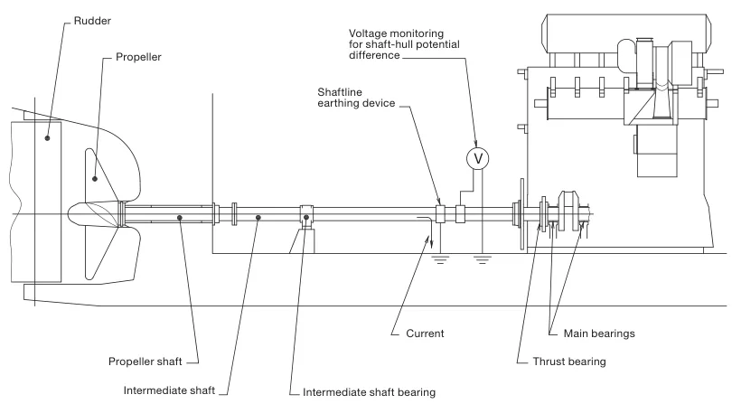
A difference in the electrical potential between the hull and the propeller shaft will be generated, due to the difference in materials and to the propeller being immersed in sea water. The propeller is bronze or stainless steel, the shaft is steel, the hull is steel, and the sea is an electrolyte between them. The result is a galvanic cell with the shaft as one of its electrodes.
In some cases the difference in the electrical potential has caused spark erosion on the thrust bearing, the main bearings and the journals of the crankshaft of the engine.
That is the failure mode, and it is worth stating plainly: the current path is hull — bearings — crankshaft — shafting — propeller — sea — hull, and where the current crosses a bearing oil film it sparks and erodes the metal. The bearings that fail are the main engine bearings and the thrust bearing, which are the most expensive bearings in the ship and the ones whose failure stops the ship.
In order to reduce the electrical potential between the crankshaft and the hull, and thus prevent spark erosion, a highly efficient shaftline earthing device must be installed.
10. The earthing device and its construction
The shaftline earthing device should be able to keep the electrical potential difference below 50 mV d.c.
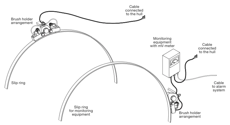
The device consists of two silver slip rings, two arrangements for holding brushes including connecting cables, and monitoring equipment with a mV-meter and an output signal for alarm.
The specification matters, because this is a device that has to pass a large current through a very small resistance:
| Item | Requirement |
|---|---|
| Slip rings | Solid silver, or backing rings of copper with a silver layer all over |
| Life of the silver layer | Minimum 5 years |
| Brushes | Minimum 80 per cent silver and 20 per cent graphite, to ensure sufficient electrical conducting capability |
| Resistivity of the silver | Less than 0.1 μΩ m |
| Total resistance, shaft to hull | Must not exceed 0.001 Ω |
| Cable to the hull | Cross-section not less than 45 mm², and the length of the cable to the hull should be as short as possible |
The 0.001 Ω total resistance is the figure that decides everything. The whole purpose of the device is to give the current a path of negligible resistance, so that the potential difference — and therefore the current through the bearings — is reduced to nothing. A dirty slip ring or a worn brush adds resistance at exactly the wrong place.
11. Where it is fitted
The shaftline earthing device slip rings must be mounted on the foremost intermediate shaft, as close to the engine as possible.
The reason follows from section 9. The current path is from the propeller forward through the shaft line to the engine. The earthing device is a short circuit to the hull, and putting it as far forward as possible — right at the engine — means that the current is diverted to the hull before it reaches the main bearings and the thrust bearing. Put it at the after end and the current still passes through everything.
When a generator is fitted in the propeller shaft system, where the rotor of the generator is part of the intermediate shaft, the shaftline earthing device must be mounted between the generator and the engine.
Note that only one shaftline earthing device is needed in the propeller shaft system.
12. Monitoring and alarms
A shaft-to-hull monitoring equipment with a mV-meter and with an output signal to the alarm system must be installed, so that the potential and thus the correct function of the shaftline earthing device can be monitored.
The instrument ranges and settings:
| Item | Setting |
|---|---|
| Signal to the alarm system | 4 – 20 mA |
| mV-meter | With a switch for changing range |
| Primary range | 0 to 50 mV d.c. |
| Secondary range | 0 to 300 mV d.c. |
| Normal reading, device working correctly | 10 to 50 mV d.c., depending on propeller size and revolutions |
| Alarm set-point, high alarm | 80 mV |
| Alarm delay | 30 seconds |
| Alarm cut-off | When the engine is stopped |
Two things in that table are worth the engineer's attention.
The normal reading is not zero. A device working correctly reads somewhere between 10 and 50 mV, and it varies with propeller size and revolutions. A watchkeeper who expects a zero reading will report a good device as faulty, and one who expects any reading to be normal will miss a device that has failed.
The 30-second delay and the engine-stopped cut-off are both deliberate. The delay stops a momentary reading from raising an alarm; the cut-off stops an alarm when the engine is stopped, because with the shaft still the potential behaves differently and an alarm then would be meaningless.
The device is checked by reading the meter, and the meter is the only proof that the device is working. A slip ring with a worn silver layer, or a brush that has lost contact, is a shaftline earthing device that exists but does not earth — and the reading on the meter will tell you before the main bearings do.