
Shaft Couplings and Coupling Bolts — Flange, Hydraulic and Muff
The shaft line is built in lengths, and every joint between them is a place where the drive has to pass from one shaft to the next and where the line has to be got true.
Key Principles at a Glance 5 points
- A flange coupling transmits torque partly by friction between the faces and partly through the shanks of the bolts, holds the two shafts concentric, and gives a joint that can be broken for survey.
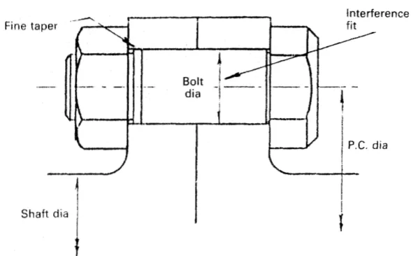
- A clearance bolt provides the friction but not the shank load; a fitted bolt provides both — until it is tightened, when the elongation thins the shank and the interference fit is lost.
- The Pilgrim hydraulic bolt makes the stretch part of the design: it is stretched hydraulically to enter the hole, the nut is nipped up, and releasing the pressure gives both the predetermined bolt load and the diametrical re-expansion of the fit.
- The muff coupling at the inboard end of the tailshaft is what lets the shaft be drawn out astern through the stern tube instead of being lifted out over the top.
- The muff coupling is fitted with oil injected between the sleeves to overcome their friction, and the grip is proved by measuring the increase in outer sleeve diameter against the figure stamped on it.
1. What a flange coupling has to do
A coupling bolt is tightened to a calculated load, and it is the load that makes the joint. A bolt driven in with a hammer, or tightened until it feels right, has either not got the interference the design needs or has destroyed it. Coupling bolts are fitted and removed with the maker's pressure and the maker's lubricant, and the push-up or the pressure is recorded.
A flanged coupling between two lengths of shaft does three things at once:
- it transmits the torque — partly by friction between the flange faces, and partly through the shanks of the bolts;
- it holds the two shafts concentric; and
- it gives a joint that can be broken for survey, for realignment, or for withdrawing the tailshaft.
The faces of the flanges are smooth turned — except where undercut in the centre area — with the bolt holes carefully bored and reamed to give an accurate finish. The accuracy of the faces and the holes is what makes the joint work; a flange face that has been bruised, or a hole that has been reamed oval, cannot be made good by tightening the bolts harder.
Torque is transmitted by the friction between the flanges and also through the shanks of the bolts. Each tightened bolt holds the flanges hard together in the area local to it, so a circle of bolts is needed for a good all-round grip — the friction is not distributed evenly across the face but is concentrated round each bolt.
The design of flange couplings can be checked by formulae given in the classification society rules.
2. The three kinds of coupling bolt
| Type | Shank | Takes load through | Problem |
|---|---|---|---|
| Clearance bolt | Parallel, clearance in the hole | Friction between the flanges only | Provides the friction but not the shank load |
| Fitted bolt | Parallel, interference fit in the reamed hole | Friction and the shank | Loses its fit when tightened (section 3) |
| Tapered bolt | Tapered, driven into a matching taper | Friction and the shank | Needs a matching taper; driving in is a risk |
Shaft coupling bolts are tightened to force the faces of the flanges together, so that friction between the faces will provide some proportion of the drive. However, fitted bolt shanks are also designed to take some load. That is the requirement the clearance bolt cannot meet: a clearance bolt could provide the first requirement but not the second.
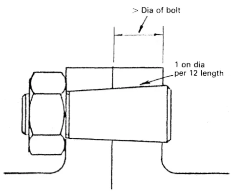
A tapered bolt can be used instead of a conventional coupling bolt to obtain a good fit and the required tightening — the taper gives an interference fit along the whole shank rather than only where the reamer happened to cut.
3. Why tightening a fitted bolt loses the fit
This is the point that explains the existence of the hydraulic bolt, and it is worth following through.
The elongation of a bolt when tightened causes a reduction in cross-sectional area. The relationship between the change in length and the change in cross-sectional area is summarised by Poisson's ratio.
In a clearance bolt this is not a problem — the shank is not touching the hole anyway.
But with a normal fitted bolt, positive contact between the accurately machined bolt and the reamed hole is lost when the bolt is tightened. The bolt is stretched, so it is thinner, so the interference fit that was there before tightening is gone. A normal fitted bolt, when tightened and subjected to a reduction in cross section, fails on the second count — carrying load through the shank — and is probably damaged by fretting as well.
One answer is to use an oversize bolt and cool the shank — probably with liquid nitrogen — to contract it before insertion. The effect of the low temperature, and the possibility of the steel becoming brittle as a result of the cooling, both have to be considered.
The better answer is to make the stretch part of the design.
4. The Pilgrim hydraulic bolt
The Pilgrim hydraulic bolt uses the principle embodied in Poisson's ratio to provide a calculated and definite fitting force between bolt and hole.
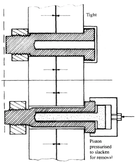
The bolt is hollow. Before being fitted it is stretched with hydraulic pressure applied to an inserted rod from a pressure cylinder screwed to the head of the bolt. The stretching makes the bolt diameter small enough for insertion into the hole, after which the nut is nipped up. Release of the hydraulic pressure allows the bolt to shorten, so that:
- a predetermined bolt load is produced, and
- diametrical re-expansion gives a good fit of the shank in the hole.
To remove it, the piston is pressurised again to slacken the bolt so that it can be withdrawn.
These bolts, used in flange couplings and in flange-mounted propellers, have the advantage that they are easily removed for inspection and maintenance, and the problem of driving in is avoided. On a shaft line that has to be broken for survey, that is not a convenience — it is the difference between a job that can be done properly and one that cannot.
5. The muff coupling
An alternative to the conventional flange couplings for the tailshaft, the muff coupling allows the shaft to be withdrawn outboard.
That is its whole purpose. With flange couplings throughout, the tailshaft can only be removed by taking the propeller off and drawing the shaft inboard — or by lifting it out. With a muff coupling at the forward end of the tailshaft, the flange at the after end can pass through the stern tube and the shaft can be drawn out astern.
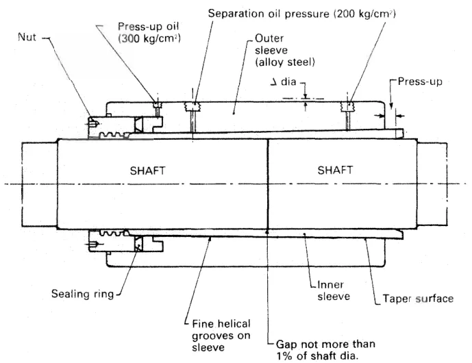
The SKF coupling consists basically of two steel sleeves. The thin inner sleeve has a bore slightly larger than the shaft diameter, and its outer surface is tapered to match the taper on the bore of the outer sleeve. The nut and sealing ring close the annular space at the end of the sleeves.
6. Fitting the muff coupling
The sequence is hydraulic throughout, and it is worth setting out because every step has a purpose:
- With the coupling in position, the outer sleeve is hydraulically driven on to the tapered inner sleeve.
- At the same time, oil is injected between the contact surfaces to separate them and so overcome the friction between them. Without the injected oil the sleeves could not be driven together at the pressures available.
- Oil for the operation is supplied by hand pumps: two for the forced lubrication, and another hand or power pump for the driving oil pressure.
- When the outer sleeve has been driven on to a predetermined position, the forced lubrication pressure is released and drained.
- Oil pressure is maintained in the hydraulic space until the oil between the sleeves drains and normal friction is restored. This is the step that makes the joint: while the oil is still between the surfaces there is no grip.
- After disconnecting the hoses, plugs are fitted and rust preventive applied to protect the exposed seatings. A sealing strip is pressed into the groove between the end of the sleeve and the nut.
The grip of the coupling is checked by measuring the diameter of the outer sleeve before and after tightening. The diameter increase should agree with the figure stamped on the sleeve. That figure is the proof that the interference is what the designer intended, and it is the only proof there is.
To disconnect the coupling, oil pressure is brought to a set pressure in the hydraulic space. Then, with the shafts supported, oil is forced between the sleeves. The outer sleeve slides off the inner at a rate controlled by the release of the hydraulic oil pressure. The shafts must be supported before the grip is released, because the coupling is what is holding them in line.
7. The muff coupling in the shaft line
The muff coupling is the joint that makes the rest of the after-end design possible:
- It is used at the inboard end of the tailshaft where the after end is flange mounted, so that the tailshaft can be entered or withdrawn from aft.
- It is the coupling fitted to the Glacier-Herbert stern bearing installation, where the shaft is installed from the outboard end with its rotating liner and carrier ring already assembled (Chapter 9).
- It is used with the withdrawable stern gear systems, where the bearing and seal assembly is drawn inboard along the shaft (Chapter 9).
- The same oil injection principle is used for mounting the propeller itself (Chapter 5), with the same check — the push-up is measured and recorded.
8. What to look at on a coupling
On the flange coupling:
- The flange faces, for bruising, fretting marks and rust staining. Fretting between the faces means the friction drive is not working and the bolts are carrying more than their share.
- The bolt holes, for ovality and for fretting. A reamed hole that has been fretted is no longer a fit, and the coupling will not hold its alignment.
- The bolt shanks, at every survey, for fretting damage and cracking. This is the reason the Pilgrim bolt is valued: it comes out without being driven.
- The register or spigot between the flanges, if one is fitted. It is what holds the two shafts concentric, and it is easily damaged by careless separation.
On the muff coupling:
- The stamped figure on the outer sleeve, and the diameter increase actually achieved at the last fitting.
- The sealing strip in the groove between the sleeve end and the nut, and the rust preventive on the exposed seatings. A muff coupling that has been left with its seatings bare will be a muff coupling that will not come apart when it has to.
- The oil injection grooves and ports, for blockage. If the oil cannot be got between the surfaces, the coupling cannot be released without damage.
- Any sign of the coupling having crept — a change in the position of the outer sleeve relative to its recorded position is the beginning of a lost grip.
A coupling that has been found loose is not retightened in place. The joint is broken, the surfaces inspected and measured against the maker's figures, and the coupling refitted with the push-up or the diameter increase recorded.