
Engine Bearings — Renewal, Crosshead to Thrust Block
How oscillating bearings keep an oil film, how a main bearing is renewed in 22 steps, and how tilting pads carry the propeller.
Key Principles at a Glance 6 points
- Rotation builds its own oil wedge (hydrodynamic); oscillation and slow rubbing start metal-to-metal (boundary) until speed lifts the film.
- The crosshead bearing only loads its lower half and only films at speed — so oil is injected on schedule, ~20° before top dead centre.
- Thin shells seal by crush: circumferential overlength wedges them against the housing with radial grip — no crush, no heat path, no bearing.
- Run-outs stop edge-scraping and bore reliefs forgive misalignment; both exist because a protruding shell edge starves the film.
- The thrust block turns propeller push into hull push through 7–8 self-tilting white-metal pads per side, each building its own wedge.
- Renewal runs permits → safe → measure → lift → mark and land: depth gauge zeroed before the LO line comes off, keep marking noted before it leaves the saddle, wood base never steel.
1. Two Lubrication Regimes
Fast steady rotation drags oil into a converging wedge that lifts metal off metal — hydrodynamic film, the design condition. Slow, reversing or oscillating motion never builds the wedge, so surfaces rub through a boundary film instead. Every bearing below is a strategy for living in one regime or surviving the other: crossheads oscillate (boundary at dead centres), mains rotate (hydrodynamic throughout), thrust pads tilt to manufacture their own wedge angle.
2. Top End — Guides and Crosshead
Guide shoes on the crosshead ends dump rod side-thrust into the frame on white-metal strips, shim-aligned fore-and-aft with a locating pin stopping crosshead-pin rotation. The crosshead (top-end) bearing is the hard one: oscillation means boundary film at each swing end, hydrodynamic only mid-swing — so cooling oil is injected between pin and lower shell exactly when load is lowest, ~20° before top centre, through shell grooves (sometimes edge-throttled to hold pressure). Big polished pins, continuous lower shells for area, tin-aluminium on steel with white-metal overlay, clearances non-adjustable: at maximum, renew.
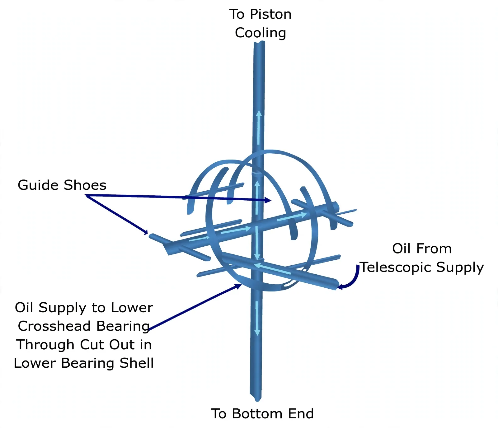
Sulzer's RTA variant runs a continuous lower shell in the rod top fed by 10–16 bar booster oil through a swinging arm that also carries 4 bar piston-cooling oil — same problem, higher-pressure answer.
3. Bottom End and Mains — Crush Is the Design
MAN bottom ends feed down rod drillings into white-metal or tin-aluminium thin shells (tin-flashed halves), screwed against rotation, torqued exactly to the book so caps never twist on the rod. On trunk engines the top half carries most of the cycle with a brief mid-cycle transfer below; crankshaft drillings deliver the oil, shell holes and housing grooves distribute it.
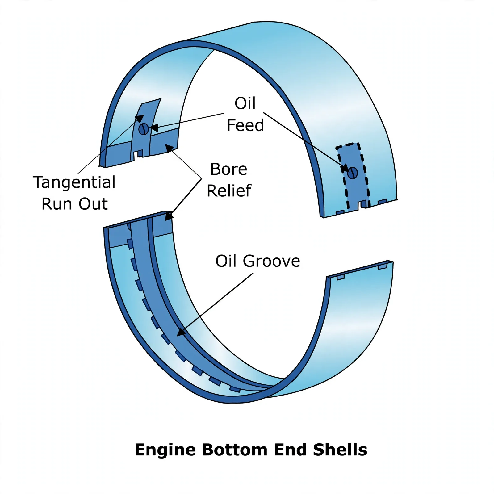
Main bearings (2–2.5% wall thickness, steel-backed, full-length rigid support against fretting) add two anti-starvation details: tangential run-outs ease oil into the loaded zone instead of scraping it away, and bore reliefs absorb minor misalignment so no shell edge stands proud as a scraper. Shoulders and screws or pins stop axial walk and rotation; cover-fed oil spreads through a radial groove and shell bores. Trunk-engine mains mirror this with grooved top halves, lugged lower halves, and block-drilled supply.
4. Gudgeon Pin — Frozen Bush, Floating Pin
Trunk small-ends repeat the crosshead problem: bottom-loaded, film-fragile. The answer is area (generous lower bush with spreader grooves) plus fit discipline — bush frozen into the rod, pin floating clearance-fit in the skirt on circlips for self-alignment, fed from the bottom end up the rod (or from piston-cooling oil), with a top-skirt scraper ring stripping carry-over before it reaches combustion.
5. Thrust Block — Propeller Push Becomes Hull Push
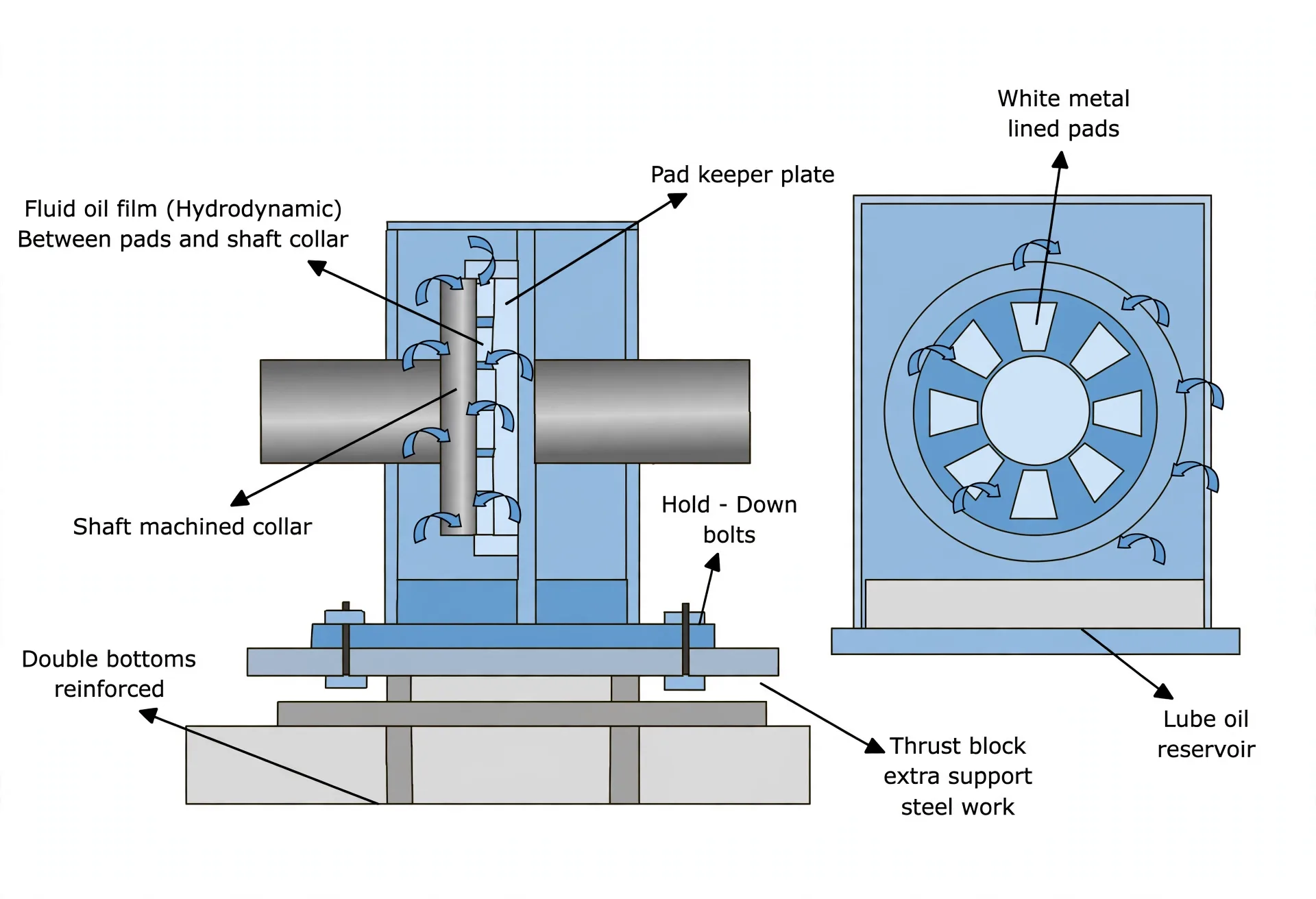
Sited aft of the engine (driving end on direct-reversibles), the Michell block anchors propeller thrust into strengthened structure through holding-down bolts. Seven or eight white-metal pads per side of the integral collar each pivot like a sliding block, tilting into the exact wedge angle the film needs; spray nozzles between pads feed both faces from the LO pumps, and a dedicated sump with cooling coils holds temperature.
6. Main-Bearing Renewal — the 22-Step Discipline
Idea in one line: the shaft never leaves its bed — the keep drops, the shell rolls out around the journal, and every step before the first bolt proves nobody can start the engine mid-job (Bearing.pdf p18).
Renewal is a permits-first ritual: company permission and immobilisation certificate (main engine unavailable for the stated period), manual studied in a toolbox meeting, tools and spares staged, risk assessment with everyone involved. Only then does steel move:
Paper before steel. Company permission; immobilisation certificate from the port; manual read plus toolbox meeting on the procedure; tools and spares staged; risk assessment signed by everyone on the job.
Make the engine unstartable and breathable. Starting-air valve shut; indicator cocks open on all units; turning gear engaged in remote under the in-charge's hand; main LO pump stopped; crankcase doors open, blowers on, space ventilated; enclosed-space checklist prepared; entry only after ventilation, in full PPE.
Measure first. Depth-gauge tool calibrated and zeroed; LO-pipe screws opened and the gauge inserted to read keep-to-journal clearance; reading compared against history and the new shell's figure — the number decides the renewal, not the eye.
Lift and land. LO line disconnected; crank throw barred toward the exhaust side for access; hydraulic jacks mounted and stud nuts eased; lifting tool on the keep, hoisted by pulley and wire; keep marking noted for correct refit direction; keep guided out with a second chain block and landed on a wooden base — never on steel.
Keep lifting and marking: lift with control, mark before the keep leaves its saddle — a reversed keep wipes on first firing. And measure before disconnecting anything: once the LO line is off and the jacks are on, the as-found clearance is gone forever.