
The Shafting System — What It Carries and How It Is Sized
The shafting system carries the engine's torque out through the hull to the propeller, takes the propeller's thrust back into the ship, and holds the weight of the propeller while the hull bends underneath it.
Key Principles at a Glance 5 points
- The system is the thrust shaft, the main thrust block, the intermediate shafting in its bearings, the stern tube, the propeller shaft and the propeller — and it does three jobs: carries the torque, takes the thrust into the hull, and holds the weight of the propeller.
- The propeller mass pulls the after end of the shaft down and tilts the forward part up, so the stern tube bearing is slope bored or given a downward lie and the next bearing forward is negatively loaded — which is why the aftermost tunnel bearing is a full bearing.
- The bending moment from the propeller is of the order of 33 kN m in still water, being 45 kN of weight over 0.75 m, and it rises considerably when the propeller races out of the water; the factor of safety on a tailshaft is therefore usually over 12.
- The proportions run from 1.15 × the intermediate shaft diameter at the thrust collar root to (d × 1.14) + P/K for the propeller shaft, where K is 144 for a protected shaft and 100 for all others.
- Stiffening the tank tops and engine seating holds the central deflection to about 13 mm over the engine room length, and the engine main bearings are lined down in a deflection curve of about 1 mm so that the shafting is true at half load.
1. What the system consists of
The shafting is a designed system, not a set of separate parts. Every alignment figure, every bearing clearance and every seal in it is set against the others, so nothing on the shaft line is altered — no chock packed, no bearing lifted, no coupling broken — without recording the change and checking what it has done to the rest.
Working from the engine aft, the system is:
- the thrust shaft, coupled to the engine or gearbox, carrying the thrust collar;
- the main thrust block, which transfers the thrust to the hull and limits axial movement;
- one or more lengths of intermediate shaft, supported in tunnel bearings or plummer blocks;
- the stern tube, through which the last shaft passes out of the hull;
- the propeller shaft, also called the tailshaft, which is the one that carries the propeller; and
- the propeller itself, mounted on a taper, a flange or a keyless fit.
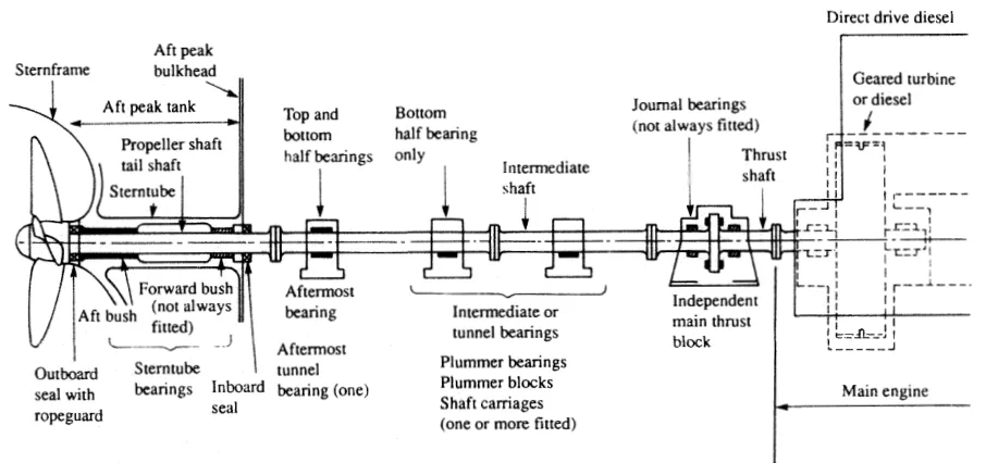
The same arrangement is drawn below in the simpler form used for a direct-drive diesel. Note that the aftermost tunnel bearing is a full bearing top and bottom, while the intermediate bearings are bottom half only with the top acting as a cover.
2. The three jobs, and where each one is done
Torque. The engine's turning moment is carried by the whole line of shafting, and the shaft is sized for the maximum torque rather than the mean, because the turning moment of a reciprocating engine is not steady.
Thrust. The propeller pushes the ship through the water, and the reaction — forward thrust when running ahead, astern thrust when manoeuvring — arrives at the thrust collar and is taken out by the thrust block into the hull structure. The thrust shaft is the only part of the line that sees this load at full magnitude, which is why the diameter at the collar root is larger than the rest.
Weight. The propeller is a heavy mass hanging on the end of the shaft, and the shaft has to hold it. This is the load that shapes the whole design of the after end, and it is dealt with in section 5.
End thrust on the shafting itself is small compared with the other stresses. A thrust ahead of about 500 kN would induce a compressive stress of only about 1.73 kN/m² in the shaft, which can normally be ignored — except where the thrust is transmitted to the hull, that is, at the base of the thrust collar, where the structure has to be able to take it.
3. Shaft material and manufacture
The intermediate shafting and the propeller shaft for a fixed propeller are of solid forged ingot steel, and usually with solid forged couplings.
Shafts are machined all over, but they are of larger diameter and smooth turned in way of the bearings — the bearing journals are the surfaces that have to run in a film of oil, and the finish matters there.
Everything to do with the couplings — the turned faces, the bored and reamed bolt holes, the friction between the flange faces and the load taken through the bolt shanks, the hydraulic bolt and the muff coupling — is in Chapter 4. The proportions of the flanges and bolts, and the rule figures they are checked against, are in section 7 of this chapter.
4. Why the engine's position changed, and changed back
The conventional midships position for the engines of older vessels, with the exception of tankers, was based on low engine power and strong hull construction. The shafts were long, but being of moderate diameter they were able to flex with the hull as loading or other conditions changed, and in heavy weather. A loading or ballast condition which changed hull shape and shaft alignment to an unusual degree sometimes caused higher temperature in some bearings due to uneven load distribution. Shaft stress was the hidden factor.
The trend towards higher engine powers and the positioning of engines aft gave rise to large diameter, short length shafts of increased stiffness. The consequence was excessive vibration and resulting damage in many dry cargo and container vessels, and this caused engines to be moved back towards midships — leaving one cargo compartment aft of the machinery space. Hull vibration seems to be less of a problem in ships with that one compartment aft of the machinery space.
Hull detuners intended to reduce vibration have been fitted in steering gear compartments, but the improvement to many ships seems to be marginal.
The practical lesson for the engineer is that the position of the engine in the ship is a shafting decision as much as a cargo decision, and that a short stiff shaft line is not automatically an easier one to keep aligned.
5. The weight of the propeller is the real problem
The propeller shaft is fixed at the forward end and free at the after end, and the free end carries the propeller. The propeller mass pulls the outer end of the shaft down, so that there is a tendency for edge loading of the stern tube bearing to occur. The forward part of the propeller shaft is tilted upwards.
Two things follow from that.
First, the stern tube bearing is deliberately bored to suit it. The remedy for edge loading due to propeller shaft droop is to arrange for the stern tube bearing to be slope bored, or installed with a downward lie, so that the shaft weight is fully supported along the bearing surface rather than carried on its after edge.
Second, the arching lifts the inboard end. Because the propeller end droops, the inboard end of the tailshaft is tilted up, so that the next bearing forward — whether in the stern tube or beyond — tends to be negatively loaded. That negative load is why the aftermost tunnel bearing is a full bearing and why the forward end of the stern tube bearing is treated as a bearing that may be carrying the shaft up rather than down.
Weardown makes it worse. As the stern tube bearing wears, the alignment gets worse, and whirl may give an additional problem on top of it. This is the reason the weardown figures in Chapter 6 matter as much as they do: the shaft does not merely settle, it starts to whip.
The deformation imposed by the propeller mass remains after the rest of the shaft system is installed. It is not a temporary condition of the fitting-out stage.
6. Bending from the propeller, worked through
It is worth putting a number on the bending the propeller puts into the shaft, because it is the reason the factor of safety on a tailshaft is so high.
Take the propeller immersed in still water and treat the shaft as a simply supported cantilever at the point where it enters the hull. The weight of the propeller, after allowing for the upthrust of the water, is of the order of 45 kN. The bending moment at the hull is then the weight times the distance out:
45 kN × 0.75 m ≈ 33 kN m
That is fairly appreciable in itself, but when the propeller rises out of the water due to racing in heavy seas the value is increased considerably. The bending moment must therefore be assessed as a heavy, fluctuating and largely indeterminate one.
Set against that:
- the shaft is worked in a corrosive medium, and there is a possibility of direct contact between shaft and sea water in spite of the precautions taken to exclude it. Some authorities consider that the fatigue strength of a part in sea water is only about 25 per cent of that of the same part in air;
- the shaft is simultaneously in fluctuating combined bending and twisting, with end thrust added; and
- the magnitude of the fluctuation is not known accurately.
The factor of safety employed is therefore high, usually over 12. A tailshaft is not a shaft that is sized to the load; it is a shaft that is sized to the uncertainty.
7. How the shaft diameters are arrived at
The rules are empirical formulae based on theory and on long experience, and there is a separate formula for each type of machinery — steam turbine, turbine-electric, and motor machinery in all its variations of number of cylinders, firing intervals and cycle.
The intermediate shaft is calculated first and is treated as a shaft in torsion. From the required power and a safe stress the diameter is arrived at, and the couplings and coupling bolt dimensions follow. The fundamental torsion equation T/J = q/r = Gθ/l is the basis of most of the calculation. A slight compensation is allowed for end thrust, bending, and the variation of torque caused by propeller racing.
The thrust shaft is calculated almost the same way, but virtually no misalignment bending occurs in such a short shaft over a stiffened tank top. The thrust action on the collar requires a thicker diameter at the collar root, and once clear of the thrust pads the shaft can be tapered down to the intermediate shaft diameter.
The propeller shaft is subject to torque and end thrust like the intermediate shaft, but its torque variation due to propeller racing is more fluctuating, and it carries the bending from the propeller weight described in section 6.
A few of the proportions worth knowing, from the classification rules for a Class I passenger vessel:
| Item | Proportion |
|---|---|
| Thrust shaft at collar root | 1.15 × intermediate shaft diameter d |
| Sterntube shaft (a shaft passing through a stern tube that does not carry the propeller, as in a twin-screw bracket arrangement) | 1.14 d |
| Propeller shaft (carrying the propeller) | (d × 1.14) + P/K |
| Any part of a shaft in contact with sea water | increase the calculated size by 2½ per cent |
| Stern bush length, traditional types | 4 × shaft diameter inside the bush |
| Coupling flange thickness | at least the bolt diameter; the propeller shaft coupling at least 0.11 d |
| Fillet radii on shafts | 0.08 × diameter |
| Crankweb thickness parallel to the shaft | 0.625 × crankshaft diameter |
| Crankweb thickness radially around the crankpin | 0.438 × crankshaft diameter |
In the propeller shaft formula, P is the propeller diameter in mm and K is 144 where a continuous liner is fitted, where the shaft is oil lubricated and sea water is excluded, and where the shaft material is resistant to corrosion by the water in which it will operate. K is 100 for all other shafts. The difference between the two figures is the measure of how much easier it is to keep a protected shaft alive.
In all cases the shafting, couplings and bolts must provide resistance to astern pull as well as to the ahead torque.
8. Shafting stresses in service
Three features of the loading are worth holding on to, because they explain most of the inspection and survey requirements in the later chapters.
The torsional stress is fluctuating, and the ratio of maximum to mean torque is high for internal combustion engines. For a single-cylinder engine the maximum to mean torque ratio is about 6:1. Adding cylinders smooths the turning moment and reduces the ratio — a four-cylinder arrangement can bring it down to about 2.5:1 — but it does not remove the fluctuation. The shafting sizes must be based on the maximum torque, not the mean.
The bending on a crankshaft is heavy and is applied rapidly, effectively as a form of impact, which is another reason the margins are generous.
The propeller shaft carries the most uncertain combination of all — fluctuating combined bending and twisting of uncertain magnitude, end thrust, and the possibility of corrosive attack — and it is sized accordingly.
9. The bedplate and tank top are part of the system
The alignment of the shafting is only as good as the structure that holds it, and two structural figures are worth remembering.
Stiffening of tank tops and engine seating supports, together with the use of rigid bedplates, can reduce central deflection to a maximum of about 13 mm over the engine room length, and to about 2 mm maximum over the bedplate from the no-load to the full-load condition.
Invariably the bedplate has a sag form when light ship of about 1 mm, and a hog form when fully loaded of about 1 mm. An engine crankshaft set true at light ship could, when hogged 2 mm, introduce static bending stresses of about 90 MN/m². Most engine builders have their own records and experience for dealing with this.
The usual answer is to line the engine main bearings down in a deflection curve, of 1 mm maximum at the centre of the length, for a new engine. The shafting is then true at half load, and the maximum static bending stresses are 45 MN/m² on each side of that, instead of 90 MN/m² all on one side. In many cases the deliberate offset needed is only about one tenth of those figures. The degree of offset depends on the type of ship and engine, the stiffness, and the variation with loading, and can only be settled by experience.