
Cooling, Lubrication and Fuel — Systems and the Tanks Checked Before Starting
The three fluid systems that keep the auxiliary engine alive — the cooling water, the lubricating oil and the fuel.
Key Principles at a Glance 5 points
- The pre-operation check list names nine tanks and levels that must be confirmed before an auxiliary engine is started, and each one corresponds to a system.
- Two of them are easy to overlook and both matter: the governor oil level, because a hydraulic governor with low oil will not control the engine, and the outboard bearing oil level, because the bearing carrying the alternator end of the shaft is lubricated separately on many sets and is not visible from the engine.
- The jacket water and injector cooling water expansion tanks must be checked for proper level and that the pumps are in operation.
- The inlet and outlet valves of the nozzle and jacket water systems must be checked for correct open or closed position before the heaters are energised.
- The list runs: cooling water header tank, oil sump tank, cylinder lubricating oil tank if provided, fuel service and settling tank, diesel storage tanks, turbocharger oil level, governor oil level, outboard bearing oil level, and air pressure for the 30 bar and 8 bar tanks.
1. The cooling system
The maker's temperatures, pressures, water treatment and oil specifications govern. The engine is not started without jacket water, lubricating oil and fuel pressures established and the systems proved sound.
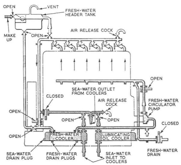
An auxiliary engine has to get rid of the heat that goes into the cylinder liners, the cylinder heads, the pistons, the lubricating oil and the charge air. It does it with two water circuits: a fresh water circuit round the engine, and a sea water circuit to take the heat away.
The simple closed circuit
A variety of cooling systems may be adopted for marine auxiliary engines, but the most commonly used is the simple closed circuit system.
The arrangement is:
- Sea water is passed through the intercooler, the oil cooler and then the jacket water cooler, in series flow. One sea water pump drives all three.
- Engine-driven fresh water circulating pumps are normally fitted, circulating the fresh water round the engine jackets.
- The sea water pump may be either an independent unit or engine driven in tandem with the fresh water pump.
There is an emergency provision worth knowing about: the cooling system may be arranged so that in an emergency, sea water can be circulated through the engine jackets, after removal of certain blanks installed in the pipework. The blanks are there to stop sea water reaching the jackets in normal operation; removing them lets the engine be cooled directly from the sea if the fresh water circuit is lost. Doing this is a last resort — sea water in the jackets means corrosion — but it will get the ship into port.
Cross-connections with the main engine
In ships with diesel main propulsion engines, cross-connections between the main and auxiliary engine jacket water systems are common. Two things are achieved:
- The main engine can be kept warm in port from the heat in the auxiliary engine jacket water. The auxiliary engine is running anyway, and its waste heat is exactly what the main engine needs to stay above the temperature at which acid condensation and thermal shock become a problem.
- To enable the auxiliary engine to be run in dry dock, it is customary to arrange a connection from a double bottom or peak tank. In dry dock there is no sea water available, so the cooling has to come from a tank inside the ship.
Jacket water temperature
The outlet temperature of the cooling water has to be maintained between about 78 and 82 °C.
That figure is not arbitrary. Too cold, and:
- Water will deposit on the liner surface, destroying the lubricating oil film.
- The liner runs below the dew point of the acids formed from the fuel's sulphur, and corrosive wear accelerates.
Too hot, and the coolant boils, the oil film breaks down, and the thermal load on the components becomes excessive.
The temperature is held by a thermostatically controlled three-way valve at the jacket cooler outlet, which mixes cooled and uncooled water to maintain the outlet temperature.
The central cooling system
Many modern installations use a central cooling system instead of a separate sea water circuit for each machine. In a central system:
- Only one heat exchanger is cooled by sea water — the central cooler. Every other cooler in the ship is cooled by the central fresh water circuit.
- The low temperature and high temperature systems are directly connected, to gain the advantage of preheating the main engine and generating sets during standstill.
- Because all the fresh cooling water is inhibited and common, only one common expansion tank is necessary, for deaeration of both the low and high temperature systems. That tank accommodates the difference in water volume caused by temperature changes.
- To prevent the accumulation of air in the cooling water system, a deaerating tank is located below the expansion tank.
- An alarm device is inserted between the deaerating tank and the expansion tank, so that the crew are warned if excess air or gas is released — because this signals a malfunction of engine components. A cooling system that starts giving off gas is telling you something is leaking into it.
Operation at sea: the sea water cooling pump supplies sea water from the sea chests through the central cooler and overboard. On the fresh water side, the central cooling water pump circulates the low temperature fresh water directly through the lubricating oil cooler of the main engine, the generating sets and the scavenge air coolers. The jacket water cooling system for the generating sets runs at the higher temperature, separately.
The jacket water pump
For the purpose of jacket cooling, the auxiliary engines are provided with mechanical pumps. The jacket water pump can be driven electrically or by the engine.
Water transported using the jacket water pump should be clean, without any solid particles. The pump is a centrifugal machine, and solids in the water will destroy the impeller and the seal.
The cooling water header tank
The cooling water header, or expansion, tank is one of the tanks checked before every start. It does two jobs: it lets the water expand and contract with temperature without the system losing water, and it provides the head that keeps the pump suction flooded. Header tank levels must be monitored — a falling level is a leak, and a rising level can mean a leaking cooler putting sea water into the fresh water system.
2. The lubricating oil system
What the oil has to do
An engine lubricating oil system performs four functions:
- Lubrication — it forms a film between moving parts, reducing friction, wear and tear.
- Cleaning — it acts as a cleaning agent by taking dirt and debris away from the running surfaces.
- Cooling — it acts as a coolant and maintains the temperature of the moving parts within tolerable limits. On an auxiliary engine this is a large part of the oil's job, because the pistons are oil cooled.
- Hydraulic activation — it acts as the activating medium on engines provided with hydraulically actuated exhaust valves.
On an auxiliary engine the cooling duty is the one that is easy to forget. The oil is not only a film between surfaces; it is the medium that carries heat out of the piston crown.
The circuit
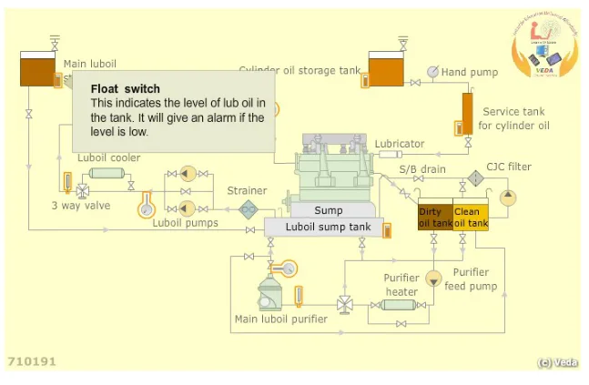
The system consists of:
- Storage tanks for holding lubricating oil.
- The engine sump, which receives oil from the storage tank. On a medium-speed engine the sump is the bedplate itself, and a dipstick is provided to ascertain the level.
- The main lubricating oil supply pump, which draws suction from the sump through a suction strainer.
- The discharge filters and the oil cooler.
- The distribution pipework, leading oil to the bearings and the piston cooling spaces.
- The purifier, which draws oil from the sump and returns it after purification.
The lubricating oil pump is a gear type or trochoidal pump. It is driven from the end of the crankshaft through a claw coupling, or through a flexible gear wheel connection — which is why the crankshaft has a claw coupling at each end. It discharges oil to the main bearings, the connecting rod bearings and the other running gear through a set of discharge filters.
The oil then follows the path described in Chapter 4: main gallery, main bearing, crankshaft drilling, big end bearing, connecting rod drilling, small end bush, piston cooling space, and out by the drain duct.
The purifier
The engine's lubricating oil is continuously purified during engine operation. The purification system consists of a purifier which draws lubricating oil from the sump and transfers it back to the sump after purification. The purifier removes water and solid contaminants. Proper monitoring and maintenance of this system ensures trouble-free operation.
The practical figures for an auxiliary engine's sump:
- The system oil volume should be centrifuged at least three times a day through the separator, operating at about 40 % throughput of its rated capacity. Running a purifier slowly is what makes it separate properly; running it at full throughput just passes the dirt through.
- The water content of the lubricating oil should not exceed 0.5 % by mass over an extended period. If higher contamination is observed, intensified treatment in the separator, or a renovating tank, must be considered.
Monitoring the sump level
Monitoring the lubricating oil sump level is an important part of the watchkeeper's duty.
The level of oil indicated in the sump when the engine is running must be sufficient according to the maker's and shipbuilder's instructions. The "sump quantity" is always maintained at the same safe operating level, and is given in litres. It is essential that the figures are steady and correct, taking account of consumption, losses and refills.
Any increase or decrease — except a marginal decrease — could be due to a problem, and would have serious implications. The two directions mean different things:
- A falling level means the oil is going somewhere: out through a leak, past the piston rings into the combustion space, or into the cooling water through a failed cooler.
- A rising level means something is coming in: water from a leaking liner O ring or a leaking cooler, or fuel from a leaking injector. A rising sump level is the more dangerous of the two, because the oil is being diluted while it is still being relied on.
Batch purification
When the oil has become contaminated and the running purifier cannot keep up, batch purification is carried out:
- Allow the oil to settle for about 24 hours at around 60 °C.
- Drain sludge and water periodically from the tank.
- Clean the sump thoroughly and examine it.
- Purify the oil at optimum efficiency, proper temperature and minimum throughput.
- Return the purified oil to the sump tank.
Where a source of water has been found and rectified, the sequence is more thorough: find and rectify the source of the seawater leak immediately, transfer the whole sump oil to the lubricating oil settling tank, maintain the temperature at around 60 °C, drain water and sludge periodically, clean and inspect the sump, and renew the sump with fresh lubricating oil.
Lubricating oil samples should be sent for shore analysis, and the report will specify whether the oil can be reused, or whether treatment such as water washing is needed.
Why an auxiliary engine's oil is treated differently from a main engine's
There is one practical difference worth noting. The separator for an alternator prime mover is operated from time to time, whereas for a main propulsion engine sump the purifier is invariably started on sump-to-sump mode at least four hours before engine operation, to remove accumulated dirt or settled water.
The reason is that a main engine runs continuously for weeks and accumulates contamination continuously, while an auxiliary engine's running hours are shorter and more intermittent. But the auxiliary engine still needs its oil clean, and the purifier still has to be run — just not on the same schedule.
Cylinder lubrication — a difference from the main engine
Slow speed diesel engines have a separate lubrication system for the cylinder liners, because the fuel burnt in the combustion space is high in sulphur content, and this results in acidic corrosion of the liners due to the formation of dilute sulphuric acid. To prevent this, a special lubricating oil is used, which also contains additives to keep the liner clean. In that system, mechanical lubricators supply oil to individual cylinders, injecting cylinder oil between the liner and the piston rings during the upward stroke.
An auxiliary engine does not have this. Being a trunk piston engine, the cylinder is lubricated from the crankcase by the same oil that lubricates the bearings, and the oil's alkalinity — its TBN — is chosen to neutralise the acid formed from the fuel being burned. This is the reason the oil specification for an auxiliary engine is tied to the fuel it runs on, and why an engine switched to heavy fuel needs an oil of higher TBN.
3. The fuel system
What the engine needs
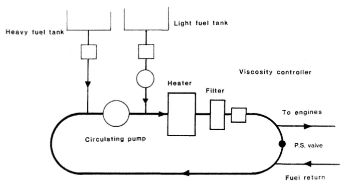
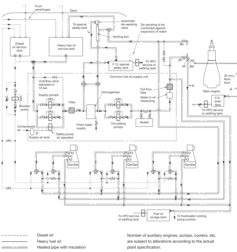
The fuel system has to deliver clean, correctly treated fuel to the injection pumps at the right pressure, temperature and viscosity. On an auxiliary engine this is complicated by the fact that the engine may be asked to run on distillate, residual fuel, or a blend of the two.
Diesel oil system components: bunker tanks, engine room settling and service tanks, transfer pumps, strainers, full flow filters, a viscosity regulator and purifiers.
Heavy fuel oil system components: the same, plus heaters and a fuel oil circulating pump.
Fuel changeover
Changeover from heavy fuel oil to diesel oil is necessary if the vessel is expected to have:
- A prolonged inactive period with a cold engine.
- A major repair of the fuel oil system.
- A drydock.
- A long lay-up of the vessel.
In each case the reason is the same: heavy fuel has to be kept hot to flow and to atomise, and if the heating is going to be off, the heavy fuel has to be out of the system first. Heavy fuel left cold in a pipe sets solid.
The changeover is made gradually, with the fuel temperature and viscosity monitored, because the fuel pump's plunger and barrel clearances depend on the fuel's viscosity for their sealing. Change too fast and the engine either loses power or the pump seizes.
Continuous circulation of heavy oil is necessary even when the engine is stopped. This is to keep the fuel oil system components — fuel pumps, pipes and valves — at service temperature, so that the engine can be started and loaded without waiting for the whole system to heat up.
The fuel blender
Burning residual fuel in a medium-speed auxiliary engine is done to save money, and the fuel blender is the device that lets it be done gradually.
Conventionally, the lower cost residual fuels are used for large slow-speed diesel main engines, and generators are operated on the lighter, more expensive distillate fuel. The addition of a small amount of residual fuel to the distillate, as the load increases, gives cost savings without asking the engine to cope with heavy fuel from cold.
Blenders improve fuel economy, but running hours still mount up, and routine maintenance is likely to be increased by the use of poor quality residual fuels. That is the trade: cheaper fuel, more maintenance.
Fuel treatment
Because the fuel may contain catalytic fines — abrasive particles based on aluminium and silicon — and other solids, treatment is essential:
- Purification of fuels is necessary to remove solids.
- Where catalytic fines are suspected, the use of centrifuges arranged as two purifiers in parallel, or a purifier and a clarifier in series, is recommended.
The reason for the two arrangements is that a purifier removes water and solids by centrifugal separation with a water seal, while a clarifier removes solids only, without a water seal. Running them in series gets the best of both; running two purifiers in parallel doubles the throughput for the same separation quality.
Serious damage by corrosion or erosion will finally require renewal of parts, if the efficiency of the turbocharger and the diesel is to be maintained.
Fuel-side damage from the fuel's own chemistry
Where the engine burns residual fuel, the fuel contains vanadium, sodium and sulphur as impurities, and the engine operates in a marine environment where sodium chloride is present in the intake air. The impurities burn to form a number of different ash products, which may adhere to surfaces at higher temperatures. Corrosion and surface damage follow breakdown of the protective film on the metal surface by ash compounds.
The remedies are based on designing for lower operating temperatures, and regular water washing to remove the accumulated slag.
Erosion by solids entrained in the exhaust gas is a second problem. Catalytic fines, being abrasive, will be present in some fuels and could cause surface damage to nozzles.
Water in the fuel
Some installations deliberately add water to the fuel. A system for the emulsification of water into the fuel is fitted on some engines, common to the main engine and the generating sets. The water is emulsified into the fuel and flashes to steam in the cylinder, which improves combustion and reduces nitrogen oxide formation. The emulsification has to be carefully controlled, because too much water means the engine will not fire.
Fuel quality
The governing rule is short: the fuel should conform to the specification given in the instruction book for the engine. Fuels bunkered for a slow-speed main engine may be of too poor a quality for an auxiliary even where the engine has been designed for heavy fuel operation, and major problems have been experienced with poor quality bunkers. The engine's own specification is the only reliable guide.
4. The tanks and levels checked before starting
The pre-operation check list names the tanks and levels that must be confirmed before an auxiliary engine is started. They are worth listing, because each one corresponds to a system above:
- Cooling water header tank.
- Oil sump tank.
- Cylinder lubricating oil tank, if provided.
- Fuel service and settling tank.
- Diesel storage tanks.
- Turbocharger oil level.
- Governor oil level.
- Outboard bearing oil level.
- Air pressure for the 30 bar and 8 bar tanks.
Two of these are easy to overlook and both matter. The governor oil level — because a hydraulic governor with low oil will not control the engine. And the outboard bearing oil level — because the bearing carrying the alternator end of the shaft is lubricated separately from the engine on many sets, and it is not visible from the engine itself.
The jacket water and injector cooling water expansion tanks must also be checked for proper level and that the pumps are in operation, and the inlet and outlet valves of the nozzle and jacket water systems checked for correct open or closed position before the heaters are energised.