
Purifier Automatic Control and Instrumentation
How do the automatic panel, timers, solenoid valves, detectors, and displays coordinate purifier operation?
Key Principles at a Glance 8 points
- Automation exists because manual valve operation would be too slow and too vulnerable to timing error — the panel sequences the same operations every cycle.
- The control panel drives solenoid valves, and the solenoid-valve unit switches the operating water that opens, closes and seals the bowl.
- Timers control the cycle — discharge interval, opening and closing times, and lubricating-oil bowl washing — and their settings depend on operating-water flow and contamination load.
- Interlocks prevent unsafe sequencing, for example admitting feed before the bowl is closed or discharging while the bowl is not at speed.
- The Multi-Monitor system supervises the machine through the Leakage Monitor, Discharge Detector and Water Detector, and raises alarms on abnormal seal, discharge or water carry-over.
- Auto-stop and emergency-stop logic shut the machine down on defined conditions, and understanding that logic is how a control fault is separated from a mechanical one.
- Control faults appear as a valve that will not change, a solenoid that will not operate, a false leakage alarm, a no-discharge alarm or a water alarm — each points to a specific sensor or valve.
- Manual mode is for testing and fault-finding; automatic mode is normal running.
1. Learning objectives
Course position: Topic 15 of the purifier learning sequence
Main question: How do the automatic panel, timers, solenoid valves, detectors, and displays coordinate purifier operation?
After studying this lesson, you should be able to:
- Identify the functions of an automatic purifier-control panel.
- Explain AUTO START, AUTO STOP, EMERGENCY STOP, and DISCHARGE TEST.
- Explain how timers sequence solenoid valves.
- Describe total-discharge and partial-discharge control.
- Explain the Multi-Monitor.
- Explain Leakage Monitor, Discharge Detector, and Water Detector functions.
- Interpret current, speed, pressure, temperature, and alarm indications.
- Explain why timer values depend on operating-water flow.
- Describe safe adjustment of discharge quantity and outlet pressure.
- Diagnose common automatic-control faults.
- Answer an examination question on purifier automation.
2. Why automation is required
A self-cleaning purifier must perform several actions in a definite order:
- Run the bowl at rated speed.
- Establish a water seal.
- Admit feed liquid.
- Control clean-oil and water outlets.
- Stop feed before discharge.
- Supply replacement water.
- Open the bowl hydraulically.
- Discharge sludge or separated water.
- Close the bowl.
- Restore the seal.
- Monitor the result.
Manual operation of every valve would be slow and vulnerable to timing errors. The automatic panel coordinates these operations through timers, relays, solenoids, sensors, and interlocks.
The automatic panel contains timers that control solenoid valves and other actions. Correct timer settings are essential for normal operation.
3. Main automatic-control components
A typical system includes:
- Starter panel
- Automatic control panel
- Multi-Monitor
- Motor starter
- Feed valve
- Gear pump
- Oil heater
- Flow-control valve
- Back-pressure or pressure-control valve
- Operating-water solenoid-valve unit
- Air filter-regulators
- Pressure gauges
- Temperature indicator
- Speed sensor
- Leakage Monitor
- Discharge Detector
- Water Detector
- Alarm reset
- Graphic or operation display
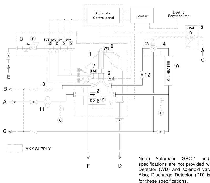
The exact equipment depends on purifier model and control-panel type.
4. Automatic control panel buttons
AUTO START
AUTO START begins the predetermined running sequence after the purifier reaches rated speed.
A typical sequence is:
AUTO STOP
AUTO STOP:
- Switches the feed valve to bypass or closes feed.
- Performs replacement-water and sludge-discharge operations.
- Cuts the automatic-running circuit.
- Stops the purifier motor.
EMERGENCY STOP
EMERGENCY STOP:
- Cuts the automatic-running circuit immediately.
- Switches the feed valve to bypass.
- Stops the motor without waiting for normal sludge discharge where configured.
DISCHARGE TEST
DISCHARGE TEST forces the discharge interval timer to time up while the purifier is feeding, allowing a discharge sequence to be tested.
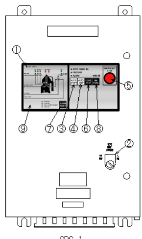
These functions are described in the Mitsubishi control-panel documentation.
5. Normal automatic-running sequence
The controller must prevent incompatible valves from opening at the wrong time.
For example:
- Feed should not continue during a full sludge discharge.
- Bowl opening water should not be applied as normal closing water.
- Clean-oil routing must remain safe during discharge.
- Alarm outputs must correspond to actual sequence states.
6. Solenoid-valve unit
The operating-water solenoid unit controls:
- Water for opening the bowl
- Water for closing the bowl
- Sealing water
- Replacement water
- Regulating water in applicable systems
The unit receives electrical signals from the automatic panel and starts or stops water flow to the purifier.
Total-discharge unit
A total-discharge system may use a triple-solenoid arrangement.
Total and partial-discharge unit
A system capable of both modes may use a quadruple-solenoid arrangement.
The number and valve labels are model-specific.
7. Timer-controlled operations
Timers determine the duration or interval of actions such as:
- Feed-liquid running period
- Sealing-water supply
- Replacement-water supply
- Opening-bowl water
- Closing-bowl water
- Partial-discharge water
- Bowl-washing water
- Intermittent water supply
- Discharge interval
- Detector reset
- Alarm monitoring delay
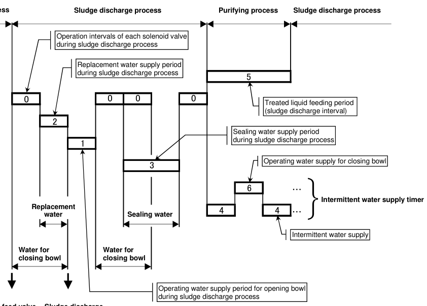
Timer categories
| Timer type | Function |
|---|---|
| Interval timer | Determines when discharge occurs |
| Pulse timer | Determines valve-on duration |
| Delay timer | Allows pressure or speed to stabilise |
| Counter | Counts discharge or washing events |
| Monitoring timer | Defines alarm confirmation period |
8. Why timer settings depend on water flow
A timer does not directly guarantee a water quantity. The actual quantity depends on:
where:
- Q = water quantity
- q = actual flow rate
- t = valve-open time
If operating-water flow changes, the same timer produces a different quantity.
The manufacturer states that standard timer settings are guidelines based on specified flow rates and that actual flow should be measured for practical settings.
Do not copy timer values from a different purifier model without checking flow conditions.
9. GSH-1 timer setting example
The GSH-1 guideline includes timers for:
- Interval
- Opening bowl
- Replacement water
- Regulating water
- Bowl-washing water
- Partial opening
- Partial replacement water
- Intermittent water supply
- Closing bowl
- Discharge interval
- Detector reset
- Water-detection counter
- Monitoring time
- Lubricating-oil washing counter
The values differ with purifier size and are not universal operating settings.
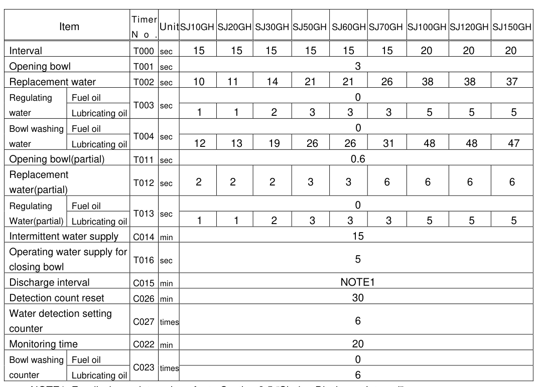
Fuel-oil difference
The GSH-1 guidance states that fuel-oil purifiers do not use regulating-water and bowl-washing processes in the same way as lubricating-oil operation.
Lubricating-oil difference
Lubricating-oil treatment may add:
- Regulating water
- Bowl washing
- Washing counters
- More complex discharge sequences
Always select the timer table for the actual oil and operating mode.
10. Total-discharge control sequence
A typical total-discharge sequence is:
Total discharge removes the bowl contents, including sludge and liquid.
The exact sequence and timer labels vary by model.
11. Partial-discharge control sequence
A partial-discharge sequence removes sludge or separated water without emptying the full bowl contents.
Partial discharge requires accurate opening-water quantity and timing.
Too little water may produce incomplete discharge.
Too much water may produce excessive discharge and oil loss.
12. Lubricating-oil bowl washing control
For lubricating-oil operation, washing may be added after sludge discharge.
The manual states that lubricating-oil washing is controlled by the washing counter and is added after the sludge-discharge process.
Failure to wash at the required interval may cause deposits, lower performance, and mechanical trouble.
13. Multi-Monitor system
The Multi-Monitor is an integrated display and detection system.
Depending on model, it may display:
- Flow rate
- Temperature
- Pressure
- Rotation speed
- Alarm status
- Leakage status
- Discharge status
- Water-detection status
Available Multi-Monitor configurations differ. The manuals identify MM-1, MM-2, and MM-3 variations with different detector functions.
14. Leakage Monitor function
The Leakage Monitor detects a pressure drop at the light-liquid outlet caused by leakage.
A pressure sensor at the light-liquid outlet sends a signal through the Multi-Monitor to the automatic panel.
Possible leakage causes
- Bowl not fully closed
- Main seal ring damaged
- Operating-water leakage
- Incorrect outlet pressure
- Oil escaping toward the sludge outlet
- Wrong hydraulic sequence
Monitoring logic
Pressure must be adjusted correctly before relying on the Leakage Monitor.
15. Discharge Detector function
The Discharge Detector monitors whether sludge discharge occurred.
During normal discharge, horizontal-shaft speed drops to a preset level because discharge creates a temporary load or torque change. A proximity sensor detects the speed change.
No-discharge alarm
If the expected speed change does not occur, the system may indicate:
- No discharge
- Incomplete discharge
- Bowl failed to open
- Sensor fault
- Incorrect detector setting
Do not treat a no-discharge alarm as merely an electrical nuisance. Confirm the actual bowl condition.
16. Water Detector function
The Water Detector identifies water entering an unexpected outlet or condition.
It may be used to detect:
- Water contamination
- Incorrect interface condition
- Leakage path
- Fault in bowl closure
- Incorrect water sequence
The Water Detector function is associated with certain Multi-Monitor configurations and may not be fitted to every automatic panel.
Water-detector caution
For some total-discharge arrangements, the water-detector selector must be set appropriately because the operating mode affects expected water flow.
Never disable a detector without following the maker’s documented procedure.
17. Control-panel indicators
Typical indicators include:
- Continuous power lamp
- Power switch status
- Auto-start status
- Auto-stop status
- Emergency-stop status
- Discharge-test status
- Alarm reset
- Multi-Monitor function status
- Graphic panel
- Operation display
- Rotation indicator
- Leakage alarm
- Discharge alarm
- Water alarm
The operator should interpret indicators together with physical evidence:
- Current change
- Discharge sound
- Pressure movement
- Speed movement
- Flow
- Actual outlet condition
A lamp alone does not prove that a hydraulic action occurred.
18. Startup logic and interlocks
A typical automated startup requires:
- Correct valve lineup.
- Operating water available.
- Air pressure available.
- Gear-case oil correct.
- Bowl correctly assembled.
- Brake released.
- Power applied in correct order.
- Motor started.
- Rated speed reached.
- Automatic sequence enabled.
The manual requires power switches to be turned on in the specified order for starter, automatic panel, and Multi-Monitor.
Why interlocks matter
Interlocks prevent:
- Feeding before rated speed
- Opening the bowl during normal feeding
- Starting with an active emergency stop
- Operating with unavailable water
- Continuing after a critical alarm
19. Auto-stop logic
When AUTO STOP is pressed:
The discharge should be confirmed by current increase/change and discharge sound where the manual specifies.
Do not close valves manually before the automatic sequence reaches the required state.
20. Emergency-stop logic
When EMERGENCY STOP is pressed:
Emergency stop prioritises rapid removal of danger over bowl cleaning.
Use it for:
- Excessive vibration
- Contact sound
- Abnormal bearing sound
- Dangerous mechanical failure
- Electrical emergency
21. Discharge-test operation
DISCHARGE TEST is used to test discharge while the purifier is in automatic running and feeding.
Typical procedure:
- Confirm the purifier is stable at rated speed.
- Confirm feed and water conditions.
- Press DISCHARGE TEST.
- Observe the sequence.
- Confirm discharge sound and current change.
- Observe detector or LED indication.
- Measure discharge quantity where required.
- Return to normal automatic operation.
The discharge-test function forces the interval timer to time up.
Do not repeatedly test discharge with the machine in an unstable condition.
22. Adjusting discharge quantity
For systems with a partial-discharge adjustment, the operating-water tank pressure or regulating pressure may affect quantity.
A typical adjustment procedure is:
The manual describes LED indications such as:
- Red: over
- Green: just
- Red: under
If the setting is changed, another discharge test should be performed after line pressure stabilises.
Do not adjust pressure and timer simultaneously.
23. Light-liquid outlet pressure adjustment
The Leakage Monitor requires the light-liquid outlet pressure to be adjusted to the preset level in the Multi-Monitor.
Typical steps include:
- Complete pre-operational checks.
- Switch on starter, automatic panel, and Multi-Monitor.
- Set the Multi-Monitor function switch appropriately.
- Disable alarm output only as required during adjustment.
- Adjust the back-pressure control valve.
- Stabilise feed rate and temperature.
- Confirm pressure at the required level.
- Restore alarm output.
The manual warns that flow and temperature fluctuations affect light-liquid outlet pressure and may affect Leakage Monitor output.
24. Timer-setting rules
Rule 1 — Use the correct table
Timer tables differ for:
- Purifier model
- Total-discharge mode
- Partial-discharge mode
- Fuel oil
- Lubricating oil
- Bowl size
- Control-panel type
Rule 2 — Measure actual flow
Standard values are guidelines. Actual operating-water flow should be measured.
Rule 3 — Change one variable at a time
If timer and pressure are changed together, the result cannot be attributed reliably.
Rule 4 — Record original values
Before adjustment, record:
- Timer number
- Original value
- New value
- Reason
- Date
- Operator
- Result
Rule 5 — Test after adjustment
Confirm:
- Bowl opening
- Bowl closing
- Discharge quantity
- Seal restoration
- Alarm response
- No oil loss
25. Automatic-control fault: feed valve does not change
Causes
- Air pressure low
- 3-way cylinder valve fault
- Solenoid not energised
- Control-panel output fault
- Valve mechanically stuck
- Incorrect mode
- Interlock active
Checks
- Confirm command appears on panel.
- Check air filter-regulator.
- Check valve actuator movement.
- Check solenoid coil and wiring.
- Confirm valve position.
- Check whether an alarm or interlock blocks operation.
Do not force the feed valve while the controller is commanding an incompatible state.
26. Automatic-control fault: solenoid valve does not operate
Possible causes
- No electrical output
- Coil failure
- Sticking valve spool
- Blocked pilot passage
- Low air or water pressure
- Strainer blockage
- Incorrect timer setting
- Loose connector
Diagnosis
Separate electrical failure from hydraulic restriction before replacing parts.
27. Automatic-control fault: false leakage alarm
Possible causes
- Light-liquid pressure too low
- Feed-rate fluctuation
- Temperature fluctuation
- Actual bowl leakage
- Pressure sensor fault
- Incorrect delay setting
- Alarm output left enabled during adjustment
The manual notes that pressure and temperature fluctuations can affect Leakage Monitor output.
Correct response
- Check actual outlet pressure.
- Check feed and temperature stability.
- Confirm bowl closure and seals.
- Check sensor and wiring.
- Do not simply disable the alarm permanently.
28. Automatic-control fault: no-discharge alarm
Possible causes
- Bowl did not open
- Discharge quantity too low to produce expected speed change
- Discharge interval not reached
- Proximity sensor misaligned
- Sensor wiring fault
- Horizontal-shaft speed already unstable
- Sludge hardened in ports
Checks
- Confirm discharge command.
- Confirm opening-water pressure.
- Observe current and sound.
- Check proximity sensor.
- Inspect actual sludge remaining after isolation.
29. Automatic-control fault: water alarm
Possible causes
- Actual water contamination
- Incorrect detector selector
- Water sequence incorrect
- Excess sealing water
- Faulty sensor
- Dirty detector
- Operating mode mismatch
Fuel-oil and lubricating-oil modes may use different regulating and washing processes. Ensure the control panel is configured for the correct liquid and mode.
30. Manual mode and automatic mode
Automatic mode
Advantages:
- Repeatable sequence
- Reduced operator workload
- Integrated alarms
- Automatic discharge
- Detector feedback
Risks:
- Incorrect timer setting affects every cycle.
- A failed sensor can mislead the controller.
- Operators may trust lamps without checking the machine.
Manual mode
Advantages:
- Useful for commissioning and diagnosis
- Allows individual valve testing
- Helps confirm water paths
Risks:
- Wrong valve order can damage the process.
- Feed may continue during an unsafe action.
- Operator may bypass an interlock.
Manual mode must be used only by authorised personnel following the maker’s sequence.
31. Operating data and trend monitoring
Record automatic-control data such as:
- Discharge count
- No-discharge alarms
- Leakage alarms
- Water alarms
- Bowl-washing count
- Feed rate
- Temperature
- Outlet pressure
- Speed
- Current
- Timer changes
Trend interpretation
| Trend | Possible meaning |
|---|---|
| Increasing no-discharge alarms | Hydraulic restriction, sludge blockage, sensor problem |
| Increasing leakage alarms | Seal wear, pressure instability, bowl closure fault |
| Increasing current | Mechanical drag, sludge, pump load, bearing wear |
| Falling speed | Clutch, motor, bearing, or overload problem |
| More frequent water alarms | Interface, water flow, seal, or detector problem |
32. Control sequence diagram
Detector feedback may interrupt this normal path and generate an alarm.
33. Automatic-panel operating checklist
Before start
- [ ] Correct operating mode selected.
- [ ] Correct gravity disc fitted.
- [ ] Correct timer table selected.
- [ ] Timer values recorded.
- [ ] Operating-water pressure correct.
- [ ] Air pressure correct.
- [ ] Feed and outlet valves aligned.
- [ ] Multi-Monitor powered.
- [ ] Emergency stop reset.
- [ ] Alarm outputs in correct state.
During running
- [ ] Rated speed stable.
- [ ] Current normal.
- [ ] Temperature stable.
- [ ] Feed rate stable.
- [ ] Outlet pressure stable.
- [ ] No leakage alarm.
- [ ] No water alarm.
- [ ] Discharge confirmation normal.
- [ ] Vibration and sound normal.
During discharge test
- [ ] Feed condition stable.
- [ ] Discharge test authorised.
- [ ] Current change observed.
- [ ] Discharge sound observed.
- [ ] Detector response observed.
- [ ] Quantity measured if required.
- [ ] Adjustment recorded.
34. Automation troubleshooting checklist
- [ ] Confirm the command was actually given.
- [ ] Check control-panel power.
- [ ] Check starter power.
- [ ] Check Multi-Monitor power.
- [ ] Check emergency-stop status.
- [ ] Check mode switch.
- [ ] Check air pressure.
- [ ] Check operating-water pressure.
- [ ] Check solenoid output.
- [ ] Check timer value.
- [ ] Check valve movement.
- [ ] Check sensor signal.
- [ ] Check actual machine response.
- [ ] Compare alarm indication with physical evidence.
- [ ] Record and restore any temporary adjustment.
35. Revision questions with answers
Question 1
What does AUTO START do?
Answer: It initiates the predetermined automatic-running sequence after rated speed is reached.
Question 2
What does AUTO STOP do?
Answer: It bypasses or stops feed, performs replacement and sludge discharge, and stops the motor.
Question 3
How does EMERGENCY STOP differ from AUTO STOP?
Answer: Emergency stop cuts the automatic circuit immediately and may stop without normal sludge discharge.
Question 4
What does DISCHARGE TEST do?
Answer: It forces the discharge interval timer to time up so a discharge can be tested.
Question 5
Name four water-control functions.
Answer: Opening water, closing water, sealing water, and replacement water.
Question 6
Why do timer values depend on water flow?
Answer: The delivered quantity equals actual flow multiplied by valve-open time.
Question 7
What does the Leakage Monitor detect?
Answer: A pressure drop at the light-liquid outlet associated with leakage.
Question 8
How does the Discharge Detector confirm discharge?
Answer: It detects the characteristic horizontal-shaft speed change during discharge.
Question 9
What does the Multi-Monitor display?
Answer: Depending on type, flow, temperature, pressure, speed, leakage, discharge, and water status.
Question 10
Why must timer adjustments be recorded?
Answer: To preserve the original setting, identify the change, and allow controlled troubleshooting.
Question 11
Why should actual water flow be measured?
Answer: Standard timer settings are based on guideline flow rates and may not suit actual conditions.
Question 12
What should be checked when a no-discharge alarm occurs?
Answer: Command, water pressure, solenoid, timer, sensor, actual bowl opening, and remaining sludge.
36. Self-test scenarios
Scenario A — no-discharge alarm
The controller commands discharge, but the detector indicates no discharge.
Correct approach:
- Confirm the command.
- Check operating-water pressure.
- Check opening solenoid and strainer.
- Check proximity sensor.
- Observe current and discharge sound.
- Inspect the bowl after safe isolation.
Scenario B — repeated leakage alarm after a timer change
Correct approach:
- Restore or record the original timer value.
- Check actual light-liquid outlet pressure.
- Stabilise feed rate and temperature.
- Check bowl closure and seals.
- Confirm alarm delay and sensor condition.
- Make only one controlled adjustment.
Scenario C — discharge quantity too high
Correct approach:
- Stop unnecessary repeated testing.
- Measure actual quantity.
- Check operating-water pressure.
- Adjust reducing-valve pressure according to the manual.
- Wait for pressure stabilisation.
- Repeat one discharge test.
- Confirm detector indication and oil loss.