
Three-Phase Flow Through the Purifier Bowl
How do oil, water, and solids travel through the bowl from inlet to separate outlets?
Key Principles at a Glance 8 points
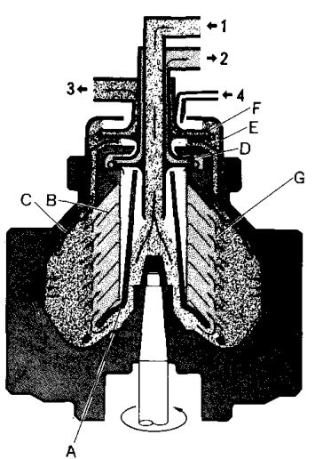
- Three phases leave by three routes: oil inward to the light-liquid outlet, water outward to the heavy-liquid outlet, and solids outward to the sludge space at the bowl wall.
- Feed enters at the centre, is accelerated by the distributor, and is thrown out to the outer edge of the disc stack.
- Between the discs the flow is shallow and laminar: oil travels inward along the upper surface of each disc while water and solids travel outward along the lower surface.
- The oil-water interface is the boundary between the inward and outward liquid paths, and its position decides the purity of both outlets.
- Sealing water must be in place before oil feed — it forms the initial interface and stops oil escaping to the water outlet.
- Light-liquid and heavy-liquid outlet pressures are balanced by the impellers, and a wrong balance sends one phase out of the wrong outlet.
- Higher viscosity or a higher feed rate distorts the phase paths and reduces how completely the phases separate.
- During sludge discharge the bowl opens, the sludge space empties, and the seal has to be re-established before purification continues.
1. Learning objectives
Course position: Topic 6 of the purifier learning sequence
Main question: How do oil, water, and solids travel through the bowl from inlet to separate outlets?
After studying this lesson, you should be able to:
- Define three-phase purifier operation.
- Trace feed oil from the inlet to the distributor.
- Explain how the distributor feeds the disc stack.
- Trace the separate paths of oil, water, and solids.
- Explain the purpose of the interface.
- Explain how sealing water establishes the correct liquid arrangement.
- Explain the functions of the light-liquid and heavy-liquid outlets.
- Compare purifier flow with clarifier flow.
- Explain how changes in density and feed rate affect the flow paths.
- Diagnose common outlet and interface problems from the flow pattern.
2. The complete three-phase idea
A purifier receives one mixed feed and produces three controlled outputs:
The three phases are:
- Light liquid: oil
- Heavy liquid: water
- Solid phase: dirt, sludge, rust, catalyst fines, and wear particles
The Mitsubishi manual calls this three-phase liquid-liquid-solid separation.
A purifier does not simply send “dirty material” to one waste outlet. Each phase follows a different path inside the rotating bowl.
3. The flow map
The main flow rule is:
Oil moves inward, water moves outward, and solids move outward to the bowl wall.
The manufacturer’s purifier-bowl diagram identifies the feed-liquid inlet, light-liquid outlet, heavy-liquid outlet, sealing-water inlet, distributor, discs, top disc, impellers, gravity disc, and interface.
4. Phase 1: feed liquid enters
The feed liquid is untreated oil containing some combination of:
- Oil
- Water
- Solids
- Sludge
- Air or entrained gas, if the system is faulty
The feed enters through the feed-liquid inlet.
Before entry
The feed should normally have:
- Correct temperature
- Correct pressure
- Correct feed rate
- No excessive air leakage
- A suitable oil condition
- Correct valve alignment
If feed conditions are wrong, the bowl may be mechanically healthy but still produce poor separation.
Feed-liquid path
The feed must enter the correct location. A restriction or incorrect connection can reduce the effective capacity of the purifier.
5. Phase 2: the distributor accelerates the feed
The distributor receives the incoming feed and brings it close to bowl speed.
Reed’s states that radial vanes in the distributor rapidly bring the oil up to the rotational speed of the purifier.
Why this is required
The bowl is already rotating rapidly. If stationary oil entered directly into the rotating separation chamber:
- Relative velocity would be high.
- Turbulence would increase.
- The phase boundary could be disturbed.
- Separation would become less efficient.
- Mechanical energy would be wasted.
The distributor therefore provides a transition:
Distributor outlet
After acceleration, the oil moves through the lower bowl passages and distribution holes toward the disc stack.
The distributor does not separate the phases completely. It prepares the feed for the separation chamber.
6. Phase 3: feed enters the disc stack
The feed is directed to the outer region of the disc stack.
This arrangement is important because the separation process depends on radial movement:
- Heavy water must have a path outward.
- Solids must have a path outward.
- Light oil must have a path inward.
The Mitsubishi manual states that feed liquid passes through the distributor and is fed to the outer periphery of the discs.
7. What happens between the discs
The disc stack divides the separation chamber into many narrow passages.
Inside those passages:
- Oil follows the liquid-flow path toward the inner region.
- Water experiences an outward centrifugal tendency.
- Solids experience an even stronger outward tendency because of their density.
- Solids reach disc surfaces and move toward the bowl wall.
Reed’s describes water and sludge moving radially outward along the underside of discs while purified oil moves radially inward over the upper surfaces of the discs.
Separation is not instantaneous
The liquid does not separate at one single point. Separation develops progressively as the material moves through the disc stack.
The quality of this process depends on:
- Temperature
- Viscosity
- Density difference
- Bowl speed
- Disc condition
- Feed rate
- Correct interface position
8. Oil path: light liquid moves inward
Oil is normally lighter than water and heavy solids. Under the rotating-bowl conditions, the purified oil occupies the inner region.
Oil path step by step
- Oil enters with the feed liquid.
- It passes through the distributor.
- It enters the disc stack at the outer region.
- Water and solids move away from it.
- Oil moves inward between the discs.
- Oil reaches the light-liquid chamber.
- The light-liquid impeller discharges it.
- Clean oil leaves through the light-liquid outlet.
The light-liquid impeller is a centripetal pump. It uses the rotating liquid’s energy to discharge the purified oil continuously.
What clean-oil quality tells you
The clean-oil outlet can reveal:
- Water carry-over
- Remaining solids
- Interface error
- Incorrect gravity-disc selection
- Excessive feed rate
- Incorrect temperature
- Disc-stack problems
9. Water path: heavy liquid moves outward
Water is normally heavier than oil. It moves outward under centrifugal action.
Water path step by step
- Water enters mixed with the feed oil.
- It passes through the distributor and disc stack.
- It moves outward relative to the oil.
- It reaches the outer heavy-liquid region.
- It passes outside the top disc.
- It passes through the gravity-disc region.
- The heavy-liquid impeller discharges it.
- Water leaves through the heavy-liquid outlet.
The Mitsubishi manual describes this exact path through the outside of the top disc, past the gravity disc, and out through the second impeller.
Water-outlet observations
A water outlet containing:
- Mostly water: likely normal.
- Excessive oil: possible interface or gravity-disc error.
- Very little flow: possible blockage, low water content, or hydraulic problem.
- Sludge: possible discharge or bowl-cleanliness issue.
10. Solid path: solids move to the bowl wall
Solid particles are normally denser than oil and move outward.
Solid path step by step
- Solids enter with the feed liquid.
- They move through the disc passages.
- Centrifugal force drives them outward.
- They may contact the underside of a disc.
- They migrate along the disc toward the outer region.
- They deposit on the bowl wall.
- They form a sludge layer.
- They are removed during manual or automatic discharge.
Reed’s explains that solids present in the oil deposit on the side of the rotating bowl, with heavier solids depositing nearer the lower or outer region and lighter solids farther along the flow.
11. The interface
The interface is the boundary between the light liquid and heavy liquid.
The interface must remain within a controlled region.
Why it matters
If the interface moves too far inward:
- Water may enter the light-liquid region.
- Clean oil may contain water.
If the interface moves too far outward:
- Oil may escape through the heavy-liquid outlet.
- Oil loss increases.
What controls it
The interface is influenced by:
- Oil specific gravity
- Water density
- Treating temperature
- Feed rate
- Outlet pressures
- Gravity-disc inside diameter
- Sealing-water condition
The Mitsubishi manual states that a gravity disc with a larger inside diameter moves the interface outward, while a smaller inside diameter moves it inward.
12. Sealing water before oil feed
The purifier must first be filled with sealing water before feed oil is introduced.
Purpose
Sealing water:
- Establishes the heavy-liquid region.
- Prevents oil from flowing through the heavy-liquid outlet.
- Helps create the correct starting interface.
- Prepares the bowl for three-phase operation.
The normal sequence is:
Reed’s specifies operating speed followed by fresh water for the water seal and then oil feed.
The Mitsubishi manual states that sealing water is supplied through the sealing-water inlet and accumulates at the bowl periphery before normal feed begins.
If sealing water is absent
- Oil may escape through the water outlet.
- The interface may not form.
- Separation may be unstable.
- Oil loss may occur.
13. Heavy-liquid and light-liquid outlet balance
The purifier does not separate phases only by force. The outlet arrangements must also maintain the correct hydraulic balance.
The light-liquid side includes:
- Inner oil region
- Light-liquid chamber
- Light-liquid impeller
- Clean-oil outlet
The heavy-liquid side includes:
- Outer water region
- Gravity-disc region
- Heavy-liquid chamber
- Heavy-liquid impeller
- Water outlet
A fault in one outlet can affect the other because both share the same internal interface.
14. Full purifier flow sequence
Start-up and flow
- Bowl is started.
- Bowl reaches operating speed.
- Sealing water is supplied.
- Water occupies the outer region.
- Feed oil enters the inlet.
- Distributor accelerates the oil.
- Feed reaches the disc-stack periphery.
- Water moves outward.
- Solids move outward.
- Oil moves inward.
- Oil reaches the light-liquid impeller.
- Water reaches the gravity-disc and heavy-liquid path.
- Clean oil leaves the light-liquid outlet.
- Water leaves the heavy-liquid outlet.
- Solids remain in the sludge space.
- Sludge is discharged at the correct interval.
15. Three phases at the outlet regions
The three phases must be separated before they reach their respective outlet regions.
The bowl does not necessarily discharge solids continuously with the liquid outlets. Solids normally accumulate until the self-cleaning or manual discharge operation.
16. Purifier versus clarifier flow
16.1 Purifier flow
In purifier operation:
- Feed contains oil, water, and solids.
- Sealing water is supplied.
- Water moves outward.
- Oil moves inward.
- Solids collect at the bowl wall.
- Oil and water have separate outlet paths.
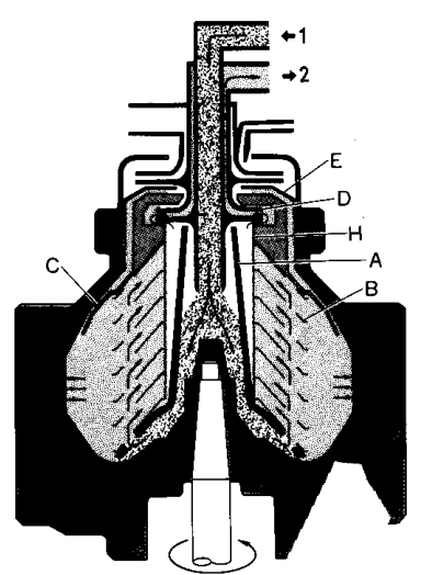
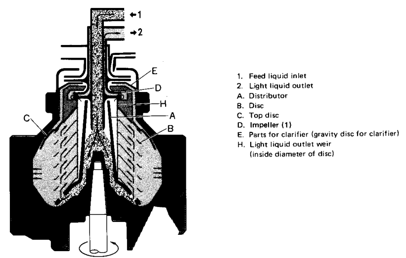
16.2 Clarifier flow
In clarifier operation:
- Feed contains oil and solids.
- Sealing water is not supplied in the same way.
- Solids move outward.
- Oil moves inward.
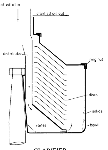
- Only the clarified oil is discharged as the liquid product.
- Solids collect on the bowl wall.
The Mitsubishi manual identifies clarifying operation as liquid-solid two-phase separation and states that sealing or replacement water is not supplied.
Comparison
| Flow feature | Purifier | Clarifier |
|---|---|---|
| Feed phases | Oil, water, solids | Oil and solids |
| Sealing water | Supplied | Not supplied in the same arrangement |
| Water outlet | Used | Not used for normal water separation |
| Oil outlet | Light-liquid outlet | Clarified-oil outlet |
| Solids | Bowl-wall sludge | Bowl-wall sludge |
| Interface | Oil-water interface | No normal oil-water interface |
17. Why the distributor feeds the outer disc region
The disc stack is designed so that separation develops as the material travels through the passages.
Feeding the outer region provides:
- Radial distance for water and solids to move outward.
- A path for clean oil to move inward.
- Contact between solids and disc surfaces.
- Proper use of the available separation area.
If feed enters the wrong location:
- Separation distance changes.
- Outlet contamination may occur.
- Flow may bypass the intended disc passages.
- The interface may become unstable.
This is why the distributor, disc-stack holes, and bowl passages must remain clean and correctly assembled.
18. Effect of viscosity on phase paths
High-viscosity oil resists movement of water droplets and solid particles.
Heating within the manufacturer’s limit reduces viscosity and improves the ability of the phases to move toward their correct regions.
However, heating does not correct:
- A wrong gravity disc
- A blocked outlet
- A damaged disc stack
- Incorrect bowl assembly
- A failed water seal
19. Effect of feed rate on phase paths
Feed rate controls residence time in the bowl.
Excessive feed rate
Lower feed rate
The correct feed rate also influences interface position and gravity-disc selection. If the feed rate or oil condition changes substantially, the purifier may require a new operating setting.
20. What happens when the interface is wrong?
Interface too far inward
The water region occupies too much of the inner bowl radius.
Possible results:
- Water enters the light-liquid path.
- Clean oil contains water.
- Clean-oil quality decreases.
- Water detector or alarm operates.
Interface too far outward
The oil region extends too far toward the water outlet.
Possible results:
- Oil leaves through the heavy-liquid outlet.
- Oil losses increase.
- Water outlet becomes oily.
- The purifier may appear to be “losing oil.”
Correct interface
- Oil reaches the light-liquid outlet.
- Water reaches the heavy-liquid outlet.
- Solids collect at the bowl wall.
- Outlet streams remain correctly separated.
22. Flow during sludge discharge
Sludge discharge changes the bowl flow temporarily.
Typical sequence:
- Feed oil is stopped or controlled.
- Operating-water valves change position.
- The sliding bowl bottom moves.
- Discharge ports open.
- Sludge and water leave the bowl.
- The bowl closes.
- The water seal is restored.
- Feed resumes.
During discharge, the operator must understand that the normal three-phase flow is interrupted. Oil should not be fed through an incorrectly open or partially sealed bowl.
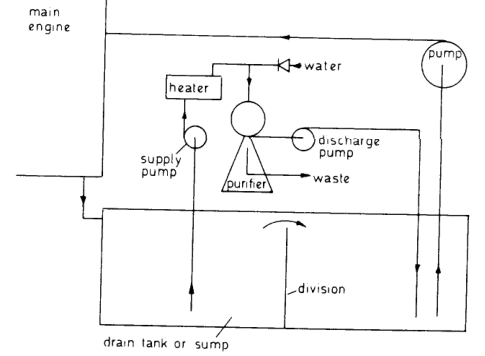
23. Flow tracing exercise
Use the manufacturer’s sectional diagram and trace the phases with three colours:
- Yellow: oil
- Blue: water
- Brown: solids
Start at the feed-liquid inlet and mark:
- Distributor
- Outer disc region
- Disc passages
- Inner oil region
- Interface
- Water region
- Top-disc outside path
- Gravity disc
- Light-liquid impeller
- Heavy-liquid impeller
- Sludge space
- Outlet paths
A correct tracing should produce:
24. Revision questions with answers
Question 1
What are the three phases in purifier operation?
Answer: Oil, water, and solids.
Question 2
Where does feed oil enter the bowl?
Answer: Through the feed-liquid inlet and then into the distributor.
Question 3
What is the distributor’s flow function?
Answer: It accelerates the feed toward bowl speed and directs it to the disc-stack periphery.
Question 4
Which direction does oil move?
Answer: Inward toward the axis and light-liquid outlet.
Question 5
Which direction do water and solids move?
Answer: Outward toward the bowl wall and heavy-liquid region.
Question 6
What happens to solids after they reach the bowl wall?
Answer: They accumulate in the sludge space until discharged.
Question 7
What is the function of the interface?
Answer: It is the boundary between oil and water and must remain correctly positioned.
Question 8
Why is sealing water supplied before oil?
Answer: To establish the water seal and prevent oil from leaving through the heavy-liquid outlet.
Question 9
What does the gravity disc control?
Answer: The heavy-liquid outlet radius and the oil-water interface position.
Question 10
What happens in clarifier operation?
Answer: Oil and solids are separated; normal water-seal and heavy-liquid separation are not used.
Question 11
What causes water in clean oil?
Answer: Incorrect interface position, wrong gravity disc, excess water, blocked water outlet, high feed rate, or related flow problems.
Question 12
What causes oil at the water outlet?
Answer: Interface too far outward, wrong gravity disc, poor water seal, incorrect oil condition, or heavy-liquid-path problems.
25. Self-test problem
Situation
A purifier is running normally, but the clean-oil outlet begins to contain water.
Explain the flow failure
A complete answer should state:
- Water has crossed into the light-liquid region.
- The interface may have moved too far inward.
- The gravity disc may be incorrect.
- Excess sealing or replacement water may be present.
- The heavy-liquid outlet may be restricted.
- Feed temperature, specific gravity, and feed rate must be checked.
- The purifier should not be operated blindly until the cause is identified.
Second situation
Oil is appearing at the water outlet.
Your answer should trace:
Then check:
- Interface too far outward
- Gravity-disc selection
- Water seal
- Oil density and temperature
- Feed rate
- Water-outlet condition
26. Flow-summary table
| Phase | Main movement | Main destination | Final outlet or storage |
|---|---|---|---|
| Oil | Inward | Light-liquid chamber | Clean-oil outlet |
| Water | Outward | Heavy-liquid chamber | Water outlet |
| Solids | Outward to wall | Sludge space | Sludge discharge |
| Sealing water | Outward before feed | Outer bowl region | Establishes water seal |
| Operating water | Hydraulic passages | Main cylinder | Opens/closes bowl |