
Purifier Maintenance, Cleaning, and Inspection
How is a high-speed self-cleaning purifier cleaned, inspected, preserved, and returned to service safely?
Key Principles at a Glance 8 points
- A purifier is a high-speed pressure machine, so maintenance is a safety task: it must be isolated, stopped and treated as rotating machinery, not merely cleaned.
- Cleaning is the most frequent job — bowl, disc stack, sludge ports and operating-water passages must all be clear for separation and discharge to work.
- Discs are inspected for deformation, corrosion and clogged holes, and the disc count and elasticity must match the maker's specification.
- O-rings and O-ring grooves, the main cylinder and the pilot valve are the parts that decide whether the bowl seals and discharges.
- Shafts and bearings are checked for wear, clearance and alignment, because bowl speed and balance depend on them.
- Corrosion control and the correct cleaning schedule depend on the oil type being treated.
- Long suspension of more than three months requires the bowl to be stored separately, the electrical parts preserved, and periodic attention before return to service.
- Assembly quality decides the next running period: correct disc order, correct O-rings, correct torque and correct balance marks.
1. Learning objectives
Course position: Topic 13 of the purifier learning sequence
Main question: How is a high-speed self-cleaning purifier cleaned, inspected, preserved, and returned to service safely?
After studying this lesson, you should be able to:
- Explain why purifier maintenance is safety-critical.
- Prepare a purifier for cleaning and dismantling.
- Describe bowl cleaning and disc-stack inspection.
- Identify important O-rings, sealing surfaces, water passages, and sludge ports.
- Explain inspection of the main cylinder and pilot valves.
- Explain why disc count and disc elasticity matter.
- Identify corrosion, pitting, cracks, and deformation.
- Distinguish acceptable cleaning from unsafe repair.
- Describe long-term suspension preparation.
- Describe maintenance during suspension and return to service.
- Use symptoms to select likely maintenance actions.
- Answer an examination question on purifier maintenance.
2. Why maintenance is safety-critical
A purifier bowl rotates at very high speed. It contains parts that are:
- Highly stressed by centrifugal force
- Exposed to hot oil, water, and sludge
- Sensitive to corrosion and pitting
- Dependent on accurate assembly
- Sealed by precision O-rings and machined surfaces
- Hydraulically operated during opening and closing
A small defect can produce a large operational consequence.
The purifier should therefore be maintained as a rotating pressure machine, not merely washed as a dirty tank.
3. Maintenance principles
Principle 1 — Safe isolation first
Before dismantling:
- Stop the purifier completely.
- Confirm zero bowl speed.
- Switch off and isolate the starter.
- Isolate oil and water supplies.
- Release trapped pressure safely.
- Prevent accidental starting.
Principle 2 — Clean before judging
Sludge can hide:
- Pitting
- Cracks
- Damaged sealing surfaces
- Blocked water passages
- Distorted discs
- Damaged O-ring grooves
Never approve a part by inspecting it through a layer of sludge.
Principle 3 — Do not repair critical defects casually
The manual prohibits welding cracked, pitted, or corroded critical bowl parts. Such components require approved assessment and replacement.
Principle 4 — Assembly is part of maintenance
Correct maintenance includes:
- Correct disc count
- Correct disc orientation
- Correct tightening
- Correct O-ring placement
- Clean water passages
- Correct valve seating
- Correct bowl balance
4. Maintenance categories
| Category | Purpose | Typical examples |
|---|---|---|
| Routine observation | Detect change early | Sound, vibration, current, leakage |
| Operational cleaning | Keep performance stable | Bowl washing, sludge discharge |
| Planned inspection | Find wear before failure | O-rings, discs, valve surfaces |
| Overhaul | Restore mechanical condition | Bowl, shaft, bearings, seals |
| Corrosion inspection | Protect high-stress parts | Pitting, cracks, liquid penetrant |
| Suspension preservation | Protect an idle machine | Drying, rust prevention, desiccant |
| Return-to-service inspection | Verify readiness | Insulation, valves, oil, water, rotation |
The maintenance interval depends on oil properties, sludge load, operating hours, and the maker’s schedule.
5. Maintenance planning
A useful maintenance record includes:
- Date and running hours
- Oil treated
- Feed temperature
- Feed rate
- Discharge interval
- Bowl-cleaning date
- Disc count
- O-ring replacement date
- Bearing condition
- Vibration readings
- Current reading
- Water pressure
- Faults and corrective actions
A trend is often more useful than one isolated reading.
The maker’s inspection schedule must override a convenient but unsuitable calendar interval.
6. Preparation before dismantling
6.1 Confirm the machine is safe
- Complete normal or emergency shutdown.
- Confirm bowl stop from the safety joint, motor fan, or approved zero-speed indicator.
- Turn off the starter.
- Lock or tag the power supply according to ship procedure.
- Close dirty-oil and clean-oil valves.
- Close operating-water valves.
- Drain or depressurise relevant piping.
- Allow hot parts to cool.
6.2 Prepare the workplace
Have available:
- Clean trays for small parts
- Lint-free cloths
- Approved cleaning liquid
- Soft brushes
- O-ring lubricant approved by the maker
- Inspection lamp
- Magnifier
- Torque tools
- Vernier or specified gauges
- New seals and consumables
- Marking system for orientation
- Maker’s assembly drawing
6.3 Prevent contamination
Do not place:
- Discs directly on a dirty deck
- Seals on metal chips
- Precision parts in an unmarked pile
- Wet parts into a closed housing
Cleanliness protects both separation quality and bearing life.
7. Understanding the maintenance area
The main purifier body includes:
- Bowl body
- Bowl hood
- Bowl nut
- Distributor
- Disc stack
- Top disc
- Gravity disc
- Main cylinder or sliding bowl bottom
- Pilot valves
- O-rings and seal rings
- Vertical shaft
- Horizontal shaft and drive
- Gear case
- Gear pump
- Operating-water passages
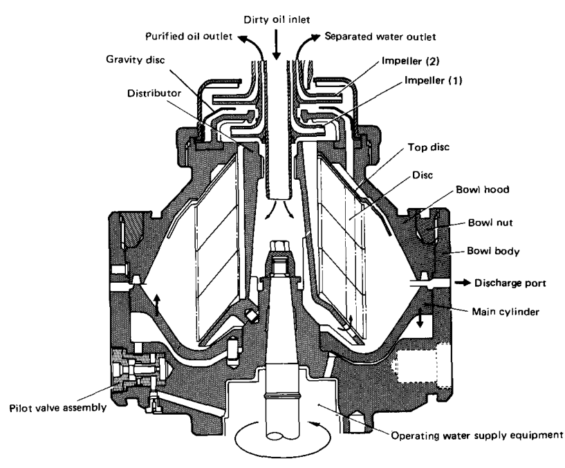
The separation chamber is precision assembled. A cleaning job must preserve the relationship between these parts.
8. Cleaning the bowl
8.1 Remove deposits completely
Clean deposits from:
- Bowl periphery
- Sludge discharge ports
- Disc surfaces
- Distributor passages
- Water chambers
- O-ring grooves
- Pilot-valve areas
- Main-cylinder surfaces
The manual specifically requires thorough cleaning before corrosion inspection.
8.2 Avoid damage during cleaning
Do not:
- Hammer thin discs aggressively
- Scratch sealing surfaces
- Use uncontrolled grinding
- Force a tool into an O-ring groove
- Use a chemical incompatible with seals
- Leave abrasive material in water passages
Use the maker-approved cleaning method.
8.3 Dry after washing
After cleaning:
- Rinse where required.
- Remove all sludge and cleaning residue.
- Blow or wipe water from passages.
- Dry the parts completely.
- Inspect only after the surface is clean and dry.
Moisture left inside the machine promotes corrosion and can affect electrical components.
9. Disc-stack inspection
The disc stack controls the separation distance and effective settling area.
Inspect each disc for:
- Corrosion
- Cracks
- Bent edges
- Torn side portions
- Deformed key grooves
- Missing distance pieces
- Loss of shape
- Deposits that cannot be removed
The manual requires cracked discs to be replaced and does not permit welding repairs to damaged discs.
Why disc condition matters
A damaged disc can:
- Change the separation gap
- Disturb flow between discs
- Create local turbulence
- Reduce separation efficiency
- Produce imbalance
- Damage adjacent discs
10. Disc elasticity and disc count
During service, the disc stack may lose its original compactness.
If the stack elasticity becomes insufficient:
- A gap can form between the top disc and adjacent disc.
- Separation efficiency decreases.
- The stack can become unbalanced.
- A new disc or compensating disc may be required.
The manual states that normally one or more new discs may be added to fill the developed gap, but the correct number must be determined from the maker’s specification and disc figure.
Never add discs by guesswork. Excessive or insufficient stack height can both create faults.
11. Disc assembly precautions
During reassembly:
- Keep all discs in their correct order.
- Align key grooves correctly.
- Ensure discs sit fully on the distributor.
- Confirm distance pieces are present.
- Do not force a disc over a misaligned key.
- Confirm the specified disc count.
- Tighten the bowl nut to the maker’s requirement.
- Confirm the stack is compact and even.
The manual notes that key-groove deformation can occur when discs are not pressed properly during assembly.
12. Bowl-body inspection
Inspect the bowl body after complete cleaning.
12.1 Corrosion and pitting
Corrosion tends to occur where sludge adheres and accumulates.
Look for:
- Pinholes
- Isolated pits
- Linear marks
- Cracks originating from pits
- Roughened surfaces
- Areas with unusual discoloration
The bowl is a highly stressed component. Stainless steel does not mean corrosion is impossible.
12.2 Inspection method
The manual specifies:
- Thorough cleaning
- Visual inspection
- Liquid penetrant examination where required
12.3 Repair limits
Minor approved pitting may be treated only within the maker’s limit. The cited manual specifies that grinder removal must be less than 0.5% and that fine buffing is required afterward.
Do not generalise this limit to another purifier model.
12.4 Cracks and excessive grinding
If a linear defect or crack is present:
- Do not weld it.
- Do not return it to service by informal repair.
- Contact the maker or approved service agent.
- Replace the part or carry out approved balance work.
13. Sludge-discharge ports
Sludge ports must be clear.
Blocked ports can cause:
- Incomplete discharge
- Residual sludge
- Increasing imbalance
- Reduced bowl capacity
- Abnormal vibration
- Poor automatic discharge
Clean each port carefully and confirm that no hardened deposit remains in the passage.
A discharge port is not clean merely because its visible mouth is open. The complete passage must be clear.
14. O-rings and O-ring grooves
O-rings seal:
- Bowl hydraulic chambers
- Water passages
- Main-cylinder sections
- Pilot-valve sections
- Cover and body joints
Inspect O-rings for
- Flattening
- Cuts
- Hardening
- Cracks
- Swelling
- Permanent deformation
- Embedded particles
Replace damaged or doubtful seals according to the maker’s parts list.
Inspect grooves for
- Sludge
- Scale
- Rust
- Burrs
- Scratches
- Roughness
- Deformation
The manual requires every O-ring groove to be cleaned. Rough grooves may be treated with fine sandpaper within the specified limits.
O-ring installation
- Use the correct size and material.
- Clean the groove.
- Lubricate as specified.
- Do not twist the ring.
- Do not stretch it excessively.
- Keep it away from sharp edges.
- Confirm it remains seated during assembly.
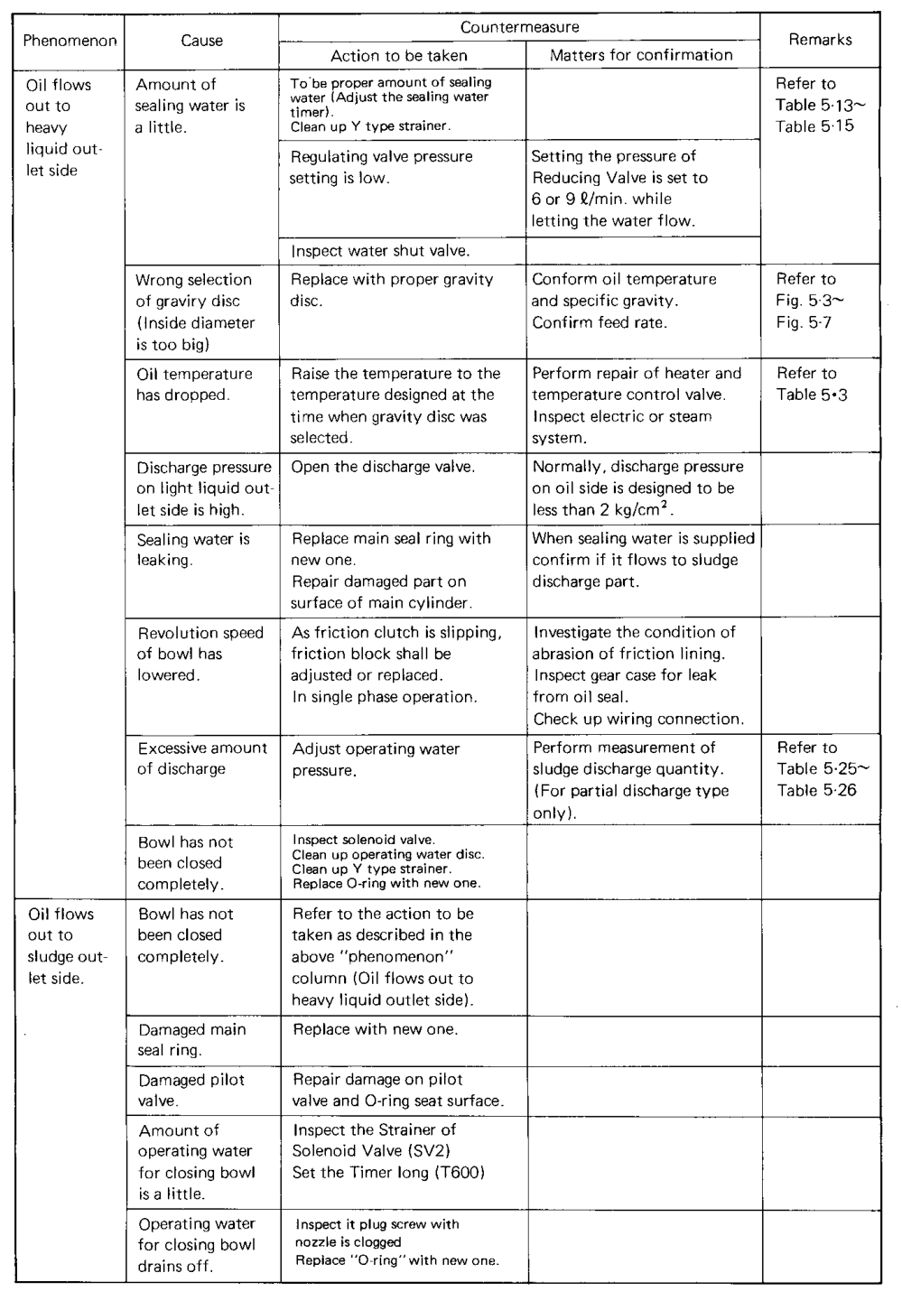
15. Operating-water passages
Hydraulic passages are essential to self-cleaning operation.
Inspect and clean:
- Opening-water passage
- Closing-water passage
- Sealing-water passage
- Replacement-water passage
- Pilot-valve passages
- Main-cylinder chambers
- Strainers and small orifices
Scale or sludge can restrict flow.
The manual specifically requires cleaning clogged operating-water holes and the opening and closing water chambers.
Symptoms of blocked passages
- Bowl cannot open
- Incomplete discharge
- Bowl closes early
- Water detector alarm
- Irregular discharge sound
- Oil leaking to sludge outlet
- Seal not maintained
16. Main-cylinder inspection
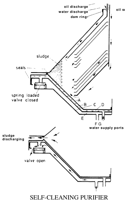
The main cylinder moves the sliding bowl bottom hydraulically.
Inspect:
- Sealing surface against the main seal ring
- Sliding surface
- Chrome-plated area
- Scratches and dents
- Wear marks
- Corrosion
- O-ring contact area
The manual warns that flaws on the sealing surface can damage the main seal ring, cause sealing-water leakage, and disturb normal operation.
Handling rule
Take special care during dismantling. A sealing surface can be damaged by placing the component on a dirty or sharp surface.
Minor approved flaws may be treated with an oilstone. Major damage requires maker-approved repair or replacement.
17. Pilot-valve inspection
Pilot valves control hydraulic switching during bowl operation.
Inspect:
- Sliding surface
- Valve seat
- Sealing surface
- Foreign matter
- Deformation
- Scratches
- O-ring condition
- Free movement
A damaged valve seat can leak operating water and make normal operation impossible.
The manual instructs the operator to clean the valve-seat surface and replace a deformed seat beyond the specified limit.
Pilot-valve fault pattern
18. Vertical shaft and bearing maintenance
The vertical shaft drives the bowl through a high-speed connection.
Inspect for:
- Scoring
- Wear at contact surfaces
- Fretting
- Corrosion
- Runout or deformation
- Bearing noise
- Lubricant contamination
- Damaged springs or supports
Bearings must be the specified type. Substituting an unapproved bearing can change clearance, load capacity, or high-speed reliability.
Symptoms of shaft or bearing problems
- Rising vibration
- Abnormal sound
- Current increase
- Slow acceleration
- Failure to reach rated speed
- Oil leakage at shaft seal
- Excessive heat
Do not continue operation to “see whether it settles” when a bearing or shaft fault is suspected.
19. Horizontal shaft, gear case, and gear pump
Inspect:
- Gear teeth
- Shaft seals
- Couplings
- Safety joint
- Gear-case oil condition
- Pump gears
- Pump connecting tube
- Oil or water contamination
The gear pump must be clean and lubricated as specified.
During long suspension preparation, accumulated oil in the connecting tube must be removed so that it does not flow into the gear pump during reassembly.
Water in the gear case indicates a sealing or drainage problem and must be investigated before operation.
20. Corrosion control
Sources of corrosion
- Wet sludge left in the bowl
- Incomplete drying after washing
- Salt-contaminated water
- Condensation during suspension
- Blocked drains
- Damaged protective surfaces
- Long periods without turning or inspection
Prevention
- Maintain appropriate sludge-discharge intervals.
- Clean during scheduled overhauls.
- Dry all parts completely.
- Apply approved rust-preventive oil.
- Maintain desiccant in electrical enclosures.
- Keep sludge outlets closed during suspension.
- Inspect high-stress bowl areas carefully.
Corrosion prevention is a performance and safety function, not cosmetic housekeeping.
21. Cleaning schedule and oil type
Cleaning interval depends on the treated liquid.
Fuel-oil purifier
May experience:
- Catalyst fines
- Abrasive particles
- High sludge load
- Rapid bowl deposit
It may need frequent discharge and cleaning.
Lubricating-oil purifier
May experience:
- Carbonaceous sludge
- Oxidation products
- Dense sediment after long engine stoppage
- Need for periodic bowl washing
The purifier manual gives different washing and discharge requirements for fuel and lubricating oil. Always use the relevant table.
22. Cleaning during operation: lubricating-oil bowl washing
For lubricating-oil treatment, washing water is introduced at specified intervals before sludge discharge.
The cited operation manual warns that failure to clean the bowl can reduce performance or cause mechanical trouble.
Typical logic:
Do not use fuel-oil washing settings for lubricating-oil operation.
23. Troubleshooting maintenance symptoms
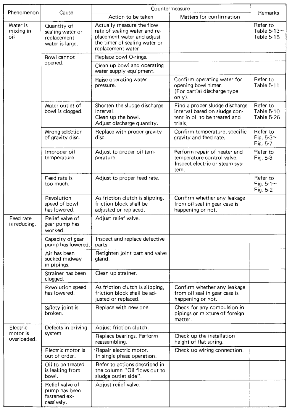
Symptom: bowl does not open
Check:
- Operating-water pressure
- Opening-water valve
- Strainer
- Opening timer
- Water passages
- Main-cylinder seal
- Sludge blockage
The manual lists blocked bowl passages, insufficient pressure, and operating-water equipment as possible causes.
Symptom: incomplete de-sludging
Check:
- Discharge interval
- Discharge quantity
- Sludge port blockage
- Disc-stack condition
- Bowl opening time
- Solenoid valve
- Operating-water pressure
Symptom: water in oil
Check:
- Excess sealing water
- Replacement-water timing
- Damaged O-ring
- Main-cylinder seal
- Bowl closure
- Gravity-disc selection
Symptom: oil to sludge outlet
Check:
- Bowl closure
- Main seal ring
- Operating-water leakage
- Excessive discharge
- Low bowl speed
- Damaged sealing surface
Symptom: vibration after cleaning
Check:
- Disc count
- Disc orientation
- Missing distance pieces
- Bowl nut tightening
- Residual sludge
- Bowl damage
- Shaft and bearing condition
- Correct assembly
24. Maintenance decision tree
The decision tree supports investigation; it does not replace the maker’s maintenance manual.
25. Long-term suspension: more than three months
If the purifier will not be used for more than three months, special preservation is required.
The Mitsubishi suspension procedure includes:
- Disassemble and clean frame and sludge cover.
- Remove moisture completely.
- Apply rust-preventive oil to inside surfaces.
- Clean and lubricate the bowl.
- Apply rust-preventive oil to the outside bowl surface.
- Store the bowl separately rather than reassembling it on the vertical shaft.
- Clean, protect, and reassemble vertical and horizontal shafts.
- Clean the gear case and apply rust-preventive oil.
- Do not refill gear-case lubricating oil until starting.
- Clean and lubricate the gear pump.
- Drain operating-water piping.
- Place desiccant in the Multi-Monitor and electrical equipment.
- Seal electrical equipment against moisture.
- Close the sludge-outlet butterfly valve.
26. Why the bowl is stored separately during suspension
The suspension procedure stores the protected bowl separately from the vertical shaft.
This helps:
- Reduce shaft loading during long inactivity.
- Permit inspection of protected surfaces.
- Prevent moisture from remaining trapped in assembly joints.
- Make preservation status visible.
The procedure must be followed exactly because the bowl and shaft are precision rotating components.
27. Electrical preservation during suspension
Moisture can cause internal rust and insulation deterioration.
During long suspension:
- Place suitable desiccant in the starter.
- Place desiccant in the control panel.
- Place desiccant in the Multi-Monitor.
- Wrap or seal equipment against moisture.
- Replace desiccant at the prescribed interval.
- Carry out insulation checks before re-energising.
Do not energise a damp panel merely to test whether it still works.
28. Maintenance during suspension
For an idle purifier:
- Turn the vertical shaft by hand for two or three minutes at least weekly.
- Carry out quarterly bearing-centred inspections.
- Perform six-month periodic inspections.
- Renew rust-prevention measures.
- Replace desiccant.
- Keep the electrical equipment sealed.
These requirements are stated in the Mitsubishi suspension section.
Turning the shaft helps prevent one-position bearing deterioration and reveals stiffness or abnormal resistance.
29. Returning to service
Before resuming operation after suspension:
Mechanical checks
- Remove preservation oil where required.
- Confirm bowl and shaft assembly.
- Confirm disc count and stack.
- Check all O-rings.
- Check bowl nut and fasteners.
- Confirm no tools or cloths remain inside.
- Confirm sludge outlet is clear.
- Confirm valves move freely.
Hydraulic checks
- Reconnect operating-water piping.
- Open the source valve.
- Check for leaks.
- Clean strainers.
- Confirm opening and closing water.
- Confirm sealing and replacement water.
Electrical checks
- Remove or renew desiccant as required.
- Perform insulation checks.
- Inspect terminals and coils.
- Confirm panel functions.
- Reset alarms.
Operational checks
- Start without feed.
- Confirm acceleration and current.
- Check sound and vibration.
- Confirm rated speed.
- Establish water seal.
- Introduce feed gradually.
- Confirm outlet quality and pressure.
The manufacturer requires inspections prior to running before resuming operation.
30. Maintenance and assembly quality
A clean part can still be incorrectly assembled.
Final assembly inspection should confirm:
Use inspection signatures or a checklist for critical bowl assembly.
31. Maintenance safety rules
- Never dismantle until zero speed is confirmed.
- Never work under trapped hydraulic pressure.
- Never weld a cracked critical bowl part.
- Never substitute an unknown bearing or seal.
- Never mix discs from different sets without approval.
- Never leave sludge or cleaning liquid in the bowl.
- Never install a twisted O-ring.
- Never use excessive force on thin discs.
- Never restart after a vibration fault without investigation.
- Never close up the machine with water in electrical spaces.
- Never rely on appearance alone for high-stress bowl inspection.
- Never omit the maker’s balance and dimensional checks.
32. Maintenance checklist: bowl overhaul
- [ ] Confirm isolation and zero speed.
- [ ] Remove frame and sludge cover safely.
- [ ] Drain and remove remaining liquid.
- [ ] Clean bowl body.
- [ ] Clean disc stack.
- [ ] Clean sludge ports.
- [ ] Clean operating-water holes.
- [ ] Clean opening and closing chambers.
- [ ] Inspect bowl for pits and cracks.
- [ ] Carry out liquid penetrant examination if required.
- [ ] Inspect discs individually.
- [ ] Replace cracked or badly corroded discs.
- [ ] Confirm disc count and elasticity.
- [ ] Inspect key grooves and distance pieces.
- [ ] Clean every O-ring groove.
- [ ] Replace damaged O-rings.
- [ ] Inspect main-cylinder sealing surface.
- [ ] Inspect pilot valves and seats.
- [ ] Inspect shaft contact surfaces.
- [ ] Inspect bearings and supports.
- [ ] Reassemble to maker’s specification.
- [ ] Confirm bowl cleanliness and balance.
33. Maintenance checklist: before restart
- [ ] Bowl fully assembled.
- [ ] Bowl nut correctly tightened.
- [ ] Disc stack correct.
- [ ] Seals correctly installed.
- [ ] Water passages clear.
- [ ] Strainers clean.
- [ ] Oil and water valves correctly positioned.
- [ ] Gear case filled only as specified.
- [ ] Electrical insulation satisfactory.
- [ ] Emergency stop reset.
- [ ] No tools inside frame.
- [ ] Discharge outlet clear.
- [ ] Shaft turns freely by approved method.
- [ ] No abnormal resistance.
- [ ] Start without feed.
- [ ] Current settles correctly.
- [ ] Vibration and sound normal.
- [ ] Water seal established.
- [ ] Feed introduced gradually.
34. Revision questions with answers
Question 1
Why must cleaning precede inspection?
Answer: Sludge can hide corrosion, cracks, blocked passages, and damaged seals.
Question 2
Why is disc count important?
Answer: The disc stack controls separation geometry and balance.
Question 3
What happens if disc-stack elasticity is insufficient?
Answer: A gap can form, reducing separation efficiency and causing imbalance.
Question 4
Can a cracked bowl part be welded?
Answer: No. Follow the maker’s approved replacement or service procedure.
Question 5
Why are O-ring grooves cleaned carefully?
Answer: Dirt or roughness can cause hydraulic leakage and incorrect bowl operation.
Question 6
What does a blocked operating-water passage cause?
Answer: Poor or failed opening, closing, sealing, or sludge discharge.
Question 7
What is inspected on the main cylinder?
Answer: Sealing surface, sliding surface, plating, scratches, wear, and O-ring contact areas.
Question 8
Why inspect pilot-valve seats?
Answer: Leakage at the seat can prevent hydraulic pressure from controlling the bowl.
Question 9
What maintenance is required during a long suspension?
Answer: Cleaning, drying, rust prevention, water draining, desiccant, shaft turning, and periodic inspection.
Question 10
Why is the bowl stored separately during long suspension?
Answer: To protect the shaft/bowl assembly and prevent trapped moisture and long-term loading.
Question 11
What should be checked before reintroducing feed after overhaul?
Answer: Speed, current, sound, vibration, water seal, leakage, and correct outlet operation.
Question 12
What is the most important maintenance rule?
Answer: Do not dismantle or inspect a high-speed purifier until it is completely stopped and isolated.
35. Self-test scenario
Scenario
After overhaul, the purifier reaches speed but vibrates strongly and the current is higher than normal.
Correct investigation
- Stop feed.
- Stop the purifier safely.
- Confirm zero speed and isolate power.
- Check for residual sludge.
- Check disc count and orientation.
- Check missing distance pieces.
- Check bowl-nut tightening.
- Check bowl and disc damage.
- Check shaft and bearing condition.
- Check that the bowl was assembled according to maker dimensions.
- Do not continue operation hoping vibration will disappear.
Scenario 2
The bowl does not open during a discharge test.
Correct investigation
- Confirm operating-water pressure.
- Inspect water strainer.
- Check opening-water valve and timer.
- Clean operating-water passages.
- Check main-cylinder and O-ring condition.
- Check pilot valve and seat.
- Check for sludge blockage at discharge ports.
- Test again only after the defect is corrected.