
Purifier Oil-Water Interface and Gravity Disc
How is the oil-water boundary positioned, and how is the correct gravity disc selected?
Key Principles at a Glance 8 points
- The oil-water interface is the single control point of a purifier: sit it correctly and oil leaves clean, move it and both outlets become contaminated.
- Interface position is set by the gravity disc — a larger inside diameter holds the interface further out, a smaller one lets it move inward.
- Gravity-disc selection needs the oil's specific gravity at the treating temperature, the treating temperature itself, and the expected feed rate.
- Because temperature changes oil density, a disc chosen for one treating temperature can be wrong at another.
- If the interface moves too far inward, oil escapes with the water; if it moves too far outward, water contaminates the clean oil.
- Sealing water establishes the initial interface, so a poor water seal means the interface starts in the wrong place.
- Outlet back pressure also shifts the interface, so outlet-pressure adjustment and disc selection work together.
- A clarifier has no gravity disc and no water outlet, so it cannot be used where water removal is required.
1. Learning objectives
Course position: Topic 7 of the purifier learning sequence
Main question: How is the oil-water boundary positioned, and how is the correct gravity disc selected?
After studying this lesson, you should be able to:
- Define the oil-water interface inside a purifier bowl.
- Explain why interface position is critical.
- Explain how the gravity disc controls the heavy-liquid outlet.
- State the effect of a larger and smaller gravity-disc inside diameter.
- Select a gravity disc using specific gravity, treating temperature, and feed rate.
- Explain the difference between specific gravity at 15°C and at another temperature.
- Work through the manufacturer’s gravity-disc examples.
- Diagnose oil at the water outlet and water in clean oil.
- Explain how sealing water affects the interface.
- Understand why a new oil grade requires a new operating check.
2. The interface: the central control point
Inside a purifier bowl, oil and water form two liquid regions.
- Oil is the light liquid.
- Water is the heavy liquid.
- The boundary between them is the interface.
The interface must remain within a limited area of the bowl. If it moves too far, the liquid phases reach the wrong outlets.
The Mitsubishi manual defines the interface as the boundary between the light liquid and the heavy liquid within the bowl.
3. Why interface position matters
The purifier has two liquid outlets:
- Light-liquid outlet for clean oil
- Heavy-liquid outlet for separated water
The interface must divide the bowl so that:
- Oil reaches the light-liquid outlet.
- Water reaches the heavy-liquid outlet.
- Solids move to the bowl wall.
An incorrect interface causes carry-over.
Interface too far inward
The heavy-liquid region extends too close to the axis.
Possible result:
- Water enters the light-liquid region.
- Water appears in clean oil.
- Clean-oil quality decreases.
Interface too far outward
The light-liquid region extends too far toward the bowl wall.
Possible result:
- Oil enters the heavy-liquid path.
- Oil appears at the water outlet.
- Oil losses increase.
4. How the interface is created
The interface is established by the balance of:
- Centrifugal forces
- Oil density
- Water density
- Liquid flow rates
- Heavy-liquid outlet radius
- Light-liquid outlet conditions
- Sealing-water condition
- Feed rate
- Temperature and viscosity
The interface is therefore not simply a fixed physical ring. It is a hydraulic boundary created by the operating condition.
The gravity disc changes the heavy-liquid outlet geometry and is the main interface adjustment component in the Selfjector arrangement.
5. The gravity disc
The gravity disc is a replaceable disc used in the heavy-liquid outlet path.
Its important feature is the inside diameter.
The Mitsubishi manual states that different gravity-disc inside diameters are used to adjust the interface.
5.1 Larger inside diameter
A larger gravity-disc inside diameter moves the interface outward.
5.2 Smaller inside diameter
A smaller gravity-disc inside diameter moves the interface inward.
These directions are explicitly stated in the Mitsubishi operation manual.
6. Interface movement diagram
The exact radial direction must always be interpreted together with the manufacturer’s model-specific diagram. The Selfjector manual’s direct rule is:
- Larger inside diameter → interface outward.
- Smaller inside diameter → interface inward.
7. Purifier bowl flow and gravity disc location
The liquid paths are:
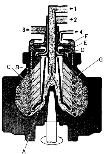
The Mitsubishi manual identifies:
- Feed-liquid inlet
- Light-liquid outlet
- Heavy-liquid outlet
- Sealing-water inlet
- Distributor
- Disc stack
- Top disc
- Light-liquid impeller
- Gravity disc
- Heavy-liquid impeller
- Interface
[Purifier—Mitsubishi Selfjector Manual 1, p. 58]
8. Why the correct disc is important
The gravity disc must match the liquid being treated.
The Mitsubishi manual warns that before treating a different type or nature of oil, a suitable gravity disc must be selected according to the treated oil’s gravity. Running with an incorrect diameter can cause:
- Oil outflow to the heavy-liquid side
- Water circulation over the light-liquid side
[Purifier—Mitsubishi Selfjector Manual 2, p. 24]
Incorrect disc symptoms
| Symptom | Possible interface condition |
|---|---|
| Water in clean oil | Interface too far inward or water-side problem |
| Oil at water outlet | Interface too far outward or oil-side problem |
| Unstable outlet streams | Incorrect disc, feed, temperature, or pressure |
| Frequent water detection | Interface or water-load problem |
| Poor separation after fuel change | Old disc no longer matches oil condition |
Never select a disc only by the oil name. The selection requires actual operating data.
9. Data needed for gravity-disc selection
The main selection inputs are:
- Purifier model
- Oil type
- Specific gravity
- Temperature at which specific gravity is known
- Separating or treating temperature
- Feed rate
- Manufacturer’s selection nomogram or table
The Mitsubishi manual gives nomograms using specific gravity, separating temperature, feed rate, and gravity-disc inside diameter.
10. Specific gravity and temperature
Specific gravity changes with temperature. Therefore the operator must know whether the value is given at:
- 15°C
- 50°C
- Another specified temperature
Examples:
- 0.925 at 15°C
- 0.944 at 50°C
These are not interchangeable values.
If the manual’s nomogram requires a value at 15°C but the available measurement is at 50°C, the value must be converted or followed through the graph’s temperature-conversion procedure.
The Mitsubishi gravity-disc examples distinguish between:
- Case 1: specific gravity at 15°C is known.
- Case 2: specific gravity at another temperature is known.
[Purifier—Mitsubishi Selfjector Manual 1, p. 32]
11. Feed rate and interface position
Feed rate changes the hydraulic condition inside the bowl.
A disc selected for 3000 L/h should not automatically be assumed correct at a substantially different feed rate.
The correct selection procedure uses feed rate as one of the nomogram inputs.
Excessive feed rate can cause
- Reduced residence time
- Poor separation
- Fine water droplets remaining in oil
- Solids passing with clean oil
- Interface instability
- Outlet carry-over
12. Treating temperature and interface position
Temperature affects the interface in two ways:
- It changes viscosity and therefore flow resistance.
- It changes oil density and specific gravity.
If the oil is heated to a different treating temperature from the condition used when selecting the disc, the interface may no longer be in the intended position.
This is why gravity-disc selection and treating-temperature selection must be considered together.
13. Sealing water and the initial interface
Before feed oil is introduced, sealing water is supplied.
The sealing water:
- Occupies the heavy-liquid region.
- Prevents oil from escaping through the water outlet.
- Establishes the initial liquid arrangement.
- Helps the interface form at the correct location.
The Mitsubishi manual states that sealing water passes past the gravity disc and outside the top disc before accumulating at the bowl periphery.
Incorrect sealing-water condition
If sealing water is insufficient:
- Oil may flow to the heavy-liquid side.
- The interface may fail to establish.
- Oil losses may occur during start-up.
If sealing or replacement water is excessive:
- Water may mix with clean oil.
- The heavy-liquid load may increase.
- Interface control may become unstable.
14. Gravity-disc selection procedure: general method
Use this procedure only with the correct manufacturer’s nomogram for the installed model.
Step 1: identify the purifier model
Nomograms differ by model. Confirm the exact model designation.
Step 2: identify the oil
Record:
- Fuel or lubricating oil
- Grade or service
- Whether the oil has changed from the previous batch
Step 3: obtain specific gravity
Record:
- Specific-gravity value
- Reference temperature
- Measurement method
- Sample identity
Step 4: determine treating temperature
Use the viscosity-temperature relationship and the manufacturer’s limit.
Step 5: determine feed rate
Use the actual intended operating flow, not merely the pump’s maximum capability.
Step 6: use the nomogram
Follow the model-specific graph to the gravity-disc inside-diameter scale.
Step 7: install and verify
Install the selected disc and monitor:
- Clean-oil outlet
- Water outlet
- Interface behaviour
- Water carry-over
- Oil carry-over
15. Gravity-disc example 1
The Mitsubishi manual gives this condition:
- Specific gravity: 0.925 at 15°C
- Treating temperature: 70°C
- Feed rate: 3000 L/h
- Selected gravity-disc inside diameter: approximately φ79 mm
Graph procedure
- Locate the curve for specific gravity 0.925.
- Move to the vertical line for 70°C.
- Draw the horizontal construction line to the reference-temperature side.
- Connect the resulting point to 3000 L/h on the capacity scale.
- Read the gravity-disc inside-diameter range.
- Select approximately φ79 mm for the stated example.
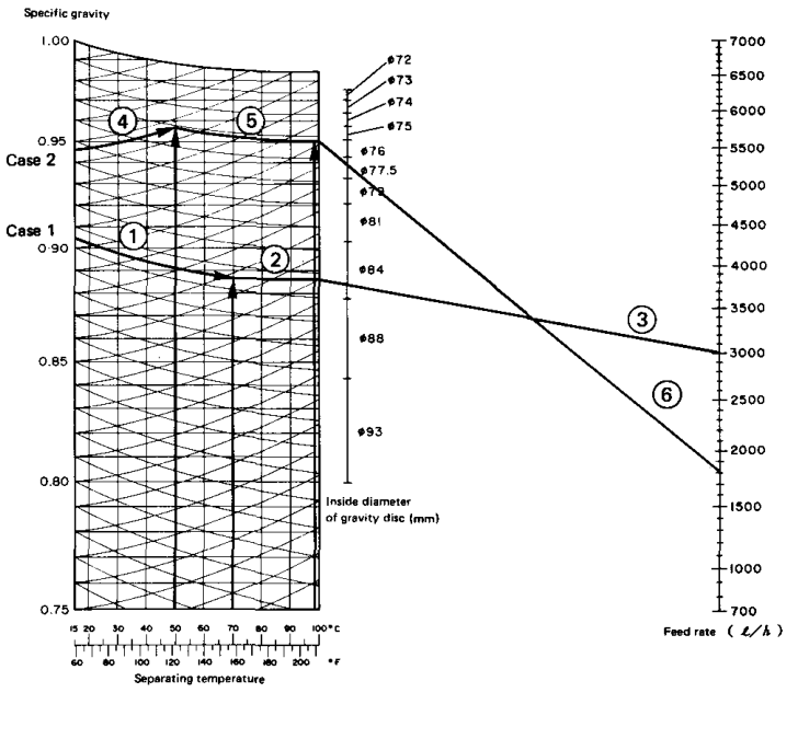
This result applies only to the stated purifier model and operating condition.
16. Gravity-disc example 2
The Mitsubishi manual gives a second condition:
- Specific gravity: 0.944 at 50°C
- Treating temperature: 98°C
- Feed rate: 1250 L/h
- Selected gravity-disc inside diameter: approximately φ71.5 mm
Why this example is different
The specific gravity is not initially given at 15°C. The graph procedure first converts or follows the appropriate temperature curve before connecting the condition to the feed-rate scale.
The procedure is:
- Locate the 0.944 curve at 50°C.
- Follow the conversion path to the treating temperature of 98°C.
- Transfer to the reference-temperature scale.
- Connect the condition to 1250 L/h.
- Read the gravity-disc inside-diameter range.
- Select approximately φ71.5 mm for the stated example.
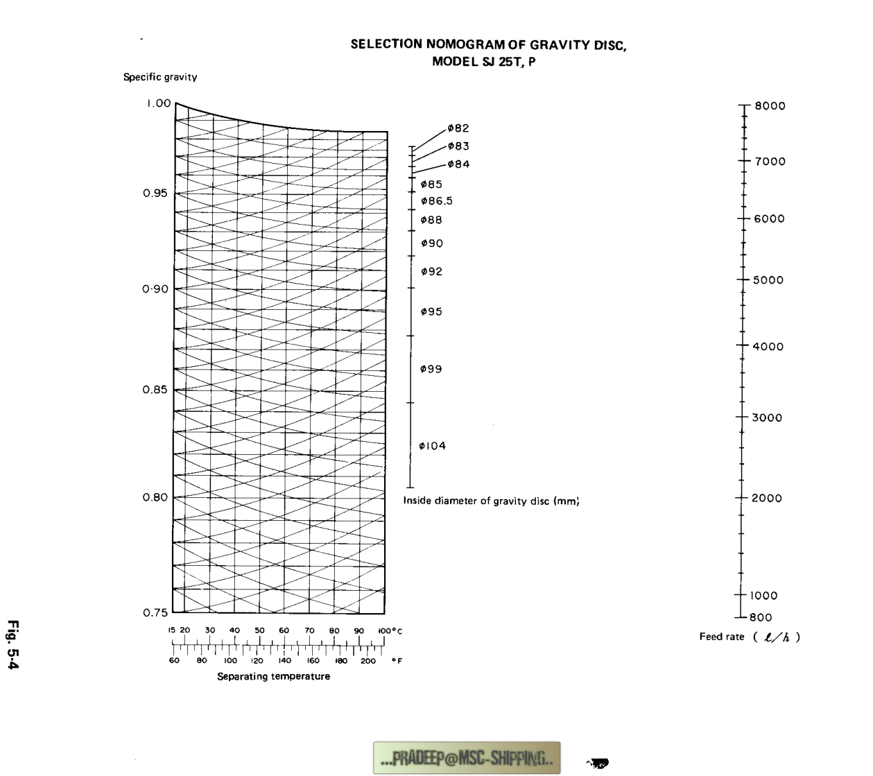
17. Reading model-specific nomograms
The nomogram varies with purifier model.
Examples in the indexed manual include nomograms for:
- SJ25T.P
- SJ30T.P
- SJ40T.P
- SJ60T.P
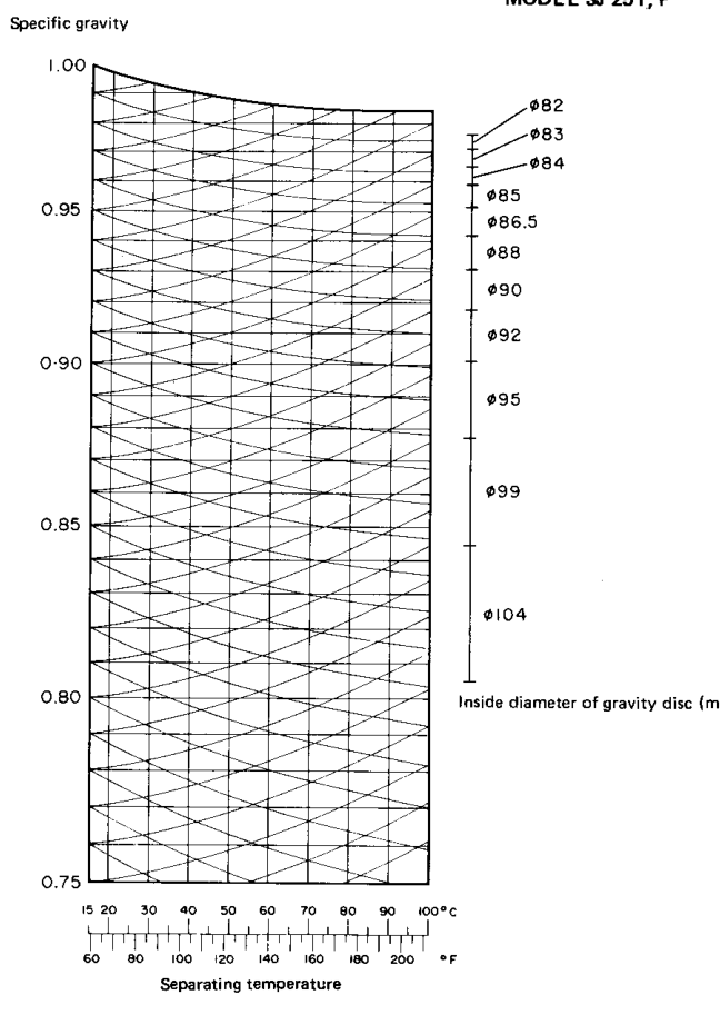
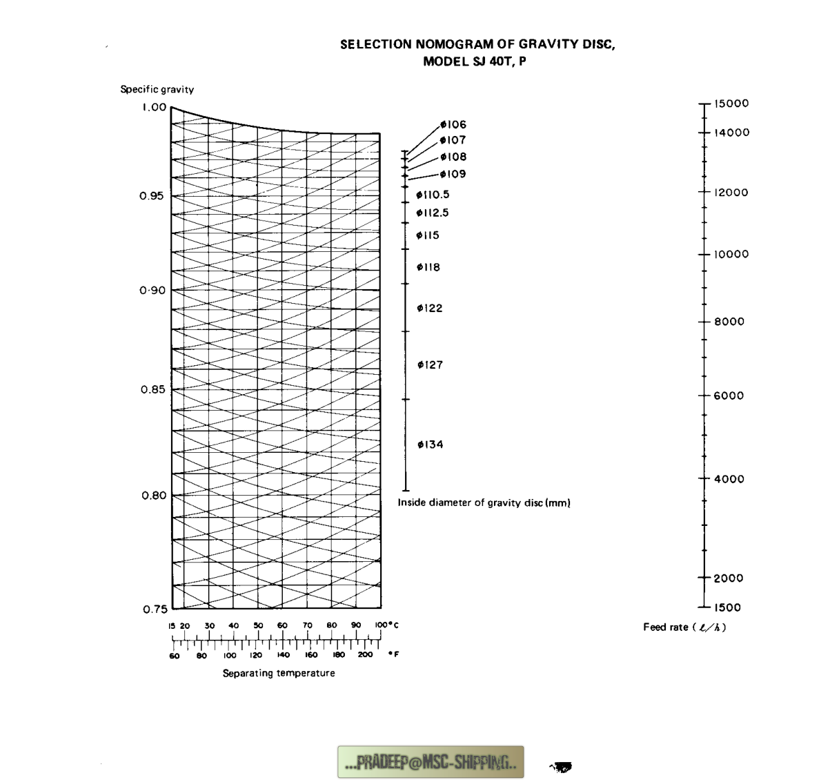
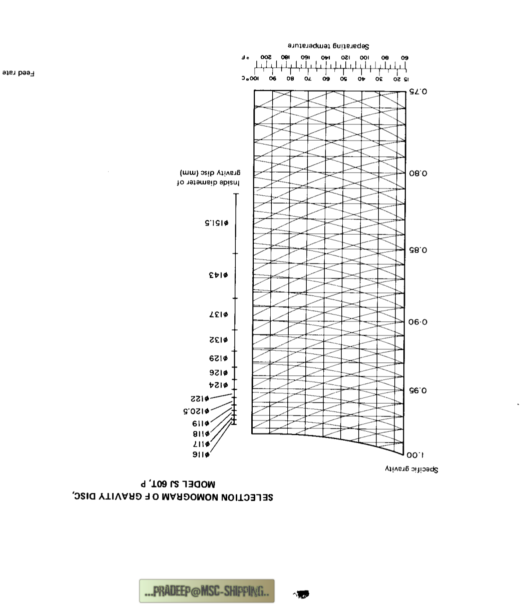
Do not use a nomogram from another model simply because the graph looks similar.
18. What happens when oil changes
Suppose the purifier was treating Fuel A and now receives Fuel B.
Fuel B may have a different:
- Specific gravity
- Viscosity
- Water content
- Treating temperature
- Feed-rate requirement
The interface condition can therefore change.
The Mitsubishi manual specifically warns that a suitable gravity disc must be selected before treating a different type or nature of oil.
19. Fault: water in clean oil
Water in the light-liquid outlet means the water phase has reached or crossed into the clean-oil region.
Investigation sequence
- Confirm actual oil temperature.
- Confirm the oil’s specific gravity.
- Confirm actual feed rate.
- Check the selected gravity disc.
- Check sealing-water and replacement-water flow.
- Check the heavy-liquid outlet for blockage.
- Check whether the bowl contains excessive water load.
- Check the top disc and outlet assembly.
- Check whether the bowl speed is normal.
The manufacturer’s troubleshooting information links water mixing in oil with water quantity, blocked water outlet, incorrect gravity disc, temperature, specific gravity, feed rate, and reduced bowl speed.
Flow explanation
20. Fault: oil at the water outlet
Oil at the heavy-liquid outlet means the oil region has reached too far outward or the water seal/interface condition is incorrect.
Investigation sequence
- Confirm sealing water was supplied correctly.
- Check the gravity-disc inside diameter.
- Confirm oil specific gravity and reference temperature.
- Confirm treating temperature.
- Confirm feed rate.
- Check the heavy-liquid outlet path.
- Check the interface condition.
- Check for incorrect bowl assembly.
Flow explanation
21. Gravity-disc installation
The gravity disc is fitted in the heavy-liquid side of the bowl.
During installation:
- Confirm the correct disc diameter.
- Confirm the correct purifier mode.
- Clean the disc and seating surfaces.
- Inspect for damage.
- Fit the disc in the correct orientation.
- Install associated packing and chambers correctly.
- Confirm the heavy-liquid impeller is correctly fitted.
The dismantling instructions identify the heavy-liquid chamber, heavy-liquid impeller, packing, and gravity disc as a related assembly.
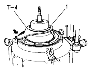
Never change the gravity disc while the purifier is rotating.
22. Purifier versus clarifier gravity-disc arrangements
In purifier operation, the gravity disc controls the heavy-liquid side and the oil-water interface.
In clarifier operation, the machine uses a clarifier arrangement rather than a normal oil-water interface arrangement.
The Mitsubishi manual notes that some purifier models are supplied with clarifier gravity-disc parts or arrangements for clarifying operation.
Therefore:
- A purifier gravity disc is not automatically a clarifier part.
- A clarifier arrangement is not automatically suitable for three-phase purification.
- The operating mode and installed parts must match.
23. Interface and outlet pressure
The interface is affected not only by the gravity disc but also by the outlet hydraulic condition.
Changes in:
- Light-liquid back pressure
- Heavy-liquid discharge resistance
- Outlet-valve position
- Pump condition
- Piping restriction
can change the liquid balance.
A purifier that was stable yesterday may become unstable after:
- A valve is partially closed.
- A discharge line becomes restricted.
- A pump relief setting changes.
- A water outlet becomes blocked.
- The feed rate changes.
The correct response is to check the entire flow system, not only replace the gravity disc.
24. Practical interface-monitoring table
| Observation | Likely meaning | First checks |
|---|---|---|
| Clean oil dry and water outlet clear | Interface likely satisfactory | Continue normal monitoring |
| Water in clean oil | Interface too inward or water-side overload | Disc, water flow, outlet, temperature, feed |
| Oil in water outlet | Interface too outward or poor water seal | Disc, sealing water, density, feed |
| Both outlets unstable | Hydraulic or operating imbalance | Speed, pressure, flow, bowl assembly |
| Carry-over after fuel change | Disc no longer matches liquid | New specific gravity, temperature, feed rate |
| Carry-over after heater fault | Density and viscosity changed | Heater, temperature control, disc condition |
25. A complete worked decision example
Condition
A purifier was treating fuel with:
- Specific gravity 0.925 at 15°C
- Treating temperature 70°C
- Feed rate 3000 L/h
- Gravity disc approximately φ79 mm
A new fuel arrives with a different density and is treated at a different temperature.
Correct action
- Do not continue assuming φ79 mm is correct.
- Obtain the new fuel’s specific gravity and reference temperature.
- Determine its treating temperature.
- Confirm the intended feed rate.
- Select the correct model-specific nomogram.
- Select the new gravity-disc diameter.
- Install the disc safely.
- Establish the water seal.
- Start feed gradually.
- Check both outlets.
Incorrect action
- Increase feed rate to force more capacity.
- Change the disc by guesswork.
- Ignore oil at the water outlet.
- Continue despite water in clean oil.
- Use a disc from another purifier model.
26. Common misunderstandings
Misunderstanding 1: “The gravity disc filters water.”
Incorrect. It controls the heavy-liquid outlet radius and interface position.
Misunderstanding 2: “A larger gravity disc always gives better purification.”
Incorrect. The correct size depends on the liquid condition and purifier model.
Misunderstanding 3: “The gravity disc depends only on specific gravity.”
Incorrect. Temperature and feed rate are also part of the selection condition.
Misunderstanding 4: “A disc selected once can be used forever.”
Incorrect. New oil, new temperature, or new feed rate may require re-selection.
Misunderstanding 5: “Water in clean oil always means a dirty disc stack.”
Incorrect. Interface, water flow, outlet restriction, temperature, density, and feed rate must also be checked.
Misunderstanding 6: “Oil at the water outlet is harmless.”
Incorrect. It indicates oil loss and an incorrect phase boundary or seal condition.
Misunderstanding 7: “Specific gravity at any temperature can be entered directly.”
Incorrect. Use the temperature-conversion procedure required by the manufacturer’s nomogram.
27. Revision questions with answers
Question 1
What is the interface?
Answer: The boundary between the light liquid, normally oil, and the heavy liquid, normally water.
Question 2
What does the gravity disc control?
Answer: The heavy-liquid outlet diameter and the oil-water interface position.
Question 3
What happens when a larger inside-diameter gravity disc is fitted?
Answer: The interface moves outward.
Question 4
What happens when a smaller inside-diameter gravity disc is fitted?
Answer: The interface moves inward.
Question 5
What happens if the interface moves too far inward?
Answer: Water may enter the light-liquid outlet and mix with clean oil.
Question 6
What happens if the interface moves too far outward?
Answer: Oil may enter the heavy-liquid outlet and be lost with the water.
Question 7
What data are needed for gravity-disc selection?
Answer: Purifier model, specific gravity, reference temperature, treating temperature, and feed rate.
Question 8
Why is sealing water supplied before oil feed?
Answer: To establish the heavy-liquid region and prevent oil from flowing to the water outlet.
Question 9
Why must specific gravity’s reference temperature be known?
Answer: Specific gravity changes with temperature.
Question 10
Why does feed rate affect disc selection?
Answer: It changes the hydraulic condition, residence time, and interface balance.
Question 11
What should be done when treating a different oil?
Answer: Check its specific gravity, temperature, feed rate, and select the appropriate gravity disc.
Question 12
What are the first checks when water mixes with clean oil?
Answer: Water flow, water outlet, temperature, specific gravity, feed rate, bowl speed, and gravity disc.
28. Self-test calculation and diagram exercise
Use this stated manufacturer example:
- Specific gravity: 0.925 at 15°C
- Treating temperature: 70°C
- Feed rate: 3000 L/h
- Gravity-disc selection: approximately φ79 mm
Answer:
- Why cannot the disc be selected from specific gravity alone?
- Why must the purifier model be identified first?
- Why does 70°C appear in the selection procedure?
- Why does 3000 L/h appear in the selection procedure?
- What could happen if the same disc is used at a much higher feed rate?
- What could happen if the fuel is changed to a higher-density grade?
Then draw:
- The axis of rotation
- Oil region
- Water region
- Interface
- Gravity disc
- Light-liquid outlet
- Heavy-liquid outlet
Mark the interface movement for:
- Larger gravity-disc inside diameter
- Smaller gravity-disc inside diameter
29. Operating checklist for interface control
Before treating a new oil:
- [ ] Confirm purifier model.
- [ ] Confirm purifier is in purifier mode, not clarifier mode.
- [ ] Obtain specific gravity and reference temperature.
- [ ] Obtain viscosity and measurement temperature.
- [ ] Determine treating temperature.
- [ ] Determine intended feed rate.
- [ ] Select the correct gravity-disc nomogram.
- [ ] Fit the correct gravity disc.
- [ ] Inspect disc, packing, and heavy-liquid chamber.
- [ ] Establish sealing water before oil feed.
- [ ] Start feed gradually.
- [ ] Observe clean-oil and water outlets.
- [ ] Record the final operating condition.