
Purifier Start-Up Sequence
How is a purifier safely started, sealed, heated, and brought into oil feed?
Key Principles at a Glance 7 points
- Start-up is a staged sequence, not a single switch: inspect, spin the bowl to rated speed, heat the oil, close the bowl, establish the water seal, then admit feed gradually.
- Oil must never be fed before the bowl is closed and the water seal established, otherwise the interface is lost and oil escapes to the water or sludge outlet.
- The bowl must reach rated speed before sealing water or feed is introduced, because at low speed the seal cannot form and the bowl cannot separate.
- Oil is heated towards the recommended treating temperature before or during feed admission, since ambient viscosity is too high for effective separation.
- Feed rate is raised gradually and outlet pressure adjusted once feed is stable, so the interface has time to settle.
- Normal start-up is confirmed by stable current, low vibration, correct outlet pressures and clean oil — not by the machine merely running.
- Any abnormal vibration, sound or current during start-up is a stop-now condition, not something to watch.
1. Learning objectives
Course position: Topic 9 of the purifier learning sequence
Main question: How is a purifier safely started, sealed, heated, and brought into oil feed?
After studying this lesson, you should be able to:
- Explain why pre-start inspections are required.
- Prepare the purifier for start-up.
- Start the bowl safely and recognise normal start-up behaviour.
- Explain why the bowl must reach rated speed before oil feed.
- Start and control the heater.
- Establish sealing water and close the bowl.
- Start automatic running in the correct sequence.
- Introduce feed oil gradually.
- Adjust feed rate and outlet pressure.
- Identify abnormal sound, vibration, current, and speed.
- State when start-up must be stopped immediately.
- Trace the complete start-up sequence from inspection to stable purification.
2. Why start-up sequence matters
A purifier is a high-speed rotating machine containing oil, water, hydraulic pressure, and a precision-balanced bowl.
The start-up sequence must establish four conditions in the correct order:
- Mechanical readiness — the bowl can rotate safely.
- Thermal readiness — the oil has the correct viscosity and temperature.
- Hydraulic readiness — the bowl is closed and the water seal is established.
- Flow readiness — oil enters at the correct feed rate and reaches the correct outlets.
Starting in the wrong order can cause:
- Oil flowing to the water outlet
- Water entering clean oil
- Bowl overflow
- Poor separation
- Mechanical damage
- Excessive vibration
- Unsafe operation
Reed’s gives the basic purifier order as: operating speed, fresh water for the water seal, and then oil feed.
3. Manufacturer’s start-up principle
The Mitsubishi manual requires pre-running inspections before start-up and gives specific warnings about abnormal sound and vibration.
The practical principle is:
Do not feed oil into a purifier that has not reached speed, temperature, and hydraulic readiness.
The exact valve positions, control-panel sequence, heater setting, water quantity, and pressure values depend on the installed purifier model. The maker’s manual and shipboard operating procedure always take priority over this learning chapter.
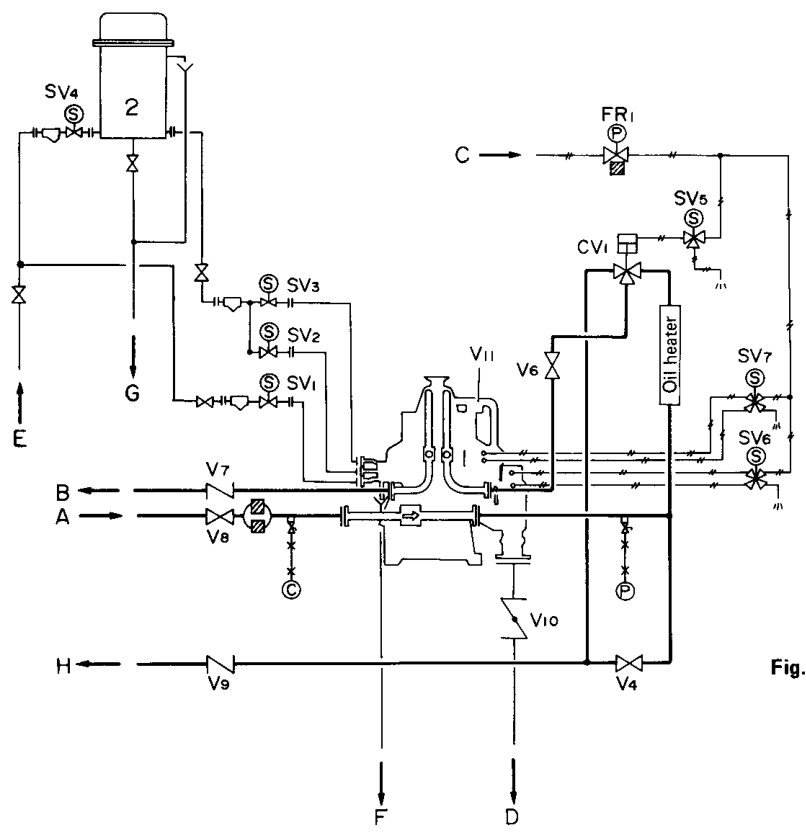
4. Start-up overview diagram
5. Stage 1 — Pre-start inspection
The purifier must be inspected before electrical start-up.
5.1 Mechanical checks
Confirm:
- Bowl is correctly assembled.
- Bowl nut is correctly secured.
- Frame cover is installed and locked.
- Disc stack is correctly fitted.
- Gravity disc matches the oil condition.
- No tools or foreign objects remain inside.
- Spindle and drive are ready.
- Oil level and lubrication condition are correct.
- Foundation and fasteners are secure.
- Connected pipes are supported.
5.2 Valve and line checks
Confirm the correct positions for:
- Dirty-oil inlet valve
- Clean-oil outlet valve
- Bypass valve
- Flow-control valve
- Circulation valve
- Butterfly valve
- Water shut valve
- Feed valve
- Sludge and separated-water outlet
- Operating-water drain
The Mitsubishi system diagram identifies valves including the bypass valve, flow-control valve, purified-oil outlet valve, dirty-oil inlet valve, circulation valve, butterfly valve, water shut valve, and feed valve.
5.3 Water-system checks
Confirm:
- Operating-water tank contains water.
- Sealing-water supply is available.
- Replacement-water supply is available where applicable.
- Operating-water pressure is correct.
- Water strainers are clear.
- Solenoid valves can operate.
- Water drain lines are open and safe.
5.4 Oil-system checks
Confirm:
- Correct oil source is selected.
- Settling or supply tank has sufficient oil.
- Oil is compatible with the selected purifier mode.
- Heater is ready.
- Feed pump is available.
- Oil temperature instruments work.
- Bypass and circulation routes are available.
5.5 Control and safety checks
Confirm:
- Starter is ready.
- Automatic control panel is powered as required.
- Alarms are healthy.
- Emergency stop is available.
- Leakage monitor is ready where fitted.
- Interlocks are not bypassed.
- Discharge timer is set correctly.
6. Stage 2 — Start the bowl
Press the starter START control according to the maker’s procedure.
6.1 What happens during acceleration
The bowl passes through increasing speeds before reaching rated speed.
During this period:
- The motor current is high initially.
- The bowl accelerates.
- Temporary vibration may occur while passing a critical speed.
- Current should reduce as the bowl approaches normal speed.
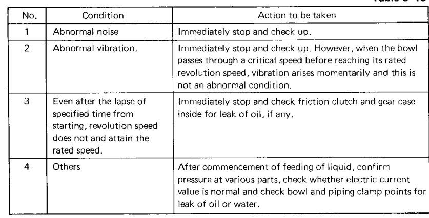
The Mitsubishi manual states that temporary vibration may occur just after start-up while the bowl passes through a critical speed, but large vibration at rated speed is abnormal.
6.2 Monitor immediately
Watch and listen for:
- Abnormal sound
- Contact or rubbing sound
- Excessive vibration
- Motor current
- Oil leakage
- Water leakage
- Failure to accelerate
- Unusual smell or heating
If abnormal sound is heard, stop immediately and investigate.
7. Stage 3 — Confirm rated speed
The purifier must reach its rated number of revolutions before normal oil feed.
The Mitsubishi operation instructions state that rated speed is usually achieved approximately 5–10 minutes after start-up, depending on the machine.
Do not use time alone as proof of speed. Confirm the available speed or operating indication.
7.1 Current indication
The manual gives a typical start-up check that current settles to approximately 50–70% of rated current after start-up, subject to the installed model and manual table.
This is an indication, not a universal acceptance value.
7.2 Why rated speed is required
At rated speed:
- Centrifugal force is sufficient.
- The bowl hydraulic balance can form correctly.
- The water seal can be established.
- The disc stack operates at its intended condition.
- The outlet impellers generate their designed pressure.
8. Stage 4 — Start oil circulation and heating
After the bowl reaches normal speed, oil circulation and heating are established.
8.1 Start the heater
Start the oil heater according to the shipboard procedure.
Confirm:
- Feed oil is circulating through the heater.
- Heater outlet temperature rises.
- Temperature control responds.
- No heater alarm occurs.
- Oil is not being overheated.
The Mitsubishi manual instructs the operator to make sure the feed liquid is circulating in the heater and heated to the specified temperature.
8.2 Not every oil requires the same heating
Some lower-viscosity oils may not require preheating. The manual gives diesel or A heavy oil as examples where heating may not be required under suitable conditions.
Never assume “heater off” is correct without checking:
- Oil viscosity
- Oil type
- Purifier model
- Required treatment temperature
- Manufacturer’s graph
8.3 Temperature target
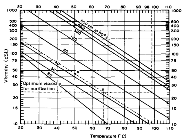
Use the manufacturer’s temperature-viscosity graph.
The referenced Mitsubishi manual uses approximately 24 cSt as an optimum viscosity condition for its example and limits the maximum heating temperature to below approximately 100°C.
9. Stage 5 — Close the bowl
Before normal oil feed, the bowl must be closed hydraulically.
The closing-water system moves the sliding bowl bottom or main cylinder into the sealed position.
Closing sequence
Confirm:
- Closing-water supply is available.
- Bowl closes fully.
- No abnormal water leakage occurs.
- The control panel indicates the correct state.
- Sludge-discharge openings are not left open.
A bowl that is not fully closed can leak oil, water, or sludge and must not be fed normally.
10. Stage 6 — Establish the water seal
Sealing water is supplied after the bowl is at speed and in the correct closed condition.
Purpose of the water seal
- Establish the heavy-liquid region.
- Prevent oil from escaping through the heavy-liquid outlet.
- Prepare the oil-water interface.
- Stabilise the purifier before feed.
Water-seal sequence
The general purifier sequence in Reed’s is operating speed, fresh water for the seal, and then oil feed.
Water-seal checks
Confirm:
- Water reaches the correct inlet.
- Water flow is not excessive.
- No water leaks from unintended locations.
- The water outlet or discharge path responds normally.
- The correct gravity disc is installed.
11. Stage 7 — Automatic start sequence
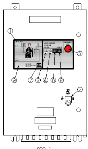
The automatic control panel runs the programmed water and feed sequence.
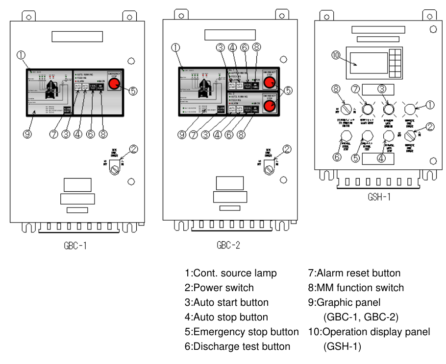
The Mitsubishi manual describes the AUTO START control as beginning the predetermined automatic running sequence after the purifier reaches rated speed.
One stated automatic sequence is:
The exact sequence varies by purifier type and control configuration.
What to observe during automatic start
- Discharge sound or current change
- Water-valve operation
- Bowl closing
- Sealing-water supply
- Feed-valve movement
- Oil entering the purifier
- Clean-oil and water outlet response
The Mitsubishi start-up instructions use an increase in current or discharge sound to confirm discharge operation.
12. Stage 8 — Introduce oil feed gradually
Oil feed should begin only after:
- Bowl speed is normal.
- Oil temperature is correct.
- Bowl is closed.
- Water seal is established.
- Correct gravity disc is installed.
- Outlet paths are ready.
Gradual-feed sequence
A sudden full feed can cause:
- Interface displacement
- Oil at water outlet
- Water in clean oil
- Flow shock
- Overload of the bowl
- Poor separation
13. Stage 9 — Adjust feed rate
After purification begins and conditions stabilise, adjust the bypass and flow-control valves to the specified feed rate.
The Mitsubishi operating procedure describes adjusting the bypass valve and flow-control valve after purification starts and current settles.
Feed-rate checks
- Use the actual flow indication where available.
- Do not exceed the selected gravity-disc condition.
- Do not confuse pump capacity with best purification rate.
- Reduce feed if clean-oil quality is poor.
- Record the stable operating rate.
14. Stage 10 — Adjust outlet pressure
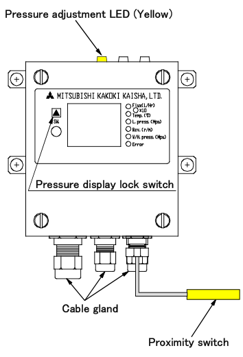
The light-liquid outlet pressure may require adjustment after start-up.
The Mitsubishi manual explains that light-liquid outlet pressure is adjusted through the back-pressure control valve to the level required by the monitoring system.
Why outlet pressure matters
Outlet pressure affects:
- Liquid balance
- Interface position
- Leakage monitoring
- Clean-oil discharge
- Hydraulic stability
Adjust only within the manufacturer’s specified range.
Do not use outlet pressure to hide:
- Wrong gravity disc
- Poor water seal
- Blocked outlet
- Incorrect temperature
- Excessive feed rate
15. Stable-running checks after start-up
Once feed is established, monitor:
Mechanical
- Vibration
- Sound
- Motor current
- Bowl speed
- Bearing temperature
- Oil leakage
Thermal
- Heater inlet temperature
- Heater outlet temperature
- Purifier feed temperature
- Temperature-control stability
Hydraulic
- Feed pressure
- Clean-oil outlet pressure
- Water outlet flow
- Operating-water pressure
- Sealing-water quantity
Separation
- Oil at water outlet
- Water in clean oil
- Solids in clean oil
- Sludge discharge behaviour
- Interface stability
Control
- Alarm state
- Leakage monitor
- Automatic discharge timer
- Valve positions
- Feed-valve status
16. Normal start-up current and vibration
Current
Current is often high during acceleration and settles as the bowl reaches speed.
The Mitsubishi instructions give a typical settled current range of about 50–70% of rated current for the referenced equipment.
A high current that does not settle may indicate:
- Mechanical friction
- Bearing problem
- Drive problem
- Incorrect bowl assembly
- Motor fault
- Low voltage
Vibration
Temporary vibration may occur while passing through a critical speed.
Persistent or large vibration at rated speed is abnormal.
Possible causes:
- Unbalanced sludge
- Incorrect disc assembly
- Damaged bowl part
- Bearing damage
- Spindle problem
- Bowl rubbing
- Loose foundation
If abnormal vibration remains at rated speed, stop and investigate.
17. Start-up flow diagram
18. Type-specific start-up differences
Different purifier configurations may use different automatic sequences.
Examples include:
- Total-discharge type
- Partial-discharge type
- Fuel-oil purifier
- Lubricating-oil purifier
- Clarifier arrangement
- Automatic-control configuration
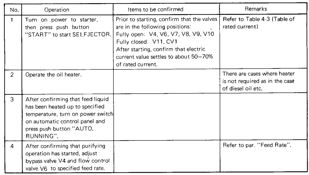
The Mitsubishi manual gives separate start-up tables for different types. One total-discharge procedure includes starting the starter, confirming heated feed liquid, powering the automatic control panel, and using the automatic sequence.
An E-HIDENS arrangement includes heating, starter operation, automatic-control power, automatic running, flow adjustment, temperature stabilisation, and back-pressure adjustment.
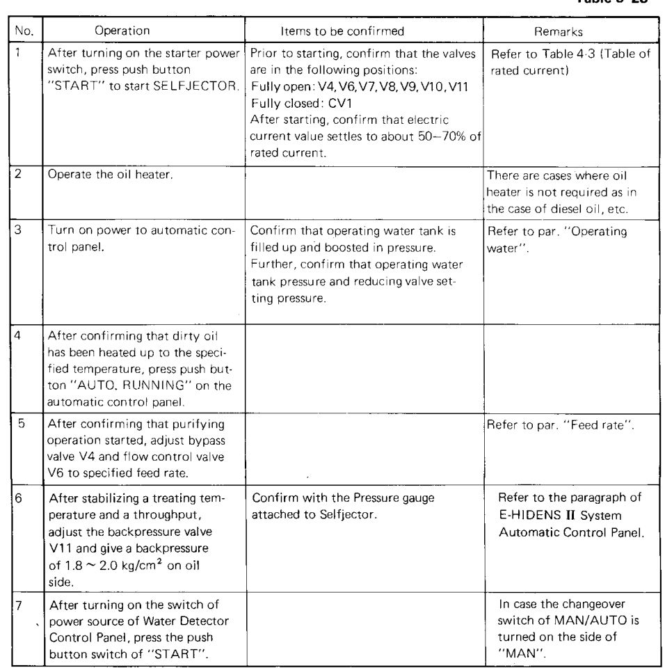
Never combine valve positions from one configuration with the sequence of another.
19. Start-up faults
Fault: purifier does not reach rated speed
Check:
- Motor and electrical supply
- Friction clutch
- Gear case
- Bearings
- Bowl rubbing
- Excessive oil or water resistance
- Incorrect assembly
Do not feed oil until the speed fault is corrected.
Fault: abnormal noise
Immediately stop and investigate:
- Friction clutch
- Gear case
- Bearings
- Bowl contact
- Loose parts
- Foreign objects
Fault: abnormal vibration
If vibration persists after the critical-speed period:
- Stop the purifier.
- Check bowl balance.
- Check disc count and compression.
- Check sludge accumulation.
- Check spindle and bearings.
Fault: heater does not reach temperature
Check:
- Heater supply
- Steam or electrical system
- Temperature-control valve
- Circulation
- Oil viscosity
- Temperature sensor
Fault: oil flows to water outlet during start
Check:
- Water seal
- Bowl closure
- Gravity disc
- Oil temperature
- Feed sequence
- Heavy-liquid outlet
Fault: water appears in clean oil during start
Check:
- Excessive sealing or replacement water
- Interface position
- Gravity disc
- Water outlet
- Feed rate
- Outlet pressure
20. When to stop immediately
Stop the purifier and discontinue feed if there is:
- Persistent abnormal noise
- Large vibration at rated speed
- Contact sound
- Failure to reach rated speed
- Severe oil or water leakage
- Uncontrolled overflow
- Motor current that remains abnormally high
- Sudden loss of outlet pressure
- Dangerous temperature rise
- Failure of the automatic sequence
The Mitsubishi manual specifically instructs immediate stopping when abnormal sound or large vibration is present.
Never open the frame cover until the bowl has completely stopped.
21. Start-up mistakes to avoid
Mistake 1: Feeding oil before rated speed
This prevents proper centrifugal separation and can cause overflow or carry-over.
Mistake 2: Feeding oil before sealing water
Oil can escape through the heavy-liquid outlet.
Mistake 3: Starting the heater without circulation
The heater may overheat or damage the oil.
Mistake 4: Selecting the gravity disc after starting
The disc must be correct before normal treatment.
Mistake 5: Opening feed fully at once
The interface and outlet conditions can be disturbed.
Mistake 6: Ignoring temporary versus abnormal vibration
Temporary vibration during critical-speed passage may be normal; persistent large vibration at rated speed is not.
Mistake 7: Trusting a timer without observing the machine
Automatic control does not replace operator monitoring.
Mistake 8: Using a sequence from another purifier type
Total-discharge, partial-discharge, fuel-oil, lubricating-oil, and clarifier arrangements may have different sequences.
22. Complete start-up checklist
Before start
- [ ] Bowl assembly checked.
- [ ] Bowl nut and frame cover secured.
- [ ] Correct gravity disc installed.
- [ ] Oil source selected.
- [ ] Heater ready.
- [ ] Operating water available.
- [ ] Sealing water available.
- [ ] Valves set correctly.
- [ ] Sludge outlet safe.
- [ ] Starter and control panel ready.
- [ ] Alarms and emergency stop available.
During acceleration
- [ ] Motor starts correctly.
- [ ] No abnormal sound.
- [ ] Vibration reduces after critical-speed passage.
- [ ] Current begins to settle.
- [ ] No leakage.
At rated speed
- [ ] Rated speed confirmed.
- [ ] Current within maker’s expected range.
- [ ] Bowl sound normal.
- [ ] Vibration normal.
Before feed
- [ ] Oil circulating through heater.
- [ ] Oil at specified temperature.
- [ ] Bowl closed.
- [ ] Sealing-water sequence completed.
- [ ] Automatic sequence ready.
After feed
- [ ] Feed introduced gradually.
- [ ] Feed rate adjusted.
- [ ] Light-liquid pressure adjusted.
- [ ] Water outlet normal.
- [ ] No oil at water outlet.
- [ ] No water in clean oil.
- [ ] Sludge-discharge function confirmed.
23. Revision questions with answers
Question 1
What must be confirmed before starting the motor?
Answer: Bowl assembly, covers, valves, oil, water, heater, control panel, alarms, gravity disc, and outlet paths.
Question 2
Why must the bowl reach rated speed before oil feed?
Answer: Adequate centrifugal force and stable hydraulic conditions are required for safe separation.
Question 3
What is the correct basic order for purifier operation?
Answer: Operating speed, sealing water, then oil feed.
Question 4
Why is the oil heater started before feed?
Answer: To reduce viscosity and bring the feed to the specified treating temperature.
Question 5
What does the closing-water system do?
Answer: It moves the sliding bowl mechanism into the sealed position and closes the discharge path.
Question 6
What does the AUTO START control do?
Answer: It begins the programmed automatic running sequence after the purifier reaches rated speed.
Question 7
What current range is given as a typical settled value in the Mitsubishi start-up instruction?
Answer: Approximately 50–70% of rated current for the referenced equipment, subject to the maker’s table.
Question 8
What vibration may occur normally during starting?
Answer: Temporary vibration while the bowl passes through a critical speed.
Question 9
What vibration is abnormal?
Answer: Large or persistent vibration after rated speed is reached.
Question 10
Why is feed introduced gradually?
Answer: To avoid disturbing the interface, overloading the bowl, and causing outlet carry-over.
Question 11
What should be checked if oil appears at the water outlet during start-up?
Answer: Water seal, bowl closure, gravity disc, oil temperature, feed sequence, and heavy-liquid outlet.
Question 12
When must the purifier be stopped immediately?
Answer: For abnormal sound, large vibration, failure to reach speed, severe leakage, high current, dangerous heating, or control-sequence failure.
24. Self-test sequence exercise
Put these actions in the correct order:
- Start oil feed
- Confirm rated speed
- Supply sealing water
- Inspect valves and bowl
- Start heater and circulate oil
- Start the motor
- Adjust feed rate
- Confirm bowl closure
- Confirm oil temperature
- Monitor outlets
Correct order: